Transcription
www.keithley.com2260B SeriesMulti-Range Programmable DC Power SuppliesU ser Manual077-1046-01/ August 2015A Greater Measure of ConfidenceA Tektronix Company
ADDENDUMPlease replace the “Set up” section on page 40 through page 41 ofthe 2260B user manual with the following replacement:Set UpLine Voltage Connection – 1080W ModelsBackgroundWarningThe 1080W (2260B-30-108/80-40/ 250-13/8004) models use a universal power input that canbe used with 100 and 200 VAC systems. Toconnect or replace the power cord, use theprocedure below:The following procedure should only be attemptedby competent persons.Ensure the AC power cord is not connected topower.Removal1. Turn off the power switch.12. Unscrew the power cordstrain relief.3. Remove the 2 screwsholding the power cordcover and remove.32
4. Slide the cover off the ACterminals.45. Remove the AC powercord wires.1. Thread the power cord through the strain reliefand through the power cord cover. White/Blue /Black(India) Neutral (N)Green/Green-yellow GND ( )Black/Brown/Red(India) Line (L)3. Set the cover over the ACterminals.3NLLine2. Connect the AC power cordwires to the AC inputterminals.Neutral1GroundInstallation5
4. Screw the power cord coveronto the rear panel usingthe supplied screws.5. Screw the strain relief ontothe power cord cover.45
Series 2260BMulti-Range Programmable DC Power SuppliesUSER MANUALISO-9001 CERTIFIED MANUFACTURER
This manual contains proprietary information, which is protected bycopyright. All rights are reserved. No part of this manual may bephotocopied, reproduced or translated to another language withoutprior written consent.The information in this manual was correct at the time of printing.However, we continue to improve products and reserves the rights tochange specification, equipment, and maintenance procedures at anytime without notice.
Table of ContentsTable of ContentsSAFETY INSTRUCTIONS . 5GETTING STARTED . 92260B Series Overview . 11Appearance . 18Theory of Operation . 25OPERATION . 38Set Up . 40Basic Operation . 60Parallel / Series Operation . 75Test Sequence . 90CONFIGURATION . 102Configuration . 103ANALOG CONTROL . 122Analog Remote Control Overview. 123Remote Monitoring . 139COMMUNICATION INTERFACE . 144Interface Configuration . 145FIRMWARE UPGRADE PROCEDURE . 158Firmware Update . 159Check the Firmware Version . 162Kernel Update . 164Check the Kernel Version . 167MAINTENANCE . 1693
2260B Series User ManualFAQ . 171APPENDIX . 1732260B Default Settings . 173Error Messages & Messages . 176LED Display Format . 1762260B Specifications . 1772260B Dimensions . 194INDEX . 2014
SAFETY INSTRUCTIONSSAFETY INSTRUCTIONSThis chapter contains important safetyinstructions that you must follow duringoperation and storage. Read the following beforeany operation to insure your safety and to keepthe instrument in the best possible condition.Safety SymbolsThese safety symbols may appear in this manual or on theinstrument.WARNINGWarning: Identifies conditions or practices thatcould result in injury or loss of life.CAUTIONCaution: Identifies conditions or practices thatcould result in damage to the instrument or toother properties.DANGER High VoltageAttention Refer to the ManualProtective Conductor TerminalEarth (ground) Terminal5
2260B Series User ManualDo not dispose electronic equipment as unsortedmunicipal waste. Please use a separate collectionfacility or contact the supplier from which thisinstrument was purchased.Safety GuidelinesGeneralGuidelineCAUTION Do not place any heavy object on theinstrument. Avoid severe impact or rough handling thatleads to damaging the instrument. Do not discharge static electricity to theinstrument. Use only mating connectors, not bare wires, forthe terminals. Do not block the cooling fan opening. Do not disassemble the instrument unless youare qualified.(Measurement categories) EN 61010-1:2010 and EN 61010-2-030specify the measurement categories and their requirements asfollows. The 2260B falls under category II. Measurement category IV is for measurement performed at thesource of low-voltage installation. Measurement category III is for measurement performed in thebuilding installation. Measurement category II is for measurement performed on thecircuits directly connected to the low voltage installation. 0 is for measurements performed on circuits not directlyconnected to Mains.Power SupplyWARNING6 To avoid electrical shock connect the protectivegrounding conductor of the AC power cord toan earth ground.
SAFETY INSTRUCTIONSCleaning theInstrumentOperationEnvironment Disconnect the power cord before cleaning. Use a soft cloth dampened in a solution of milddetergent and water. Do not spray any liquid. Do not use chemicals containing harsh materialsuch as benzene, toluene, xylene, and acetone. Location: Indoor, no direct sunlight, dust free,almost non-conductive pollution (Note below) Relative Humidity: 20% 85% Altitude: 2000m Temperature: 0 C to 50 C(Pollution Degree) EN 61010-1:2010 and EN 61010-2-030specify thepollution degrees and their requirements as follows. The Instrumentfalls under degree 2.Pollution refers to “addition of foreign matter, solid, liquid, orgaseous (ionized gases), that may produce a reduction of dielectricstrength or surface resistivity”. Pollution degree 1: No pollution or only dry, non-conductivepollution occurs. The pollution has no influence. Pollution degree 2: Normally only non-conductive pollutionoccurs. Occasionally, however, a temporary conductivity causedby condensation must be expected. Pollution degree 3: Conductive pollution occurs, or dry, nonconductive pollution occurs which becomes conductive due tocondensation which is expected. In such conditions, equipmentis normally protected against exposure to direct sunlight,precipitation, and full wind pressure, but neither temperaturenor humidity is controlled.StorageenvironmentDisposal Location: Indoor Temperature: -25 C to 70 C Relative Humidity: 90%Do not dispose this instrument as unsortedmunicipal waste. Please use a separate collectionfacility or contact the supplier from which thisinstrument was purchased. Please make surediscarded electrical waste is properly recycled toreduce environmental impact.7
2260B Series User ManualPower cord for the United KingdomWhen using the power supply in the United Kingdom, make surethe power cord meets the following safety instructions.NOTE: This lead/appliance must only be wired by competent personsWARNING: THIS APPLIANCE MUST BE EARTHEDIMPORTANT: The wires in this lead are coloured in accordance with thefollowing code:Green/ Yellow:EarthBlue:NeutralBrown:Live (Phase)As the colours of the wires in main leads may not correspond withthe coloured marking identified in your plug/appliance, proceedas follows:The wire which is coloured Green & Yellow must be connected tothe Earth terminal marked with either the letter E, the earth symbolor coloured Green/Green & Yellow.The wire which is coloured Blue must be connected to the terminalwhich is marked with the letter N or coloured Blue or Black.The wire which is coloured Brown must be connected to theterminal marked with the letter L or P or coloured Brown or Red.If in doubt, consult the instructions provided with the equipmentor contact the supplier.This cable/appliance should be protected by a suitably rated andapproved HBC mains fuse: refer to the rating information on theequipment and/or user instructions for details. As a guide, a cableof 0.75mm2 should be protected by a 3A or 5A fuse. Largerconductors would normally require 13A types, depending on theconnection method used.Any exposed wiring from a cable, plug or connection that isengaged in a live socket is extremely hazardous. If a cable or plug isdeemed hazardous, turn off the mains power and remove the cable,any fuses and fuse assemblies. All hazardous wiring must beimmediately destroyed and replaced in accordance to the abovestandard.8
GETTING STARTEDGETTING STARTEDThis chapter describes the power supply in anutshell, including its main features and front /rear panel introduction. After going through theoverview, please read the theory of operation tobecome familiar with the operating modes,protection modes and other safety considerations.2260B Series Overview . 11Series lineup .11Main Features .12Accessories .132260B-30/80 Accessories .132260B-250/800 Accessories .15Package Contents.17Appearance . 182260B Front Panel .18Rear Panel .21Theory of Operation . 25Operating Area Description .25CC and CV Mode .28Slew Rate .30Bleeder Control .30Internal Resistance.31Alarms .329
2260B Series User ManualConsiderations . 33Grounding . 3610
GETTING STARTED2260B Series OverviewSeries lineupThe 2260B series consists of 12 models, divided into 3 differentmodel types covering 3 power capacities: 360W models, 720Wmodels and 1080W models.Throughout the user manual, 2260B-30, 2260B-80,2260B-250 or 2260B-800 will refer to any of the2260B models with a maximum voltage rating of30V, 80V, 250V or 800V, respectively.NoteModel nameTypeVoltage Rating Current RatingPower2260B-30-36360W models0 30V0 36A360W2260B-80-13360W models0 80V0 13.5A360W2260B-250-4360W models0 250V0 4.5A360W2260B-800-1360W models0 800V0 1.44A360W2260B-30-72720W models0 30V0 72A720W2260B-80-27720W models0 80V0 27A720W2260B-250-9720W models0 250V0 9A720W2260B-800-2720W models0 800V0 2.88A720W2260B-30-108 1080W models 0 30V0 108A1080W2260B-80-400 40.5A1080W2260B-250-13 1080W models 0 250V0 13.5A1080W2260B-800-40 4.32A1080W1080W models 0 80V1080W models 0 800V11
2260B Series User ManualApart from the differences in output, each unit differs in size. The720W and 1080W models are larger than the 360W models toaccommodate the increase in power.360 W models720 W models1080 W modelsMain FeaturesPerformanceFeatures12 High performance/power Power efficient switching type power supply Low impact on load devices Fast transient recovery time of 1ms Fast output response time OVP, OCP and OTP protection Adjustable voltage and current slew rates User adjustable bleeder control to quicklydissipate the power after shutdown to safelevels. Extensive remote monitoring and controloptions Support for series* and parallel connections.*(30, 80 volt models only) Power on configuration settings. Web server monitoring and control
GETTING STARTEDInterface Ethernet port Analog connector for analog voltage and currentmonitoring USB host and device portAccessoriesPlease check the contents before using the 2260B.2260B-30/80 AccessoriesStandard Part numberAccessoriesDescription196353000Test Leads x1(10AWG, Max. 45A,Max.600V)174627900USB Cable020312300Basic Accessories Kit:(360W, 720W)M4 terminal screws and washers x2, M8terminal bolts, nuts and washers x2, Airfilter x1, Analog control protectiondummy x1, Analog control lock lever x1,Output terminal cover (top & bottom)060316400Basic Accessories Kit:(1080W)M4 terminal screws and washers x2, M8terminal bolts, nuts and washers x2, Airfilter x1, Analog control protectiondummy x1, Analog control lock lever x1,Output terminal cover (top & bottom),Strain relief.063453401CD-R 2260B Manuals & Drivers071305502Quick Start GuidePWRKI A*Power cord071305700China RoHS Declaration001163200Calibration of Traceable Certificate13
2260B Series User Manual001163300OptionalPart numberAccessories2260-001Packing Check ListDescriptionAccessory Kit:Pin contact x10, Socket x1, Protectioncover x12260-002Simple IDC Tool2260-003Contact Removal Tool2260-004Basic Accessory Kit:M4 terminal screws and washers x2, M8terminal bolts, nuts and washers x2, Airfilter x1, Analog control protectiondummy x1, Analog control lock lever x1,Output terminal cover (top & bottom),Strain relief2260-005Cable for 2 units in Series connection.2260-006Cable for 2 units in Parallel connection.2260-007Cable for 3 units in Parallel connection.2260-008Test Lead Set with Lugs2260B-EXTERMExtended terminal2260B-RMK-JISRack mount adapter (JIS)2260B-RMK-EIARack mount adapter (EIA)2260B-GPIB-USB GPIB to USB adapterDownload NameDescriptionkeithley 2260B.inf USB driver14
GETTING STARTED2260B-250/800 AccessoriesStandard Part numberAccessoriesDescription196353900Test Leads x1(20AWG, Max. 9A, Max.3kV)174627900USB Cable020315700Basic Accessories Kit: (360W, 720W)Air filter x1, Analog control protectiondummy x1, Analog control lock lever x1,Output terminal cover (top & bottom),High voltage output terminal060316500Basic Accessories Kit: (1080W)Air filter x1, Analog control protectiondummy x1, Analog control lock lever x1,Output terminal cover (top & bottom),High voltage output terminal, Strain relief063453401CD-R 2260B Manuals & Drivers071305502Quick Start GuidePWRKI A*Power cord071305700China RoHS Declaration001163200Calibration of Traceable Certificate001163300Packing Check List15
2260B Series User ManualOptionalPart numberAccessories2260-001DescriptionAccessory Kit:Pin contact x10, Socket x1, Protectioncover x12260-002Simple IDC Tool2260-003Contact Removal Tool2260-005Cable for 2 units in Series connection.2260-006Parallel operation cable for 2 units.2260-007Parallel operation cable for 3 units.2260-009Test Leads (for High Voltage)2260-010Basic Accessories Kit:Air filter x1, Analog control protectiondummy x1, Analog control lock lever x1,Output terminal cover (top & bottom),High voltage output terminal, Strain relief2260B-EXTERMHVExtended terminal (For 250V/800V HVmodels)2260B-RMK-JISRack mount adapter (JIS)2260B-RMK-EIARack mount adapter (EIA)2260B-GPIB-USB GPIB to USB adapterDownload NameDescriptionkeithley 2260B.inf USB driver16
GETTING STARTEDPackage ContentsCheck the contents before using the 2260B.Opening the boxContents(single unit) Main unit Power cord x1 Test leads x1 USB cableChina RoHSDeclaration Basic Accessories Kit CD-R ManualCalibration ofTraceable Certificate Quick Start Guide Packing Check List17
2260B Series User ManualAppearance2260B Front Panel2260B-30-72, 80-27, 250-9, 800-2 tkeyPowerswitchFunctionkeysUSB Aport2260B-30-108, 80-40, 250-13, 800-4 (1080W)2260B-30-108 1080W182260B-30-36, 80-13,250-4, 800-1 (360W)
GETTING STARTEDFunction KeysThe Function keys along with the Output key willlight up when a key is active.The Function key is used toconfigure the power supply.Set the overcurrent or overvoltageprotection levels.Sets the current and voltage limits.Used to run customized Testsequence for testing.Locks or unlocks the panel keys toprevent accidentally changingpanel settings.Toggles the display from viewingV/A V/W or A/W*.*Press the Voltage knob for V/W,press the Current knob for 0%WVoltage Slew RateConstant Voltage ModeRemote Control ModeAlarm onDelay OutputConstant Current ModeCurrent Slew RatePower barIndicates the current power outputas a percentage.19
2260B Series User ManualVoltage KnobSets the voltage.Current KnobSets the current.OutputPress to turn on the output. TheOutput key will light up when theoutput is active.USBThe USB A port is used to updatethe firmware. The firmware canonly be updated at a servicecenter.Power SwitchUsed to turn the power on/off.20
GETTING STARTEDRear Panel2260B-30-72, 80-27 (720W)Sense terminalAnalog controlconnectorUSB BportOutputterminal( )ChassisgroundSenseterminalSER.NO. LABELOutputterminal (-)FanLANLANAC10047 63Hz240V1000VA MAX.AC Input2260B-30-36, 80-13(360W)2260B-30-108, 80-40 (1080W)AC InputSER.NO. LABELLANNAC 10047 63HzLAC 10047 63Hz240V500VA MAX.240V1500VA MAX.LAN21
2260B Series User Manual2260B-250-9, 800-2 (720W)Sense terminalAnalog controlconnectorUSB BportOutputterminals VSenseterminalVSN.C. SVSER.NO. LABELChassisgroundOutputterminals -VFanLANLANAC 100 240V47 63Hz 1000VA MAX.AC Input2260B-250-4, 800-1(360W)2260B-250-13, 800-4 (1080W)AC InputVSN.C. SLANVSER.NO. LABELNVSN.C. SVAC 100 240V47 63Hz 500VA MAX.LAC 100 240V47 63Hz 1500VA MAX.LAN22
GETTING STARTEDStandard 26 pin MIL connector(OMRON XG4 IDC plug).Analog ControlConnectorThe analog control connector isused to monitor current and voltageoutput, machine status (OVP, OCP,OTP etc.), and for analog control ofthe current and voltage output.Use an OMRON XG5 IDC socket asthe mating socket.Positive ( ) and negative (-) outputterminals.Output Terminals(30, 80 voltmodels)Chassis groundSense (-S) and Sense ( S) terminals.Output Terminals The 250 and 800 volt models use a 9 pin connector(250, 800 voltand a plug for the output and sense terminalmodels)connections. The plug is a MC420-38109Z plug byDECA SwitchLab Inc. This plug is also availableseparately.VSN.C. SVVSN.C. SSN.C. SPositive (V ) and negative (V-)output terminals (3 of each).VVVChassis groundSense (-S) and Sense ( S)terminals.23
2260B Series User ManualUSB B portThe USB B port is used for remotecontrol.FansTemperature controlled fansEthernet PortThe Ethernet port is used for remotecontrol and digital monitoring froma PC.LAN360W models:2260B-30-36/80-13/250-4/ 800-1Line VoltageInput720W models:2260B-30-72/80-27/250-9/ 800-2 Voltage Input: 100 240 VAC Line frequency: 50Hz/60 Hz(Automatically switchable) AC Input voltage range:85VAC 265VAC Frequency: 47Hz 63HzLine VoltageInput24NL1080W models:2260B-30-108/80-40/250-13/800-4 Voltage Input: 100 240 VAC Line frequency: 50Hz/60 Hz(Automatically switchable)
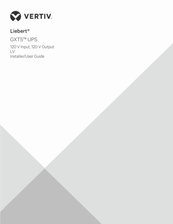
GETTING STARTEDTheory of OperationThe theory of operation chapter describes the basic principles ofoperation, protection modes and important considerations thatmust be taken into account before use.Operating Area DescriptionBackgroundThe 2260B power supplies are regulated DCpower supplies with a high voltage and currentoutput. These operate in CC (Constant current)or CV (Constant voltage) mode within a wideoperating range limited only by the outputpower.The operating area of each power supply isdetermined by the rated output power as wellas the voltage and current rating. For examplethe operating area and rated power output forthe 2260B- 30-36 is shown below.Voltage30Operating Area360W rated power101236CurrentWhen the power supply is configured so thatthe total output (current x voltage output) isless than the rated power output, the powersupply functions as a typical constant current,constant voltage power supply.If however, the power supply is configuredsuch that the total output (current x voltage25
2260B Series User Manualoutput) exceeds the rated power output, theeffective output is actually limited to the powerlimit of the unit. In this case the output currentand voltage then depend purely on the loadvalue.Below is a comparison of the operating areas ofeach power supply.2260B 800V Series Operating AreaVoltage (V)0.45 0.9 1.35 W1080W250021345Current (A)2260B 250V Series Operating Area1.44 2.88 4.32 4.5913.5Voltage (V)250250360W720W1080W20015010080500036Current (A)2691215
GETTING STARTED2260B 80V Series Operating Area4.59.02713.540.5Voltage 5Current (A)2260B 30V Series Operating AreaVoltage 6080100120Current (A)27
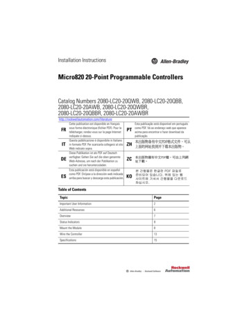
2260B Series User ManualCC and CV ModeCC and CV modeDescriptionWhen the power supply is operating inconstant current mode (CC) a constant currentwill be supplied to the load. When in constantcurrent mode the voltage output can vary,while the current remains constant. When theload resistance increases to the point where thecurrent limit (ISET) can no longer be sustainedthe power supply switches to CV mode. Thepoint where the power supply switches modesis the crossover point.When the power supply is operating in CVmode, a constant voltage will be supplied tothe load, while the current will vary as the loadvaries. At the point that the load resistance istoo low to maintain a constant voltage, thepower supply will switch to CC mode andmaintain the set current limit.The conditions that determine whether thepower supply operates in CC or CV modedepends on the set current (ISET), the set voltage(VSET), the load resistance (RL) and the criticalresistance (RC). The critical resistance isdetermined by VSET/ISET. The power supplywill operate in CV mode when the loadresistance is greater than the critical resistance.This means that the voltage output will beequal to the VSET voltage but the current will beless than ISET. If the load resistance is reducedto the point that the current output reaches theISET level, the power supply switches to CCmode.28
GETTING STARTEDConversely the power supply will operate inCC mode when the load resistance is less thanthe critical resistance. In CC mode the currentoutput is equal to ISET and the voltage output isless than VSET.VRL RCCVVSETCrossoverpointRL RCCCRL RCISETI29
2260B Series User ManualSlew RateTheoryThe 2260B has selectable slew rates for CC andCV mode. This gives the 2260B power supplythe ability to limit the current/voltage draw ofthe power supply. Slew rate settings aredivided into High Speed Priority and SlewRate Priority. High Speed Priority modedisables slew rate settings for CC or CV mode.Slew Rate Priority mode allows for useradjustable slew rates for CC or CV mode. Therising and falling slew rate can be setindependently.Slew rate DisabledSlew rate EnabledBleeder ControlBackgroundThe 2260B DC power supplies employ a bleedresistor in parallel with the output terminals.2260BBleedresistorLoadBleed resistors are designed to dissipate thepower from the power supply filter capacitors30
GETTING STARTEDwhen power is turned off and the load isdisconnected. Without a bleed resistor, powermay remain charged on the filter capacitors forsome time and be potentially hazardous.In addition, bleed resistors also allow forsmoother voltage regulation of the powersupply as the bleed resistor acts as a minimumvoltage load.The bleed resistance can be turned on or offusing the configuration settings.NoteBy default the bleed resistance is on. For batterycharging applications, be sure to turn the bleedresistance off as the bleed resistor can dischargethe connected battery when the unit is off.Internal ResistanceBackgroundOn the 2260B, the internal resistance of thepower supply can be user-defined in software.(Internal Resistance Setting, page 31). When theinternal resistance is set it can be seen as aresistance in series with the positive outputterminal. This allows the power supply tosimulate power sources that have internalresistances such as lead acid batteries.InternalResistance RangeUnit 250-13Internal Resistance Range0.000 0.833Ω0.000 0.417Ω0.000 0.278Ω0.000 5.926Ω0.000 2.963Ω0.000 1.975Ω0.00 55.55Ω0.00 27.77Ω0.00 18.51Ω31
2260B Series User Manual2260B-800-12260B-800-22260B-800-40.0 555.5Ω0.0 277.8Ω0.0 185.1ΩAlarmsThe 2260B power supplies have a number of protection features.When one of the protection alarms are set, the ALM icon on thedisplay will be lit. For details on how to set the protection modes,please see page 60.OVPOvervoltage protection (OVP) prevents a highvoltage from damaging the load.OCPOvercurrent protection prevents high currentfrom damaging the load.OTPOvertemperature protection protects theinstrument from overheating.Power Switch TripWhen the Power Switch Trip configurationsetting is enabled, the power supply willautomatically shut down when a protectionsetting has been tripped (OCP, OVP, OTP).Alarm outputAlarms are output via the analog controlconnector. The alarm output is an isolatedopen-collector photo coupler output.32
GETTING STARTEDConsiderationsThe following situations should be taken into consideration whenusing the power supply.Inrush currentCautionPulsed or PeakedloadsWhen the power supply switch is first turnedon, an inrush current is generated. Ensure thereis enough power available for the powersupply when first turned on, especially if anumber of units are turned on at the sametime.Allow at least 15 seconds between cycling thepower. Cycling the power on and off quickly cancause the inrush current limiting circuit to fail aswell as reduce the working life of the input fuseand power switch.When the load has current peaks or is pulsed, itis possible for the maximum current to exceedthe mean current value. The 2260B powersupply ammeter only indicates mean currentvalues, which means for pulsed current loads,the actual current can exceed the indicatedvalue. For pulsed loads, the current limit mustbe increased, or a power supply with a greatercapacity must be chosen. As shown below, apulsed load may exceed the current limit andthe indicated current on the power supplyammeter.33
2260B Series User ManualCurrent limitlevelMeasuredAmmetercurrentReverse Current:Regenerative loadWhen the power supply is connected to aregenerative load such as a transformer orinverter, reverse current will feed back to thepower supply. The 2260B power supply cannotabsorb reverse current. For loads that createreverse current, connect a resistor in parallel tothe power supply to bypass the reversecurrent. This description only applies when thebleed resistance is off.2260BResistorLoadReverse currentNoteThe current output will decrease by the amount ofcurrent absorbed by the resistor.Ensure the resistor used can withstand the powercapacity of the power supply/load.34
GETTING STARTEDReverse Current:Accumulativeenergy.When the power supply is connected to a loadsuch as a battery, reverse current may flowback to the power supply. To prevent damageto the power supply, use a reverse-currentprotection diode in series between the powersupply and load.Diode2260BCAUTIONLoadEnsure the reverse withstand voltage of the diodeis able to withstand 2 times the rated outputvoltage of the power supply and the forwardcurrent capacity can withstand 3 to 10 times therated output current of the power supply.Ensure the diode is able to withstand the heatgenerated in the following scenarios.When the diode is used to limit reverse voltage,remote sensing cannot be used.35
2260B Series User ManualGroundingThe output terminals of the 2260B power supplies are isolated withrespect to the protective grounding terminal. The insulationcapacity of the load, the load cables and other connected devicesmust be taken into consideration when connected to the protectiveground or when floating.FloatingAs the output terminals are floating, the loadand all load cables must have an insulationcapacity that is greater than the isolationvoltage of the power d) Insulation capacity isolation voltageof power supplyIf the insulation capacity of the load and loadcables is not greater than the isolation voltage ofthe power supply, electric shock may occur.
GETTING STARTEDGrounded outputterminalIf the positive or negative terminal is connectedto the prot
Location: Indoor, no direct sunlight, dust free, almost non-conductive pollution (Note below) Relative Humidity: 20% 85% Altitude: 2000m Temperature: 0 C to 50 C (Pollution Degree) EN 61010-1:2010 and EN 61010-2-030specify the pollution degrees and their requirements as follows. The Instrument falls under degree 2.