Transcription
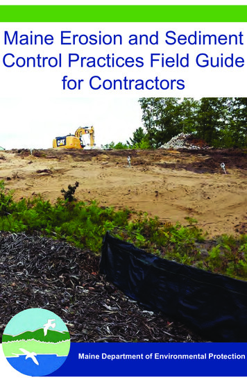
Maine Erosion and SedimentControl Practices Field Guidefor ContractorsMaine Department of Environmental Protection
ACKNOWLEDGEMENTSProduction2014 Revision: Marianne Hubert, Senior Environmental Engineer,Division of Watershed Management, Bureau of Land and WaterQuality, Department of Environmental Protection (DEP).Illustrations: Photos obtained from SJR Engineering Inc., ShawBrothers Construction Inc., Bar Mills Ecological, Maine Departmentof Transportation (MaineDOT), Maine Land Use PlanningCommission (LUPC) and Maine Department of EnvironmentalProtection (DEP).TECHNICAL REVIEW COMMITTEE: The following peopleparticipated in the revision of this manual:Steve Roberge, SJR Engineering, Inc., AugustaRoss Cudlitz, Engineering Assistance & Design, Inc., YarmouthSusan Shaller, Bar Mills Ecological, BuxtonDavid Roque, Department of Agriculture, Conservation & ForestryPeter Newkirk, MaineDOTBob Berry, Main-Land Development ConsultantsDaniel Shaw, Shaw Brothers ConstructionPeter Hanrahan, E.J. PrescottWilliam Noble, William Laflamme, David Waddell, Kenneth Libbey,Ben Viola, Jared Woolston, and Marianne Hubert of the Maine DEPRevision (2003): The manual was revised and reorganized withillustrations (original manual, Salix, Applied Earthcare and RossCudlitz, Engineering Assistance & Design, Inc.).Original Manual (1991): The original document was funded froma US Environmental Protection Agency Federal Clean Water Actgrant to the Maine Department of Environmental Protection, NonPoint Source Pollution Program and developed under contract bythe Cumberland County Soil and Water Conservation District.
Table of ContentsIntroduction iThe Erosion and Sediment Control Plan iiiA - SITE DEVELOPMENT 1CONSTRUCTION ENTRANCE / EXIT 2DUST CONTROL 4OVERWINTER CONSTRUCTION 5WATER DIVERSION8 EXCAVATION DEWATERING 11CONCRETE WASHOUTS 13STOCKPILES 14B - SEDIMENT CONTROLS SILT FENCE 1517EROSION CONTROL MIX BERM 19FILTER SOCKS 20STONE CHECK DAMS 22STORMDRAIN INLET PROTECTION 24HAY BALES 26C – SEDIMENT CONTAINMENT 27SEDIMENT TRAPS 28SEDIMENT BASINS 29
GEOTEXTILE FILTER BAG 32FLOCCULANTS (POLYMERS) 34D - MULCHING 35HAY/STRAW MULCH 37EROSION CONTROL BLANKETS 39EROSION CONTROL MIX 41HYDRAULIC MULCH 43E - VEGETATION 44TOPSOIL 46SEEDBED PREPARATION 47VEGETATION APPLICATION 48SODDING 50HYDROSEEDING 50F - SLOPES 51CUTS AND FILLS 53GEOTEXTILES 55RIPRAP 56GABIONS 61TURF-REINFORCED MATTING (TRM) 63CELLULAR CONFINEMENT SYSTEMS 64SLOPE DRAINS 65
G - SWALES AND DITCHES 67VEGETATED CHANNELS69 RIPRAP CHANNEL TURF REINFORCEMENT MAT72 LEVEL SPREADERS H - CROSS-CULVERTS 747578PIPE INLET PROTECTION 81OUTLET PROTECTION 82I - ROADS 85GRAVEL ROADS 86DITCH TURNOUTS 89FRENCH DRAINS AND ROCK SANDWICHES 92J - STREAM CROSSINGS 94CULVERT CROSSINGS 95TEMPORARY STREAM DIVERSION 99IN-WATER WORK 101TEMPORARY STREAM CROSSINGS 103APPENDIX A: Erosion and Sediment ControlLaws in Maine 106APPENDIX B: MaineDOT StandardSpecifications 109
IntroductionContaminants, sediments or nutrients such as phosphorus,attach to the soil particles and contribute to “non-pointsource pollution”. The environmental impact of erosionand sedimentation can be irreparable; and planning forand preventing the erosion in the first place can be lesscostly than labor intensive repairs later. The purpose ofthis handbook is to help land developers, consultants, andcontractors use the appropriate erosion and sedimentationcontrol Best Management Practices (BMPs) for the site andconditions whenever disturbing soil or removing a naturalground cover.Large-scale development areas exposed to erosion duringconstruction have the greatest potential for significantsedimentation of a resource. But, a small discharge of turbidwater from a simple residential lot development can alsohave damaging effects.WHAT ARE EROSION AND SEDIMENTATION?Soil erosion is the detachment of soil particles and lossof surficial soil by the actions of water, ice, gravity, orwind. Water-generated erosion causes the most severedamage to a site under development. Sedimentation is theconsequence of erosion when the eroded soil particles aredeposited in a new location.HOW DOES EROSION OCCUR?Because the rate of erosion compounds exponentially, it isvital to control its initial stages. Raindrop erosion occurs when raindrops falls anddislodges individual soil particles from an unprotectedsoil surface. These particles are easily picked up andtransported great distances by stormwater runoff.i
Sheet erosion occurs when the runoff removes awhole layer of an unprotected soil surface. Rill and gully erosion occurs as the runoffconcentrates in rivulets and cuts into the soil surface.When not repaired, the rills develop into larger gullies. Stream and channel erosion occurs as theincreased volume and velocity of the runoff reaches astream or waterway and cuts away at the banks of thechannel.OTHER FACTORS LINKED TO EROSIONErosion potential is directly related to the soil’s capacity tohold and transfer water such as: Soils with good structure are less prone to erosion;but soil compaction like soil disturbance may destroythe soil structure, and increase erosion and runoffpotential. A soil with high amounts of silt or veryfine sand is more erodible than a soil with a higherpercentage of clay or organic matter. Well-drainedand well-graded gravels with little or no silt are theleast erodible soils. A ground surface that is well vegetated is shieldedfrom the impact of falling rain and will resist thevelocity of runoff. Also, the root systems hold the soilparticles and aid in absorbing water. Pavement or agravel base is also considered a proper cover. A slope length and gradient will determine the velocityof the runoff and the extent of erosion. Steep and/orlong slopes are the most subject to erosion. The intensity and duration of a rainfall eventdetermines the volume and velocity of runoff andtherefore its energy. Long duration rainfall eventscause the most severe erosion.ii
The Erosion and Sediment ControlPlanAll projects permitted through the DEP need an erosion andsediment control (ESC) plan; but proper planning is alsoimportant for all other projects, and especially if located in anarea at risk of eroding and causing sedimentation. The ESCplan should be prepared during the design phase and beforeconstruction begins; and the contractor should understandthe plan, implement it in a timely manner, and adjust themeasures as site or weather conditions change. The ESCplan only establishes the minimum required measures. Theplan consists of three parts:1. A description: Existing conditions and the proposed activities, siteconditions (soils, topography, vegetation, propertylines, buildings, etc.), and adjacent protected naturalresources (streams, wetlands, slopes, bare or highlyerodible soils, significant wildlife habitats, etc.). Areas that are subject to serious erosion problems. Measures that will be used to control erosion andsedimentation, where they will be installed and whenneeded. Construction schedule and planned inspections withfrequency and required maintenance.2. Site Plans Topographic land contours and drainage before andafter construction. The limits of vegetation clearing and grading. Any vegetated buffers that should be protected. Sensitive areas within 100 feet of the site (streams,lakes, wetlands or areas sensitive to erosion.iii
Drainage swales, ditches, roads, and stormwatercontrol structures. The location and types of ESC measures.3. Construction Details Plans and standards of ESC structures. Amount, type and installation details for seeding,mulching and other vegetative specifications. All pertinent maintenance instructions. Schedule for stabilization and revegetation includingoverwinter stabilization measures if the work extendsinto the winter construction period (see OverwinterConstruction).IMPORTANT NOTE:Consider and plan for unforeseen conditions, weatherand delays that may affect the construction scheduleand BMP performance. Will grading be completedbefore winter? Will all measures be effective duringeach phase of the project?iv
The SIMPLE Erosionand Sediment Control PlanUse this simple ESC plan for small sites (houselots)S Stabilize disturbed soils before moving on!I Install sediment barriers before construction!M Mulch daily!P Protect natural buffers!L Limit the area of soil disturbance!Evaluate and repair all erosion controls andE sediment measures!v
Plan thedevelopmentto fit the siteMinimizethe area ofexposed soilat one timeStabilizecut and fillslopesBe mindfulof sensitivenaturalresourcesAvoid mudand dustin publicroadwaysSMART DEVELOPMENT STRATEGYDO IT RIGHT THE FIRST TIME!Unnecessary Develop the least critical areas ofgrading shouldthe site and protect the sensitivebe avoidedresources. Build a large developmentproject in small phases.Exposed soilsImmediately stabilize theare sources ofroad and roadside ditches.erosionImmediately seed and mulchareas ready for revegetation. Divert clean runoff to a stableDisturbedarea.slopes are Anchor mulch over seededvulnerable toarea, or use structural materialsunchecked(riprap, gabions, revetments orrunoff.retaining walls, etc.) Use precautions when adjacentto a protected natural resourceor on steep and long slopes.Sedimentation Immediately stabilize allof sensitivechannels or constructed slopesresourcesgreater than 8%.should be Use overwinter practices fromavoided.Oct. 15 to April 15. Mulch any soils that will beexposed for longer than 15 days. Install gravel pads at theconstruction site entrance/exit(s).Mud makesroads slipperyand is anuisance whenit is dry (dust). Use water as dust suppression. Sweep public roads.vi
Use specialmeasuresat streamcrossingsSMART DEVELOPMENT STRATEGYDO IT RIGHT THE FIRST TIME! Install culverts quickly and duringlow stream flow (late summer).Construction Minimize soil disturbanceprojects in oradjacent to streams.adjacent to Consult with the Mainestreams canDepartment of Inland Fisheriesharm aquaticand Wildlife (MDIFW) regardinglife.in-stream activities between July14 and Oct. 2. Avoid channelizing rgepointsRunoff shouldnot dischargeoff site or toa protectednaturalresource Install filter barriers around catchbasin inlets and culverts.Inspect ESCmeasuresand adjust,maintain orrepairESC measureshould beinspectedregularly bya designatedandknowledgeableperson Prescribe frequency ofinspections (once a week, beforeand after every res areunnecessarywhen the siteis stable. Protect larger culverts with stonecheck dams and sediment traps. Use temporary sediment basinsduring construction. Inspect regularly and maintain allESC measures. Follow-up with an inspectionreport to owner, design engineer,and town. ESC measures need to beremoved when the site is stable.vii
Considerations of the existing site conditions, andphasing the construction and development will reduce sitevulnerability to uncontrolled erosion and sedimentation. It willsave both time and money!IMPORTANT NOTES:Beware of site development hidden costs! Phasing andinstalling effective passive erosion control measureswill be less costly and simpler to manage than havingto provide structural sedimentation measures inconcentrated flows or for large volume of water.Appropriate ESC protection is necessary for steepslopes, erodible soils or where surface water orgroundwater makes permanent stabilization difficult.Sites in loamy soils are more erodible than sandy orclayey soils.The potential for erosionis related to the typeof soil, the presence ofwater and the slope’slength and steepness.1SiteDevelopmentA - SITE DEVELOPMENT
SiteDevelopmentCONSTRUCTION ENTRANCE / EXITA pad of coarse aggregate at the construction entrance/exitwill reduce the tracking of soil from construction traffic ontoa public street. Sediments from the tire treads are knockedloose by the angular stones and are trapped in the voidsbetween the stones.COMPANION BMPs: Sediment Trapping andSediment BarriersCONSTRUCTION SPECIFICATIONS The entrance/exit pad should have a length of50 feet or more and a 12-foot minimum width(or as appropriate to contain the wheel base ofconstruction vehicles plus 3 feet on either side). The pad should be 6 inches or more thick withangular aggregate (2-3 inch diameter). Appropriatereclaimed concrete material may be used. The aggregate should be placed over a geotextilefilter to prevent the stones from pushing into thenative soil. At the bottom of slopes, a diversion ridge should beprovided to intercept runoff. Berms may be necessary to divert water aroundany exposed soil, and runoff should be directed to asediment trap. The wheels of construction equipment may bewashed prior to exiting the site. Washing should beperformed in an area that drains to a sediment trapor basin.2
3SiteDevelopmentThe pad should be inspectedweekly as well as before andafter a storm. The pad mayhave to be replaced if the voidsbecome filled with sediment.Street sweeping may benecessary.
SiteDevelopmentDUST CONTROLDusty conditions occur when a disturbed site or road surfacehas dried out; and dust from wind erosion becomes anenvironmental or public concern. Note that a gravel surfacewithout fines results in wash-boarding.Stabilize all laydown areasand all unpaved surfaces witha base gravel or coarse gravelas soon as possible. Usetraffic control to restrict speedand route.Water Application withfrequent reapplication duringwarm sunny days will mitigatedust. The distribution of watershould not cause turbid runoff.Sweep and Vacuum pavedroad surface when dry. Sweepfrom the center line to theedge of the travel way. Do notsweep into a waterbody orwetland. The public roadwaymay also require sweeping.Calcium Chlorideapplications are more cost-effective on larger sites (30%calcium chloride is recommended for most gravel surfaces orfollow the supplier’s guidance).Soil Binders may require pre-wetting, a 24-hour curingtime and minimum temperatures for use. Asphalt or oil-basedbinders are not allowed.4
The winter construction period runs from October 15 throughMay 1st. Additional stabilization measures should beprovided by November 1st for winter and spring snowmeltif a construction site is not permanently stabilized withpavement, a gravel road base, 95% mature vegetation cover,erosion control mulch, or riprap.Ideally, permanent seeding should occur 45 days before thefirst killing frost (different dates for different Maine locations);otherwise, overwinter mulching is necessary. See theVegetation section for more information.COMPANION BMPs: Mulching, SedimentTrapping, Vegetation and SlopesOverwinter Construction DifficultiesCannot be established outsideVegetative Ground Coverof growing season.Snow or icing may clogRunoff Diversiondiversion structures.Should be installed beforeSedimentation Basinsthe ground is frozen. Can beoverwhelmed by spring flows.Difficult to install on frozenSilt Fenceground. Often fails duringspring melt.Cannot be anchored on frozenErosion Control Blanketsground.Stabilizers are ineffective inHydroseedingcold temperatures.Cannot be established outsideVegetated Swalesof growing season.Base gravel on driving/parkingImpervious Stabilizationareas. Pavement cannot beinstalled in winter.5SiteDevelopmentOVERWINTER CONSTRUCTION
SiteDevelopmentOverwinter Hay Mulch should be applied at double thenormal rate (150 pounds per 1000 square feet or 3 tons/acre) and should be anchored with netting (peg and twine)or a tackifier to prevent mulch displacement before freezingconditions. No soil should be visible through the mulch. Haymulch cannot be applied over snow.Dormant Seeding and Mulch should be applied at3 times the specified amount after the first killing frost. Alldormant seeding beds should be covered with overwinterhay mulch or an anchored erosion control blanket.Temporary vegetation should be applied by October1st with winter rye at 3 pounds per 1000 square feet, andmulched with anchored hay at 75 pounds per 1000 squarefeet or with erosion control blankets. If the rye fails to grow atleast three inches and have 75% coverage by November 1st,the area should be stabilized for overwinter protection.Erosion control mix is the best overwinter cover, but isnot recommended for slopes steeper than 1:1 or in areaswith flowing water.Erosion Control Blankets should be used on slopeswhere hay would be disturbed by wind or water. The mattingshould be installed, anchored and stapled in accordance withthe manufacturer’s recommendations. Full contact betweenthe blanket and the soil is critical for an effective erosioncontrol cover.Riprap should be properly sized and installed to ensurelong-term stability. In the winter, newly constructed ditchesand channels should be stabilized with riprap. Widening ofthe channel may be required to accommodate the placementof stones. Angular riprap is preferred to round stone(tailings).6
If construction occurs afterNovember 1st, all disturbedareas should be stabilized daily.Stabilization during the winterconstruction period may includemulching, erosion control mix,erosion control blankets, andstone.Daily inspections in the winterare important if the constructionis active. Any erosion ordischarges should be repairedimmediately.7SiteDevelopmentSod may be used for late-season stabilization (after October1st), but it is not recommended for slopes steeper than 3:1or in areas with groundwater seeps. Follow the supplier’sinstructions.
SiteDevelopmentWATER DIVERSIONA water diversion consists of a channel constructed acrossor above a work site to direct runoff away from a disturbedarea to stable discharge point that is unlikely to erode. It caneither be an excavated ditch that intercepts groundwaterand surface water, or a berm that diverts surface runoff.A permit may be required for dewatering a wetland orwaterbody in accordance with Maine Natural ResourceProtection Act (NRPA). For additional information pleasecontact your nearest DEP regional office.COMPANION BMPs: Riprap, Mulching, SedimentTrapping and VegetationA temporary diversion structureis most important during astorm event until the area isrevegetated and stable.The water diversion shouldalways be kept clear ofsediment and debris.Upon final stabilization, atemporary diversion should berestored to the intended grade.8
The condition of the site topography, land use,soil type and length of slope should determine thelocation of a diversion. The diversion should be angled away from theslope (with a 2-3% downward gradient) for positivedrainage to a stable discharge point (plunge pool,level spreader or energy dissipater). Diversions designed to protect buildings and roadsshould have the capacity to manage the runoff froma large storm event. Diversions should not be used below high sedimentproducing areas unless maintained and monitoreddaily. Exposed soils should be shaped, graded, andstabilized immediately unless a diversion willbe provided to direct any runoff to a temporarysedimentation structure. All diversion dikes and berms should be compactedand stabilized with material that is appropriate forthe slope and expected runoff (erosion controlblankets, gravel or riprap). A diversion berm should be wide and the dike deepenough to allow for maintenance access as well ascontain the volume of runoff. Any gullies or depressions crossed by the diversionshould be filled, compacted, and stabilized. On long slopes, multiple diversions will managesmaller volumes of runoff and be less likely to fail.9SiteDevelopmentCONSTRUCTION SPECIFICATIONS
SiteDevelopmentA permanentvegetated diversionneeds to be stabilizedearly during thegrowing season (priorto September 1st) forfull vegetative coverbefore winter.10
Dewatering occurs in 3 phases: removing the water fromthe excavation area (gravity drain, mechanical pumping,siphoning or using the bucket of construction equipment);providing settlement from the collected water (sedimentbasin or trap, bag, etc.); and providing a stable dischargepoint.COMPANION BMPs: Sediment Trapping,Vegetation, and SlopesThe water removedfrom the excavationarea should either bedischarged as sheet flowto a buffer area or to atreatment structure.During dewatering,frequently inspect thereceiving area for signsof erosion, concentratedflows or sedimentdischarge and repairimmediately.11SiteDevelopmentEXCAVATION DEWATERING
SiteDevelopmentCONSTRUCTION SPECIFICATIONS The discharge to the sediment treatment areashould never exceed its capacity. Divert upgradient clean runoff away from anexcavated area. Avoid discharging to an unstable area, newlyvegetated or within 100 feet of a natural resource. A positive displacement pump is recommendedwhen pumping is necessary and the water containsa lot of sediment. The elevation of the pump above the water intakeand the distance of the discharge hose will greatlyaffect its pumping capacity. Any channel dug for discharging water should bestabilized with ditch lining (riprap, geotextile fabric,plastic sheeting, etc.). Limit the length of a trench excavation to 500 feetat any one time (the excavated material should beplaced upgradient of the trench). If the collected runoff is contaminated with oil,grease, or other petroleum products, filteringthrough an oil/water separator or a filtrationmechanism is recommended. The DEP should becontacted for any significant known spill or unknownsource of contaminant.Avoid working in periods ofintense, heavy rain.12
Concrete wash water is alkaline and can contaminategroundwater or surface water. A containment structureshould be provided to retain, collect, and solidify concretebefore it can clog a drainage channel or structure. Concretewashouts are designed to promote the hardening of theconcrete and evaporation of excess liquids.CONSTRUCTION SPECIFICATIONS A concrete washout station should be sized tohandle all the wash water, solids and rainfallwithout overflowing. Typically, 7 gallons of water arerequired to clean a truck chute and 50 gallons forthe hopper of a concrete truck. A below-grade washout should be sized to containall liquid wastes with a 4-inch freeboard. Access to the washout pit should be stable andsecure (i.e. base of gravel or crushed rock). A washout facility should not be placed within 50feet of a storm drain or discharge point unless thepit is lined with anchored plastic sheeting (minimum10-mil thickness) and is not allowed to overflow.Inspect the structure on adaily basis to assess usageand identify leaks andbreaches. Dispose of thesolids appropriately.13SiteDevelopmentCONCRETE WASHOUTS
SiteDevelopmentSTOCKPILESStockpiled soils should be covered with an erosion controlcover, and a sediment barrier should be installed alongtheir downgradient edge to collect runoff and sediments. Insome situations, plastic sheeting or other material such aswoven or non-woven geotextile fabric may be used to coverstockpiles. Plastic sheeting should be polyethylene with aminimum thickness of 4 mils.CONSTRUCTION SPECIFICATIONS The soil surface should be smooth and free ofprotruding rocks and debris to prevent punctures ofa fabric cover. A fabric cover should be provided with 12 to 24-inchoverlaps in the direction of runoff. Anchoring should be continuous along each sideof the pile. On the windy side, additional anchorsshould be provided to maintain soil coverage and toprevent ballooning or blowouts. Topsoil from an agricultural source may be high innitrogen and phosphorus. Special care should betaken with a secure cover if stockpiled upslope froma sensitive resource.Inspect regularly andbefore, during and afterany major rain event.Repair as necessary.14
Sediment barriers should be installed downgradient of alldisturbed soils. There are many available types of sedimentbarriers provided they are installed, used, and maintainedproperly.IMPORTANT NOTE:Sediment barriers reduce runoff velocity and allow forsoil settlement. If water has a chance to concentrateand gain velocity, most sediment control barriers willfail. Water velocity is a critical element of erosion.COMPANION BMPs: Mulching, Vegetation,Riprap, Slopes and RoadsTwo rows of sediment barriers(i.e. silt fence and a bermof erosion control mix) maybe preferred for controllingsediment discharge near anatural resource, for largedisturbances or on steepslopes of wet loose soils.Sediment barriers shouldbe inspected and repairedbefore, during, and after eachrain event.15SedimentControlsB - SEDIMENT CONTROLS
CONSTRUCTION SPECIFICATIONSSedimentControls Sediment barriers should be installed prior to soildisturbance. All barriers should be installed on the land contourand each end curved uphill to prevent bypass (to anelevation higher than the top of the barrier). The runoff from the contributing area should notexceed the capacity of the barrier; or mid-slopebarriers may be necessary. The drainage flowlength should be no longer than 100 feet. Where possible, a level area immediately upgradient of the barrier should be provided forponding and absorption.Collected sediments shouldbe removed when one-halfthe height of the barrier isfilled.Damaged or otherwiseineffective sedimentbarriers should be replacedwith new material or adifferent barrier measure.16
Silt fence is a permeable geotextile fabric which interceptsoverland runoff, reduces flow velocity, and promotes thesettlement of sediments. The geotextile fabric will degradedue to sun exposure and its life span is approximately onefield season. Pre-manufactured silt fencing with attachedposts is used in most situations.CONSTRUCTION SPECIFICATIONS The fence should be anchored to resist pull-out,and be stretched tightly between stakes to preventsagging. A 6-inch wide and 6-inch deep trench should beexcavated upgradient of the fence line to key the“flap” of the fabric. The trench is backfilled andcompacted. When joints are necessary, filter cloth should bespliced by wrapping end stakes together. In areas where the flap cannot be keyed properly(due to frozen ground, bedrock, stony soil, roots,near a protected natural resource, etc.), the silt fenceshould be anchored with aggregate, crushed stone,erosion control mix, or other material.Silt fence can be difficultto install properly inshallow-to-ledge, stony,or forested soils as wellas frozen ground. Theadded disturbance neara water resource is notrecommended.17SedimentControlsSILT FENCE
SedimentControlsSilt fence should beremoved when the area isstabilized. The collectedsediments should beleveled, seeded andmulched.18
Berms of erosion control mix (ECM) are effective on frozenground, outcrops of bedrock, and heavily rooted forestedareas, or when other temporary erosion and sedimentcontrol measures are not practicable.IMPORTANT NOTE:A great source of erosion control mix is stumpgrindings. The soil within the root ball should not beremoved before grinding as it adds structure to themedia. See the Erosion Control Mix Mulch section formaterial specifications.CONSTRUCTION SPECIFICATIONS It may be necessary to cut, pack down or removetall grasses, brush or woody vegetation to avoidvoids and bridges that allow the washing away offine soil particles. The ECM berm should be a minimum of 12” highand a minimum of two feet wide. On longer orsteeper slopes, the will need to be wider and higher. Berms composed of ECM can be reshaped whennecessary.Depending upon the type ofmaterial, the berm may beplaced by hand, machinery, orpneumatic blower.19SedimentControlsEROSION CONTROL MIX BERM
FILTER SOCKSSedimentControlsA continuous contained berm or filter sock is a manufacturedsynthetic netting tube that is filled with erosion control mix, orother finely shredded organic material (i.e. coconut fiber orother). The netting prevents the displacement and loss of theorganic filter material. Continuous contained berms work wellin areas where trenching for a silt fence is not feasible suchas on frozen ground or over pavement. A filter sock can bereshaped (if a vehicle drives over it).Seeds may be added to the filler material for a permanentvegetation cover. Various manufactured products areavailable and installation should follow the manufacturer’sspecifications and type of media.CONSTRUCTION SPECIFICATIONS A filter sock’s most effective use is for smalldisturbed areas, as a perimeter protection arounda soil stockpile, or a sediment barrier in low flowdrainage swales or around drainage outlets andcatchbasins. Full contact with the ground is critical to preventshort circuiting under the tube and the groundsurface should be smooth and level. In woodedareas, protruding roots and debris may need to beremoved; and in grassed areas, the grass needs tobe either mowed or compressed down. Staking may be necessary on steep slopes. Upon final stabilization, the tube can be cut openand the material spread out onto the ground. Themesh material should be removed.20
SedimentControlsContinuous containedberms may be placed byhand, machinery or thesock may be filled on-siteby a pneumatic blower.21
STONE CHECK DAMSSedimentControlsStone check dams are constructed across a swale ordrainage ditch to reduce the flow velocity and erosive forcesand to promote the deposit of sediments. Stone check damsare most important in channels with a slope greater than 6%.They are not effective for silts and clays. Other proprietaryproducts are available and should be used and installed perthe manufacturer’s guidelines.IMPORTANT NOTE:Check dams are intended for the settlement ofsediments and flow velocity reduction. A ditch lining willbe necessary for erosion control.CONSTRUCTION SPECIFICATIONS Check dams should be installed before runoff isdirected to the swale. The area around each check dam should be free ofdebris. A stone check dam should be comprised of wellgraded crushed rock with a maximum size of 6inches and
this handbook is to help land developers, consultants, and contractors use the appropriate erosion and sedimentation control Best Management Practices (BMPs) for the site and conditions whenever disturbing soil or removing a natural ground cover.