Transcription
WEST VIRGINIAEROSION AND SEDIMENTCONTROLFIELD MANUALOffice of Oil and GasCharleston, WVMay 2012“Promoting a Healthy Environment”1
INTRODUCTIONThe purpose of this manual is to present the best management practices (BMPs) for controlling erosion and sedimentationfrom soil-disturbing operations conducted during oil and gas industry activities in the state of West Virginia. As outlinedin West Virginia State Code 22-6-6(d) 22-6A-7(c), an erosion and sediment control plan shall accompany each applicationfor a well work permit except for a well work permit to plug or replug wells. These practices are required by the Departmentof Environmental Protection (DEP), Office of Oil and Gas; therefore, erosion and sediment control plans shall meet theminimum requirements of this manual.The manual is divided into five sections, each with its own index as nIV.RevegetationV.MaintenanceThe BMPs discussed herein are to be used as required; however, certain practices may not always be applicable in allsituations. Also, there may be times when the DEP requires additional practices not discussed within this manual. AllBMP practices for erosion and sediment control are effective only if properly installed, inspected, and maintained.Sediment controls must be properly maintained and will be inspected on a periodic basis and after major storm events.In the case of an uncontrolled site condition, a waiver may be required from the DEP to change a standard on a sitespecific basis. Variation from the practices outlined in the manual may only be employed upon approval by the countyoil and gas inspector.There are times when operations may also require permits from the Office of Land and Streams of the West VirginiaDivision of Natural Resources, the US Army Corps of Engineers, the Division of Water and Waste Management of theDEP, Municipalities, or the Division of Highways (DOH), the County Flood Plain Coordinator, and/or the U.S. Fish andWildlife Service.2
Section IPLANNINGPrior to beginning construction of roads and well locations for oil and gas drilling, a plan must be developed. Planninginvolves a preplanning stage and development of the “Construction and Reclamation Plan.” Form WW-9 (see pages 4-5)is to be used.During the preplanning stage, the operator should meet with and work with the landowners to determine the best accessroutes and minimize damage and inconvenience to the landowner. This critical contact can make the ensuing development of the well a much better operation.A. Preplanning Guide1. Locate available maps of the area, such as USGS topographic sheets, soils maps from Natural Resources Conservation Service (NRCS), aerial maps or photos (DOH, etc.).2. Locate well site and nearest available road on a USGS topographic map.3. Contact landowner4. Determine the different types of soil that may be encountered in developing the site.5. Identify significant features that may control plan elements:a. Streams and wetlandsb. Utilitiesc. Roadsd. Drainagee. Ridgesf. Steep areasg. Soil limitations – slips, erodible, clays, etc.h. Stream crossingsi. Rock outcropsj. Land use and coverk. Property boundaries and fence lines6. Lay out access road on topo map:a. Plan road from state route to the location.b. Plan road within a 20 percent grade.c. Avoid long continuous erodible road grades.d. Road drainage – side ditches, culverts, broad-based dips, outlet protection.e. With hill slopes 60 percent or greater, road width will be in all cut. Due to the steepness of the out slope, thefill will not contribute to the road width.7. Determine surface water control for site areas by diverting or conveying runoff:a. Diversionsb. Drainage ditchesc. Land gradingd. Culverts8. Determine need for sediment controls:a. Erosion control mattingb. Earth or stone berms or dikesc. Sediment traps or basinsd. Silt fencese. Vegetative filter stripsf. Brush pilesg. Rip raph. Straw bales9. Determine revegetation needs:a. Temporary vegetationb. Permanent vegetationB. Construction and Reclamation Plan PreparationThe Construction and Reclamation Plan is drawn up and submitted on Form WW-9 to the DEP, Office of Oil andGas, with a well work permit application. This plan must include drawings of the access road showing total roaddistance and slope and/or well location showing existing and proposed structures (including all pits) with approximatedimensions in accordance with the legend on said plan. Once the plan is completed the oil and gas inspector must benotified for field review and/or approval of the plan.3
4
5
6NOT TO SCALENOT TO SCALE
Section IIConstructionINDEXA. Access Road Construction1. Access Roadway.82. Drainage Ditches.93. Cross Drain/Waterbars.104. Broad-Based Dip.105. Diversion Ditches – Temporary.106. Culverts.117. Rock Check Dams.138 Sediment Control Barriers.149. Erosion Controls.1610. Outlet Protection.1711. Stream Crossing – Temporary.1712. Sediment Traps – Temporary.18B. Well Site Construction1. General . .232. Pit Construction.253. Construction of pits and impoundments with capacity greater than 5,000 barrels.26C. Gathering Pipeline Construction.27FiguresII-1 Cross Drain/Waterbar.9II-2 Broad-Based Drainage Dip.10II-3 Diversion Ditch-Temporary.11II-4 Ditch Relief Culvert.12II-5 Rock Ditch Check Dams.13II-6 Sediment and Erosion Control for Access Roads and Driveways.14II-7 Sediment Barrier Examples.15II-8 Outlet Protection Examples.17II-9 Stream Crossing – Temporary, with Culvert .18II-10 Brush Pile Sediment Barrier.20II-11 Silt Fence Sediment Barrier.20II-11a Filter Fabric Fence Reinforced by Stacked Straw Bales.21II-11b Reinforced Silt Fence Sediment Barrier.21II-11c Super Silt Fence.22II-12 Well Site Cross Section View.25II-13 Well Site Construction wable Side Slopes.28Permissible Velocities.28Spacing of Cross Drains.28Spacing of Broad-Based Dips.28Pipe Sizes for Culverts Across Road.29Spacing of Culverts.29Recommended Widths for Vegetation Strips Between Earth moving Activities and Streams.29Spacing of Pipeline Right-Of-Way Diversions.297
Example: Access RoadwayA. Access Road Construction1. Access RoadwayDescription: A roadway constructed to provide access to the well site. Any modification or reconstruction of anexisting road, open to public use or private, shall be considered part of the access road and subject to the criteriadefined herein.a. Design Criteria:1. Maximum road grade will be 20%. Inspector may approve a waiver for grades in excess of 20%on a case-by-case basis. The installation of additional sediment controls along with the armoring ofstructures, ditch lines, road surfaces, etc., may be necessary when road grades exceed 15%.2. Minimum road width will be 10 feet for a single lane and 20 feet for a double lane.3. Side slopes for excavated cuts will be in accordance with information listed in Table II-1.4. Earth fill slopes should be no steeper than 2:1.5. Side ditches will be installed on sections of roads, in cut where surface drainage impinges the fill areas.6. Culverts will be installed to carry waters under the road from the ditches and natural drainage ways. Stoneriprap with sediment barriers shall be used at culvert outfalls to help control erosion at the outfalls andtrap sediment.7. Water bars and broad based dips shall be installed to control road surface water.Refer to Tables II-3 and II-4.8. Well access roads that intersect public roads must have installed gravel or other aggregates for at least 200feet from the public road to keep mud off the highway.b. Construction Specifications:1. The areas to be excavated or occupied by fill, shall be cleared and grubbed of all trees, stumps, large roots,8
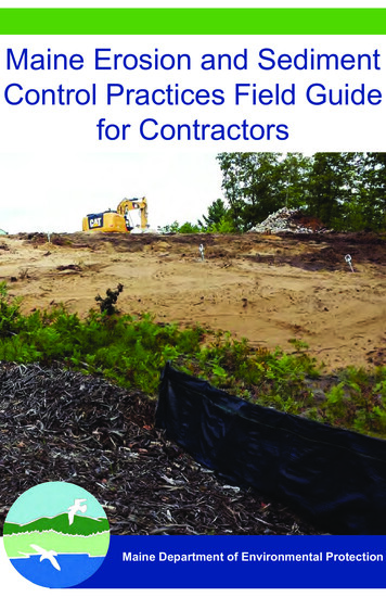
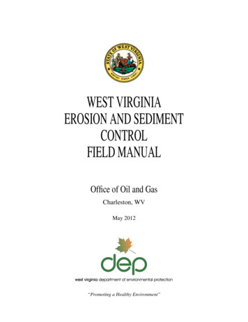
boulders, and debris. All such material will be disposed of by stacking, piling, windrowing, burning (inaccordance with WV Forest Fire Laws), removal from site, or other methods approved by the Inspector.2. Clearing of vegetation should be kept to the minimum necessary for construction plus the installation ofsediment controls.3. Road surface stabilization may be required in excessively wet or soft areas, by use of stone and/or stoneand fiber matting.4. When crossing pipelines or other underground utilities, adequate protection should be provided. For assistance in location underground utilities in WV call 1-800-245-4848 (Miss Utility of WV).5. When leaving a County or State Road Right-of-Way, a “Road Approach Permit” is required by the WVDivision of Highways. Refer to the DOH Manual for specifications.2. Drainage DitchDescription: An open drainage ditch constructed to a specific size and grade, along the road, to collect and convey surface water.a. Design Criteria:1. Ditch side slopes will not be steeper than 2:1, when excavated in soil. Refer to Table II-1 for allowableside slopes in other types of material.2. For allowable velocities, refer to Table II-2. Capacity of ditch shall be based on handling the expectedacreage of drainage. Minimum depth shall be 1 foot.3. Cross section of the ditch shall be V-shaped.4. All ditches should have erosion protection and/or stabilizing measures (see Figure II-6).5. Ditch stabilizing measures can be seeding and mulching, rock ditch check dams, and lining with stone orfabric, etc., depending upon ditch grade and expected velocity.6. Ditch outlets shall have erosion and sediment control structures.FIGURE II-1: Cross Drain/Water bar9
3. Cross Drain/Water BarDescription: An open ditch, constructed across the roadway, to carry off road surface water. They are not intended to replace culverts. See Figure II-1.a. Design Criteria:1. Minimum depth – 8 inches2. Minimum width – 2 feet3. Ditch will be angled approximately 30 degrees at a grade of ½ inch per foot of length.4. Velocity will not exceed the permissible velocity listed for the particular soil type. See Table II-2.5. Proper outlet protection will be provided to prevent erosion and control sedimentation from the ditch discharge. Material for the outlet can be rock, logs, concrete, or metal with the appropriate sediment barrier.6. Stabilization: Cross drains may need to be lined with erosion resistant materials, such as rock riprap. Rockused for riprap must be hard, angular and of a quality resistant to weathering and disintegration.7. Spacing: Refer to Table II-3.4. Broad-Based DipDescription: A constructed dip or swale, across the road surface, sloped to the outslope for drainage of the roadsurface. See Figure II-2.a. Design Criteria:1. Maximum road grade on which dips can be constructed is 10%2. A 3% reverse grade should be constructed in the existing roadbed, by cutting upgrade of the dip location.3. Broadbased dip should be armored with stone to withstand expected traffic.4. Drainage outlet protection shall be provided with appropriate sediment barrier structures.5. Spacing: Refer to Table II-4.FIGURE II-2 – Broad-Based Drainage Dip5. Diversion Ditch – TemporaryDescription: A channel or ridge constructed across a slope for diverting surface runoff. See Figure II-3.a. Purpose: To intercept surface water before it enters an erodible area and convey the runoff to a safe outlet.b. Design Criteria:1. For drainage areas less than 10 acres (see Figure II-3)a. Minimum depth – 18 inchesb. Minimum top width – 8 feetc. Maximum ditch grade – 2 percentd. Ditch outlets shall have erosion and sediment control. (See sediment barrier designs).2. Drainage area greater than 10 acresa. Capacity of ditch should handle a 2-year frequency storm, 24-hour duration. For further designinformation, contact the local Natural Resource Conservation Service Field Office.b. Velocity of water will not be greater than the permissible shown in Table II-2.3. Diverted run-off must outlet to a stabilized area.4. All ditches should have erosion protection and/or stabilizing measures as well as outlet protection.10
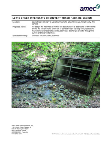
FIGURE II-3 – Diversion Ditch – Temporary6. CulvertDescription: Buried pipe, under the roadway, to carry water from the ditches and natural drainage ways.See Figures II-4.a. Type Material1. Steel2. Aluminum3. Concrete4. Plasticb. Design Criteria:1. Minimum size diameter will be 12 inches.2. For culvert sizes, based on drainage areas, refer to Table II-6.3. Culverts will be located at approximately 30 degrees downgrade.4. Culvert grade shall not be less than ½ inch per foot of length.5. Culverts will have at least 12 inches of soil cover, or ½ pipe diameter, whichever is greater. Additionalstabilization using crushed stone cover may be required to keep culvert from being damaged by heavytraffic.6. Culverts will have adequate headwalls or drop inlets, at their inlet areas, at least as wide and deep as thediameter of the culvert.7. Outlet protection is needed to prevent erosion from the culvert discharge. Fill slope protection can beaccomplished with riprap or, when necessary, down drain pipe. Riprap needs to be grouted on steep orlengthy fill slopes.8. Situations may warrant the use of “open top culverts” in some areas.9. Culvert Spacing: Refer to Table II-7.11
FIGURE II-4 – Ditch Relief Culvertc. Construction Specifications:1. Culverts will be installed to a specified line and grade.2. Ditch will be excavated to a depth and grade to ensure proper cover for the culvert.3. Ditch bottom will have a firm foundation for the culvert. Gravel may be used to stabilize the ditchbottom.4. The culvert will be backfilled with material free of large rocks, which may cause damage to it.5. Stone may be needed for further surface stabilization.6. Recommended installation is with a backhoe rather than a dozer.7. Culverts will have outlet protection (i.e. field rock or riprap, and sediment barriers) as well as natural filterstrip areas.8. Culverts with outlets onto lengthy fill slopes may require slope drains with outlet protection depending onthe steepness of the outslope.9. Riprap used as outlet protection must be hard, angular and of a quality resistant to weathering and disintegration. Riprap should be grouted on steep or lengthy fill slopes with a minimum thickness two times themaximum stone diameter, but not less than six inches.12
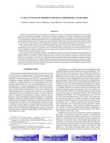
Figure II-5 Rock Ditch Check Dams7. Rock Check DamsDescription: Small temporary stone dams constructed across a ditch used to reduce the velocity of storm waterflows, thereby reducing erosion of the channel and trapping sediment. This practice is the replacement for thetraditionally misused hay/straw bales and silt fence ditch checks. Constructing a small dugout “trap” upstream ofthe structure can enhance the sediment trapping efficiency (see Figures II-5 and II-6).a. Conditions Where Practice AppliesThis practice, utilizing a combination of stone sizes, is limited to use in small open channels that drain 5 acresor less. It is NEVER used in live streams. Check dams can be useful in the following instances:1. Temporary ditches or swales2. Permanent ditches or swales that won’t be stabilized with permanent protection until the end of the project.3. Temporary or permanent ditches and swales which need protection during the establishment of grass linings.4. This practice is NOT a substitute for major perimeter trapping measures such as a SEDIMENT TRAP or aSEDIMENT BASIN.b. Construction SpecificationsNo formal design is required for a check dam however the following conditions should be adhered to.1. The drainage area of the ditch or swale being protected shall not exceed 2 acres when 2 to 4 inch aggregateis used alone; and shall not exceed 5 acres when a combination of 4 to 8 inch aggregate (added for stability) and the smaller aggregate is used. Refer to drawing for orientation of stone and a cross-sectional viewof the measure. An effort should be made to extend the stone to the top of channel banks.2. The maximum height of the dam should be 3.0 feet.3. The center of the check dam must be at least 6 inches lower than the outer edges. This is the single mostimportant aspect in the proper installation of the rock check dam. High flows must go over the center ofthe dam, not around the edges where severe erosion can occur.13
FIGURE II-6 – Sediment and Erosion Control for Access Roads8. Sediment Control BarriersDescription: A temporary restriction or barrier across a slope, at the toe of a slope, or at drainage outlets designedto trap sediment from a disturbed area by retarding and filtering water runoff. See Figure II-7, 8, 10, 11, 11a, band c.a. Types of Barriers1. Vegetative Filter Strip2. Silt fences14
3. Brush Barriers4. Temporary earth or rock barriers5. Sediment trap or basin6. Compost filter Socks7. Straw Balesb. Construction Specifications:1. Vegetative filter strip: A natural vegetative strip, left undisturbed, between the disturbed constructionarea and any surface water. The filter strip of vegetation acts as a buffer area to catch sediment before itenters the surface water. The width of the filter strip needed depends on the slope of the land and the typeof vegetation on the filter strip. Refer to Table II-8. A vegetative filter strip cannot always be used as astand alone sediment control, but should be used in conjunction with other sediment retainment structures,silt fences, filter socks, etc.2. Silt fence: Silt fences should be placed on the contour. Fence posts shall not be spaced greater than 10feet apart. If woven wire fence is used, it shall be fastened securely on the upstream side of the fenceposts. Filter cloth, when used, shall be secured on the upstream side of the fence posts and anchored atthe bottom. The filter cloth shall be embedded in the soil at least 4 inches and the soil compacted aroundit. Silt fences are not for concentrated flows. In areas where concentrated flows can be expected, use armored diversions and sediment traps. In ditches or swales rock check dams should be used. See silt fencesFigures II-11, 11a, b and c.Figures II-7 Sediment Barrier Examples15
3. Brush barriers: Brush barriers shall be a minimum of 3 feet in height and 5 feet in width at the base.Brush barriers are perimeter sediment control structures constructed of small tree branches, root mats,stone, or other debris left over from site clearing. They may be constructed as single pile units or windrowed, along the contour or at the base of a slope. The brush should be cut so it can be compactedsomewhat tightly together. Sizes of brush barriers may vary considerably based upon the amount of material available. Brush barrier effectiveness can be greatly increased with the use of a fabric cover on theup-slope side of the brush barrier. The brush barrier can be very effective at stopping large debris, rocks,stumps, but may need backed up with a silt fence to trap sediment.4. Earth or rock barriers: Earth or rock barriers should not be more than 2 feet in height and have sideslopes of 3:1 or less.5. Sediment trap basin: A sediment trap is a temporary ponding area formed by constructing an embankment or excavation at the outlet of ditches and other perimeter sediment controls that will trap the flow ofsediment- laden runoff. Sediment traps are appropriate for drainage areas of five acres or less. A sediment basin should be used for drainage areas of more than five acres.6. Compost filter sock: A compost filter sock is a mesh tube filled with composted material that is placedperpendicular to sheet-flow runoff to control erosion and retain sediment from disturbed areas. A filtersock can be used as a perimeter control in the place of the traditional silt fence or straw bales. The smallerdiameter filter socks can be used to slow ditch water drainage and for inlet protection.7. Straw bales: Straw or hay bales have historically been used on construction sites for erosion and sediment control and perimeter sediment control, but straw bales have limitations. Straw bales are not able towithstand high flows, have a limited lifespan, and care must be taken during placement and installationto avoid failure from undercutting, overtopping, and end-running. Another factor to consider is that strawbales and especially hay bales may introduce undesirable non-native plants to the area.9. Erosion ControlDescription: Erosion is the gradual wearing away of soils by the action of water and wind. Protection of bare soilsfrom the wearing effects of water and wind, especially topsoil, decreases sediment loss.Example: Hydroseeding16
a.Types of Erosion Control1. Preserving Existing Vegetation -- Vegetative Filter Strip pg. 152. Temporary Seeding -- pg. 363. Permanent Seeding -- pg. 374. Outlet Protection -- pg. 175. Rock Check Dams -- pg. 136. Right of Way Diversions -- pg. 107. Riprap -- pg. 178. Rolled Erosion Control Products -- pg. 1610. Outlet Protection: All culvert outlets shall have some type of energy dissipating structure for erosion protectionsuch as: boulders, tree stumps or rock riprap.a. Boulders (large ungraded field stone or shot rock).b. Tree stumps larger than 6 inch diameter.c. Rock riprap consisting of fieldstone or rough un-hewn quarry stone; must be hard, angular and of a qualityresistant to weathering and disintegration. The minimum thickness shall be two times the maximum stonediameter, but not less than six inches.Figure II-8 Outlet Protection11. Stream Crossing – TemporaryDescription: A temporary structural span installed across a flowing watercourse, for use of construction traffic,drilling equipment, etc., so as to provide a means to cross the stream without damaging the stream and to preventsediment from entering the stream (see Figure II-12).a. Types:1. Culverts2. Bridge3. Stone base17
b. Design Criteria:1. The structure shall be large enough to handle a 1-year frequency storm, 24 hour duration.2. Depth of cover over culverts shall be ½ the diameter of the culverts used or 12 inches, whichever isgreater.3. Multi-culverts should be installed with spaces between them, equal to ½ the pipe diameter.4. Low water crossings may be used, if protected when overflowing occurs. This can be accomplished byusing rock and concrete.5. Cross cribbing of the downstream side of culvert installations may be needed to aid in reducing structuraldamage during high velocity water overflow periods.6. If culverts or bridges are not used and a stone base doesn’t exist, stone shall be installed, with the entranceand exit being stoned for approximately 100 feet.7. Ditch line exit points at stream crossings must have sediment controls.Stream crossing structures may require a “Stream Activity Permit” from the WV Office of Land and Streams(formally the Public Lands Corporation) of the West Virginia Division of Natural Resources (304) 558-3225and Fax (304) 558-6048 and a permit from the Army Corps of Engineers.FIGURE II-9: Stream Crossing – Temporary, with Culvert12. Sediment Traps – TemporaryDescription: A trap constructed to collect water runoff, with adequate retention time to allow sediment to settle.a. Design Criteria:1. Water containing sediment from any disturbed area is diverted to the trap.2. The sediment trap shall have adequate overflow pipes and/or spillways installed, with outlet protection.18
3. The area of drainage is used to calculate the sizing and construction of the sediment trap . The maximumacreage that a sediment trap is designed to handle is five acres. For areas larger than five acres morethan one sediment trap should be used, or a sediment basin design could be needed.4. The sediment trap should have a storage volume of 3600 cubic feet per acre of drainage area. Half of thevolume must be in the form of a permanent pool or wet storage to provide a stable-settling medium. Theremaining half must be in the form of a drawdown or dry storage, which provides extended settling time.5. The embankment should not exceed 5 feet in height. The recommended minimum width at the top of theembankment should be equal to the height of the embankment.6. The recommended inside embankment slope should be a 2:1 slope or flatter. The recommended outsideembankment slope should be a 3:1 or flatter.7. The sediment trap must have a stabilized outlet. If a stone outlet is used the crest of the stone outlet mustbe at least 1 foot below the top of the embankment. The stone for the outlet should be a combination ofcoarse aggregate and rock riprap separated from the earthen embankment by a geotextile.Example: Sediment Trap19
FIGURE II-10: Brush Pile Sediment BarrierFIGURE II-11: Silt Fence Sediment BarrierStandard Filter Fabric Fence must be placed at existing level grade. Both ends of the barrier must be extended at least 8feet up slope at 45 degrees to the main barrier alignment.Sediment shall be removed when accumulations reach 1/2 the above ground height of the fe
Rip rap h. Straw bales 9. Determine revegetation needs: a. Temporary vegetation b. Permanent vegetation B. Construction and Reclamation Plan Preparation The Construction and Reclamation Plan is drawn up and submitted on Form WW-9 to the DEP, Office of Oil and Gas, with a well work permi