Transcription
Multi2Sim: A Simulation Framework forCPU-GPU ComputingRafael Ubal†ubal@ece.neu.eduByunghyun Jang‡ bjang@cs.olemiss.eduDana Schaa†dschaa@ece.neu.edu†Electrical and Computer Engineering Dept.Northeastern University360 Huntington Ave., Boston, MA 02115ABSTRACTAccurate simulation is essential for the proper design and evaluation of any computing platform. Upon the current move towardthe CPU-GPU heterogeneous computing era, researchers need asimulation framework that can model both kinds of computing devices and their interaction. In this paper, we present Multi2Sim, anopen-source, modular, and fully configurable toolset that enablesISA-level simulation of an x86 CPU and an AMD Evergreen GPU.Focusing on a model of the AMD Radeon 5870 GPU, we addressprogram emulation correctness, as well as architectural simulationaccuracy, using AMD’s OpenCL benchmark suite. Simulation capabilities are demonstrated with a preliminary architectural exploration study, and workload characterization examples. The projectsource code, benchmark packages, and a detailed user’s guide arepublicly available at www.multi2sim.org.1. INTRODUCTIONGPUs have become an important component of High Performance Computing (HPC) platforms by accelerating the ever demanding data-parallel portions of a wide range of applications. Thesuccess of GPU computing has made microprocessor researchers inboth academia and industry believe that CPU-GPU heterogeneouscomputing is not just an alternative, but the future of HPC. Now,GPUs are showing up as integrated accelerators for general purposeplatforms [8, 5, 9]. This move attempts to leverage the combinedcapabilities of multi-core CPU and many-core GPU architectures.As CPU-GPU heterogeneous computing research gains momentum, the need to provide a robust simulation environment becomes This work was done while the author was with AMD.Permission to make digital or hard copies of all or part of this work forpersonal or classroom use is granted without fee provided that copies arenot made or distributed for profit or commercial advantage and that copiesbear this notice and the full citation on the first page. To copy otherwise, torepublish, to post on servers or to redistribute to lists, requires prior specificpermission and/or a fee.PACT’12, September 19–23, 2012, Minneapolis, Minnesota, USA.Copyright 2012 ACM 978-1-4503-1182-3/12/09 . 15.00.Perhaad Mistry†pmistry@ece.neu.eduDavid Kaeli†kaeli@ece.neu.edu‡Computer and Information Science Dept.University of MississippiP. O. Box 1848, University, MS 38677more critical. Simulation frameworks provide a number of benefitsto researchers. They allow pre-silicon designs to be evaluated andperformance results to be obtained for a range of design points. Anumber of CPU simulators supporting simulation at the ISA levelhave been developed [11, 14] and successfully used in a range ofarchitectural studies. Although there are tools that are currentlyavailable for simulating GPUs at the intermediate language level(e.g., PTX) [12, 13], the research community still lacks a publiclyavailable framework integrating both fast functional simulation andcycle-accurate detailed architectural simulation at the ISA level thatconsiders a true heterogeneous CPU-GPU model.In this paper we present Multi2Sim, a simulation framework forCPU-GPU computing. The proposed framework integrates a publicly available model of the data-parallel AMD Evergreen GPUfamily [3]1 with the simulation of superscalar, multi-threaded, andmulticore x86 processors. This work also offers important insightinto the architecture of an AMD Evergreen GPU, by describing ourmodels of instruction pipelines and memory hierarchy, to a deeperextent than previous public work, to the best of our knowledge, hasdone before.Multi2Sim is provided as a Linux-based command-line toolset,designed with an emphasis on presenting a user-friendly interface.It runs OpenCL applications without any source code modifications, and provides a number of instrumentation capabilities thatenable research in application characterization, code optimization,compiler optimization, and hardware architecture design. To illustrate the utility and power of our toolset, we report on a wide rangeof experimental results based on benchmarks taken from AMD’sAccelerated Parallel Processing (APP) SDK 2.5 [1].The rest of this paper is organized as follows. Section 2 introduces the functional simulation model in Multi2Sim. Section 3presents the Evergreen GPU architecture and its simulation. Section 4 reports our experimental evaluation. We summarize relatedwork in Section 5, and conclude the paper in Section 6.1AMD has used the Evergreen ISA specification for the implementation of its mainstream Radeon 5000 and 6000 series of GPUs.
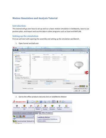
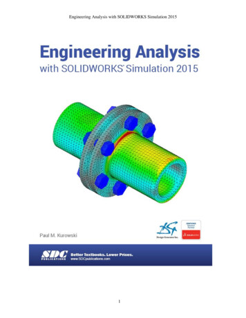
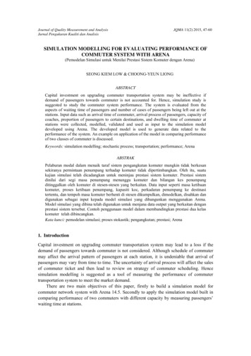
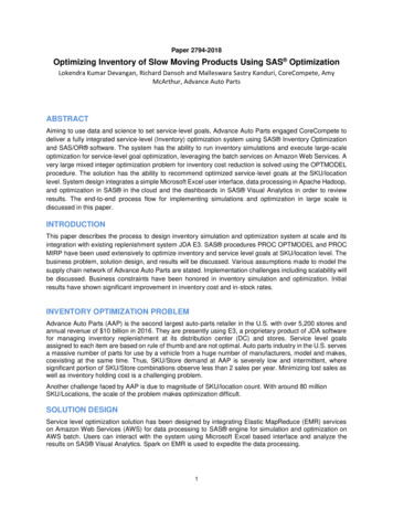
2. THE MULTI2SIM PROJECTThe Multi2Sim project started as a free, open-source, cycleaccurate simulation framework targeting superscalar, multithreaded, and multicore x86 CPUs. The CPU simulation framework consists of two major interacting software components: thefunctional simulator and the architectural simulator. The functional simulator (i.e., emulator) mimics the execution of a guestprogram on a native x86 processor, by interpreting the programbinary and dynamically reproducing its behavior at the ISA level.The architectural simulator (i.e., detailed or timing simulator) obtains a trace of x86 instructions from the functional simulator, andtracks execution of the processor hardware structures on a cycleby-cycle basis.The current version of the CPU functional simulator supports theexecution of a number of different benchmark suites without anyporting effort, including single-threaded benchmark suites (e.g.,SPEC2006 and Mediabench), multi-threaded parallel benchmarks(SPLASH-2 and PARSEC 2.1), as well as custom self-compileduser code. The architectural simulator models many-core superscalar pipelines with out-of-order execution, a complete memoryhierarchy with cache coherence, interconnection networks, and additional components.Multi2Sim integrates a configurable model for the commercialAMD Evergreen GPU family (e.g., Radeon 5870). The latest releases fully support both functional and architectural simulation ofa GPU, following the same interaction model between them as forCPU simulation. While the GPU emulator provides traces of Evergreen instructions, the detailed simulator tracks execution timesand architectural state.All simulated programs begin with the execution of CPU code.The interface to the GPU simulator is the Open Compute Language(OpenCL). When OpenCL programs are executed, the host (i.e.,CPU) portions of the program are run using the CPU simulationmodules. When OpenCL API calls are encountered, they are intercepted and used to setup or begin GPU simulation.2.1 The OpenCL Programming ModelOpenCL is an industry-standard programming framework designed specifically for developing programs targeting heterogeneous computing platforms, consisting of CPUs, GPUs, andother classes of processing devices [7]. OpenCL’s programmingmodel emphasizes parallel processing by using the single-programmultiple-data (SPMD) paradigm, in which a single piece of code,called a kernel, maps to multiple subsets of input data, creating amassive amount of parallel execution.Figure 1 provides a view of the basic execution elements hierarchy defined in OpenCL. An instance of the OpenCL kernel is calleda work-item, which can access its own pool of private memory.Work-items are arranged into work-groups with two basic properties: i) those work-items contained in the same work-group canFigure 1: OpenCL programming and memory model.perform efficient synchronization operations, and ii) work-itemswithin the same work-group can share data through a low-latencylocal memory. The totality of work-groups form the ND-Range(grid of work-item groups) and share a common global memory.2.2OpenCL SimulationFigure 2: Comparison of software modules of an OpenCL program: native AMD GPU based heterogeneous system versusMulti2Sim simulation framework.The call stack of an OpenCL program running on Multi2Sim differs from the native call stack starting at the OpenCL librarycall, as shown in Figure 2. When an OpenCL API function call is issued, our implementation of the OpenCL runtime(libm2s-opencl.so) handles the call. This call is interceptedby the CPU simulation module, which transfers control to the GPUmodule as soon as the guest application launches the device kernelexecution. This infrastructure allows unmodified x86 binaries (precompiled OpenCL host programs) to run on Multi2Sim with totalbinary compatibility with the native environment.3.ARCHITECTURAL SIMULATION OFAN AMD EVERGREEN GPUThis section presents the architecture of a generic AMD Evergreen GPU device, focusing on hardware components devoted togeneral purpose computing of OpenCL kernels. As one of the novelties of this paper, the following block diagrams and descriptionsprovide some insight into the instruction pipelines, memory components, and interconnects, which tend to be kept private by the major GPU vendors, and remain undocumented in currently availabletools. All presented architectural details are accurately modeled onMulti2Sim, as described next.3.1The Evergreen GPU ArchitectureA GPU consists of an ultra-threaded dispatcher, an array ofindependent compute units, and a memory hierarchy. The ultrathreaded dispatcher processes the ND-Range and maps waitingwork-groups onto available compute units. Once a work-group isassigned to a compute unit, it remains in the compute unit until itsexecution completes. As a work-group executes, work-items fetchand store data through the global memory hierarchy, formed of twolevels of cache, interconnects, and memory controllers. Figure 3ashows a block diagram of the Evergreen family compute device.A compute unit consists of three execution engines, a local memory, and a register file. The three execution engines, called controlflow (CF), arithmetic-logic (ALU), and texture (TEX) engines, aredevoted to execute different portions of an OpenCL kernel binary,referred to as CF, ALU, and TEX clauses, respectively (see Section 3.2). A block diagram of the compute unit is illustrated inFigure 3b.
Figure 4: Example of AMD Evergreen assembly code: (a) mainCF clause instruction counter, (b) internal clause instructioncounter, (c) ALU clause, (d) TEX clause.Figure 3: Block diagram of the GPU architecture.The ALU engine contains a set of stream cores, each devoted tothe execution of one work-item’s arithmetic operations. ALU instructions are organized as 5-way VLIW bundles, created at compile time. Each instruction in a VLIW bundle is executed on one ofthe 5 VLIW lanes forming the stream core.An Evergreen GPU defines the concept of a wavefront as agroup of work-items executing in a Single-Instruction MultipleData (SIMD) fashion. Each instruction is executed concurrently byevery work-item comprising a wavefront, although each work-itemuses its private data for the computations. This model simplifies instruction fetch hardware by implementing a common front-end fora whole wavefront.3.2 The Evergreen Instruction Set Architecture (ISA)When the GPU functional simulator receives the OpenCL kernel to execute, an emulation loop starts by fetching, decoding, andexecuting Evergreen instructions. The basic format of the AMDEvergreen ISA can be observed in the sample code from Figure 4.Evergreen assembly uses a clause-based format. The kernel execution starts with a CF instruction. CF instructions affect the mainprogram control flow (such is the case for CF instruction 03), writedata to global memory (04), or transfer control to a secondaryclause, such as an ALU clause (00, 02), or a TEX clause (01).ALU clauses contain instructions performing arithmetic-logic operations and local memory accesses, while TEX clauses are exclusively devoted to global memory read operations.ALU instructions are packed into VLIW bundles. A VLIW bundle is run one at a time on a stream core, where each ALU instruction label reflects the VLIW lane assigned to that instruction. AnALU instruction operand can be any output from the previouslyexecuted VLIW bundle using the Previous Vector (PV) or the Pre-vious Scalar (PS) special registers. Finally, constant memory is anadditional globally accessible storage initialized by the CPU, whichcan also be used as ALU instruction operands (KC).From our discussion above of Evergreen ISA characteristics,we can observe a couple of important differences from workingwith higher level intermediate languages, such as AMD’s IL [4] orNVIDIA’s PTX [6]. For example, in AMD’s Evergreen ISA thereis a limited number of general purpose registers, so there are restrictions on how to form VLIW bundles, and there are specificrules to group machine instructions forming clauses. In general,there are many properties of the ISA run directly by the machinethat need not be considered working with an intermediate language.Thus, significant performance accuracy can be gained with ISAlevel simulation.3.2.1Kernel Execution ModelWhen an OpenCL kernel is launched by a host program, the NDRange configuration is provided to the GPU. Work-groups are thencreated and successively assigned to compute units when they haveavailable execution resources. The number of work-groups that canbe assigned to a single compute unit is determined by four hardwarelimitations: i) the maximum number of work-groups supported percompute unit, ii) the maximum number of wavefronts per computeunit, iii) the number of registers on a compute unit, and iv) theamount of local memory on a compute unit. Maximizing the number of assigned work-groups per compute unit is a performancesensitive decision that can be evaluated on Multi2Sim.Each work-group assigned to a compute unit is partitioned intowavefronts, which are then placed into a ready wavefront pool. TheCF engine selects wavefronts from the wavefront pool for execution, based on a wavefront scheduling algorithm. A new wavefrontstarts running the main CF clause of the OpenCL kernel binary,and subsequently spawns secondary ALU and TEX clauses. Thewavefront scheduling algorithm is another performance sensitiveparameter, which can be evaluated with Multi2Sim.When a wavefront is extracted from the pool, it is only insertedback in when the executed CF instruction completes. This ensuresthat there is only a single CF instruction in flight at any time for a
given wavefront, avoiding the need for branch prediction or speculative execution in case flow control is affected. The performancepenalty for this serialization is hidden by overlapping the executionof different wavefronts. Determining the extent to which overlapping execution is occurring and the cause of bottlenecks are additional benefits of simulating execution with Multi2Sim.3.2.2 Work-Item DivergenceIn a SIMD execution model, work-item divergence is side-effectgenerated when a conditional branch instruction is resolved differently for any work-items within a wavefront. To address work-itemdivergence present during SIMD execution, the Evergreen ISA provides each wavefront with an active mask. The active mask is a bitmap, where each bit represents the active status of an individualwork-item in the wavefront. If a work-item is labeled as inactive,the result of any arithmetic computation performed in its associatedstream core is ignored, preventing the work-item from changing thekernel state.This work-item divergence strategy attempts to converge allwork-items together across all possible execution paths, allowingonly those active work-items whose conditional execution matchesthe currently fetched instruction flow to continue execution. Tosupport nested conditionals and procedure calls, an active maskstack is used to push and pop active masks, so that the active maskat the top of the stack always represents the active mask of the currently executing work-items. Using Multi2Sim, statistics related towork-item divergence are available to researchers (see Section 4.3).3.3 The Instruction PipelinesIn a compute unit, the CF, ALU, and TEX engines are organized as instruction pipelines. Figure 5 presents a block diagramof each engine’s instruction pipeline. Within each pipeline, decisions about scheduling policies, latencies, and buffer sizes mustbe made. These subtle factors have performance implications, andprovide another opportunity for researchers to benefit from experimenting with design decisions within Multi2Sim.The CF engine (Figure 5a) runs the CF clause of an OpenCLkernel. The fetch stage selects a new wavefront from the wavefrontpool on every cycle, switching among them at the granularity ofone single CF instruction. Instructions from different wavefrontsare interpreted by the decode stage in a round-robin fashion. Whena CF instruction triggers a secondary clause, the corresponding execution engine (ALU or TEX engine) is allocated, and the CF instruction remains in the execute stage until the secondary clausecompletes. Other CF instructions from other wavefronts can be executed in the interim, as long as they do not request a busy execution engine. CF instruction execution (including all instructions runin a secondary clause, if any) finishes in order in the complete stagestage. The wavefront is returned to the wavefront pool, making itagain a candidate for instruction fetching. Global memory writesare run asynchronously in the CF engine itself, without requiring asecondary engine.The ALU engine is devoted to the execution of ALU clausesfrom the allocated wavefront (Figure 5b). After the fetch and decode stages, decoded VLIW instructions are placed into a VLIWbundle buffer. The read stage consumes the VLIW bundle andreads the source operands from the register file and/or local memory for each work-item in the wavefront. The execute stage issuesan instance of a VLIW bundle to each of the stream cores every cycle. The number of stream cores in a compute unit might be smallerthan the number of work-items in a wavefront. Thus, a wavefrontis split into subwavefronts, where each subwavefront contains asmany work-items as there are stream cores in a compute unit. Theresult of the computation is written back to the destination operands(register file or local memory) at the write stage.The TEX engine (Figure 5c) is devoted to the execution of globalmemory fetch instructions in TEX clauses. The TEX instructionbytes are stored into a TEX instruction buffer after being fetchedand decoded. Memory addresses for each work-item in the wavefront are read from the register file and a read request to the globalmemory hierarchy is performed at the read stage. Completedglobal memory reads are handled in order by the write stage. Thefetched data is stored into the corresponding locations of the register file for each work-item. The lifetime of a memory read is modeled in detail throughout the global memory hierarchy, as specifiedin the following sections.3.4Memory SubsystemThe GPU memory subsystem contains different components fordata storage and transfer. With Multi2Sim, the memory subsystem is highly configurable, including customizable settings for thenumber of cache levels, memory capacities, block sizes, number ofbanks, and ports. A description of the memory components for theEvergreen model follows:Register file (GPRs). Multi2Sim provides a model with no contention for register file accesses. In a given cycle, the register can beaccessed by the TEX and ALU engines simultaneously by different wavefronts. Work-items within and among wavefronts alwaysaccess different register sets.Local Memory. A separate local memory module is present ineach compute unit, and is modeled in Multi2Sim with a configurable latency, number of banks, ports, and allocation chunk size.In an OpenCL kernel, accesses to local memory are defined by theprogrammer by specifying a variable’s scope, whose accesses arethen compiled into distinct assembly instructions. Contention to local memory is modeled by serializing accesses to the same memorybank whenever no read or write port is available. Also, memoryaccess coalescing is considered by grouping those accesses fromdifferent work-items to the same memory block.Global memory. The GPU global memory is accessible by allcompute units. It is presented to the programmer as a separatememory scope, and implemented as a memory hierarchy managedby hardware in order to reduce access latency. In Multi2Sim, theglobal memory hierarchy has a configurable number of cache levelsand interconnects. A possible configuration is shown in Figure 6a,using private L1 caches per compute unit, and multiple L2 cachesthat are shared between subsets of compute units. L1 caches provide usually a similar access time as local memory, but they aremanaged transparently by hardware, similarly to how a memoryhierarchy is managed on a CPU.Interconnection networks. Each cache in the global memoryhierarchy is connected to the lower-level cache (or global memory)using an interconnection network. Interconnects are organized aspoint-to-point connections using a switch, whose architecture blockdiagram is presented in Figure 6b. A switch contains two disjointinner subnetworks, each devoted to package transfers in oppositedirections.Cache access queues. Each cache memory has a buffer whereaccess requests are enqueued, as shown in Figure 6c. On one hand,access buffers allow for asynchronous writes that prevent stalls ininstruction pipelines. On the other hand, memory access coalescing is handled in access buffers at every level of the global memory hierarchy (both caches and global memory). Each sequenceof subsequent entries in the access queue reading or writing to thesame cache block are grouped into one single actual memory access. The coalescing degree depends on the memory block size,
Figure 5: Block diagram of the execution engine pipelines.Figure 6: Components of the GPU global memory hierarchy, as modeled in Multi2Sim.the access queue size, and the memory access pattern, and is a veryperformance sensitive metric measurable with Multi2Sim.4. EXPERIMENTAL EVALUATIONThis section presents a set of experiments aimed at validating anddemonstrating the range of functional and architectural simulationfeatures available with Multi2Sim. All simulations are based ona baseline GPU model resembling the commercial AMD Radeon5870 GPU, whose hardware parameters are summarized in Table 1.For the simulator performance studies, simulations were run ona machine with four quad-core Intel Xeon processors (2.27GHz,8MB cache, 24GB DDR3). Experimental evaluations were performed using a subset of the AMD OpenCL SDK [1] applications,representing a wide range of application behaviors and memoryaccess patterns [16]. The applications discussed in this paper arelisted in Table 2, where we include a short description of the programs and the corresponding input dataset characteristics.4.1ValidationOur validation methodology for establishing the fidelity of theGPU simulator considered the correctness of both the functionaland architectural simulation models, though we follow two different validation methodologies. For the functional simulator, the correctness of the instruction decoder is validated by comparing thedisassembled code to the Evergreen output that is generated by theAMD compiler. We also validate the correctness of each benchmark’s execution by comparing the simulated application outputwith the output of the application run directly on the CPU. All simulations generate functionally correct results for all programs studied and input problem sets.Regarding the fidelity of the architectural model, Multi2Sim’sperformance results have been compared against native executionperformance (native here refers to the actual Radeon 5870 hardware), using ten different input sizes within the ranges shown inTable 2 (column Input Range). Since our architectural model iscycle-based, and the native execution is measured as kernel execution time, it is challenging to compare our metrics directly. To con-
86565302520154410331234 5 6 7Input Set Number8910a) Simulated execution time reported byMulti2Sim.om243576Input Set Number8910Bin0 1ial115022035DCTMatixMultiplicationSobel FilterBinomial Option7Simulation inaccuracy (%)7OpBit tionsonicSMaortrixMu D tltip CTlicaSo tionbelFiltScan U erLa RNrge GArrRa aysdixSAv orterageDCTMatixMultiplicationSobel FilterBinomial OptionNative Execution Time (ms)Simulated Execution Time (ms)8c) Average error percentage between theb) Native execution time on the AMD Radeon native execution time and simulated executiontime for APP SDK benchmarks.5870.Figure 7: Validation for the architectural simulation, comparing simulated and native absolute execution times.!/ ! 0)/)/%)'%-)' ' ,##*( ,%)(& %"!#'.'1).12!Figure 8: Validation for architectural simulation, comparing trends between simulated and native execution times.vert simulated cycles into time, we use the documented ALU clockfrequency of 850MHz of the 5870 hardware. The native executiontime is computed as the average time of 1000 kernel executions foreach benchmark. Native kernel execution time was measured using the AMD APP profiler [2]. The execution time provided by theAPP profiler does not include overheads such as kernel setup andhost-device I/O [2].Figure 7a and Figure 7b plot simulated execution time and nativeexecution time performance trends, respectively (only four benchmarks are shown for clarity). Figure 7c shows the percentage difference in performance for a larger selection of benchmarks. Thevalue shown for each benchmark in Figure 7c is the average ofthe absolute percent error for each input of the benchmark. Forthose cases where simulation accuracy decreases, Figure 8 showsdetailed trends, leading to the following analysis.In Figure 8a, we show the correlation between the native execution time and the simulated execution time for the studied benchmarks. For some of the benchmarks (e.g., Histogram or RecursiveGauss), execution times vary significantly. However, we still seea strong correlation between each of the native execution pointsand their associated simulator results for all benchmarks. In otherwords, a change in the problem size for a benchmark has the samerelative performance impact for both native and simulated executions. The linear trend-line is represented using a curve-fitting algorithm that minimizes the squared distances between every datapoint and itself. For the benchmarks that are modeled accuratelyusing the simulator, the data points lie on the 45 line. The reason for the occurrence of divergent slopes can be attributed to thelack of precise representation of the memory hierarchy in the 5870GPU, including the following factors:Specialized Memory Path Design. The AMD Radeon 5870consists of two paths from compute units to memory [2], each withdifferent performance characteristics. The fast path performs onlybasic operations, such as loads and stores for 32-bit data types. Thecomplete path supports additional advanced operations, includingatomics and stores for sub-32-bit data types. This design has beendeprecated in later GPU architectures for a more conventional layout [17], which is similar to the one currently implemented inMulti2Sim.Cache Interconnects. The specification of the interconnectionnetwork between the L1 and L2 caches has not been published.We use an approximation where four L2 caches are shared betweencompute units (Table 1).
Table 1: Baseline GPU simulation parameters.Figure 9: Simulation slowdowns over native execution for functional and architectural simulation.Cache Parameters. The latency and associativity of the different levels of the cache hierarchy are not known. Some sourcesof simulation inaccuracy can be attributed to cache parameters, asshown in Figure 8, where the percent error is minimum for the caseswhere the native cache hit ratios and simulated cache hit ratios varythe least.4.2Table 2: List of OpenCL benchmarks used for experiments.Column Input base contains the baseline problem size used, andcolumn Input range contains the range of problem sizes usedduring simulator validation.Simulation SpeedFor the benchmarks used in this paper, Multi2Sim’s simulationoverhead is plotted in Figure 9 as a function of the slowdown overnative execution time. The average functional simulation slowdown is 8700 (113s), and the average architectural simulationtime is 44000 (595s). It should be noted that simulation timeis not necessarily related to native execution time (e.g., simulating one 100-cycle latency instruction is faster than simulating ten1-cycle instructions), so these results only aim to provide some representative samples of simulation overhead.Simulation performance has been also evaluated for an architectural simulation on GPGPUSim, an NVIDIA-based GPU simulator [10]. This simulator has been used as experimental support forrecent studies on GPU computing, exploring alternative memorycontroller implementations [18] and dynamic grouping of threads(work-items) to minimize thread divergence penalty [15], for example. To enable this comparison, the APP SDK benchmarks wereadapted to run on GPGPUSim. Figure 9c shows the performanceslowdown over native execution, which averages about 90000 (1350s).4.3Benchmark CharacterizationAs a case study of GPU simulation, this section presents a briefcharacterization of OpenCL benchmarks carried out on Multi2Sim,based on instruction classification, VLIW bundle occupancy, andcontrol flow divergence. These statistics are dynamic in nature,and are reported by Multi2Sim as part of its simulation reports.Figure 10a shows Evergreen instruction mixes executed by eachOpenCL kernel. The instruction categories are control flow instructions (jumps, stack operations, and synchronizations), globalmemory reads, global memory writes, local memory accesses, andarithmetic-logic operations. Arithmetic-logic operations form thebulk of executed instru
tional simulator (i.e., emulator) mimics the execution of a guest program on a native x86 processor, by interpreting the program binary and dynamically reproducing its behavior at the ISA level. The architectural simulator (i.e., detailed or timing simulator) ob-tains a trace of x86 instruc