Transcription
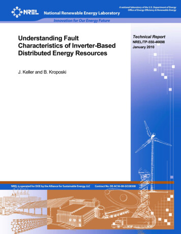
Understanding FaultCharacteristics of Inverter-BasedDistributed Energy ResourcesJ. Keller and B. KroposkiTechnical ReportNREL/TP-550-46698January 2010
Understanding FaultCharacteristics of Inverter-BasedDistributed Energy ResourcesJ. Keller and B. KroposkiPrepared under Task No. DRS8.1050National Renewable Energy Laboratory1617 Cole Boulevard, Golden, Colorado 80401-3393303-275-3000 www.nrel.govNREL is a national laboratory of the U.S. Department of EnergyOffice of Energy Efficiency and Renewable EnergyOperated by the Alliance for Sustainable Energy, LLCContract No. DE-AC36-08-GO28308Technical ReportNREL/TP-550-46698January 2010
NOTICEThis report was prepared as an account of work sponsored by an agency of the United States government.Neither the United States government nor any agency thereof, nor any of their employees, makes anywarranty, express or implied, or assumes any legal liability or responsibility for the accuracy, completeness, orusefulness of any information, apparatus, product, or process disclosed, or represents that its use would notinfringe privately owned rights. Reference herein to any specific commercial product, process, or service bytrade name, trademark, manufacturer, or otherwise does not necessarily constitute or imply its endorsement,recommendation, or favoring by the United States government or any agency thereof. The views andopinions of authors expressed herein do not necessarily state or reflect those of the United Statesgovernment or any agency thereof.Available electronically at http://www.osti.gov/bridgeAvailable for a processing fee to U.S. Department of Energyand its contractors, in paper, from:U.S. Department of EnergyOffice of Scientific and Technical InformationP.O. Box 62Oak Ridge, TN 37831-0062phone: 865.576.8401fax: 865.576.5728email: mailto:reports@adonis.osti.govAvailable for sale to the public, in paper, from:U.S. Department of CommerceNational Technical Information Service5285 Port Royal RoadSpringfield, VA 22161phone: 800.553.6847fax: 703.605.6900email: orders@ntis.fedworld.govonline ordering: http://www.ntis.gov/ordering.htmPrinted on paper containing at least 50% wastepaper, including 20% postconsumer waste
Abstract and KeywordsOne of the most important aspects of planning and operating an electrical power system is thedesign of protection systems that handle fault conditions. Protection engineers design protectionsystems to safely eliminate faults from the electric power system. One of the new technologiesrecently introduced into the electric power system is distributed energy resources (DER).Currently, inverter-based DER contribute very little to the power balance on all but a few utilitydistribution systems. A significant increase in DER is expected to come on line in the nearfuture. As the penetration level of DER increases, the effect of DER may no longer beconsidered minimal. As DER become prevalent in the distribution system, equipment ratingcapability and coordination of protection systems merit a closer investigation. This reportdiscusses issues and provides solutions for dealing with fault current contributions from inverterbased DER.Keywords:Distributed energy resources, distributed generation, inverter, fault, fault current, short circuit,low-voltage ride throughiii
Table of ContentsAbstract and Keywords . iiiList of Figures . vList of Tables . v1Introduction . 12Protection and Coordination Issues . 32.1Protective Relaying . 32.2Relay Coordination . 52.3DER Related Relaying . 73Short Circuit Analysis . 93.1Synchronous Machines . 133.2Induction Machines. 144Short Circuit Current Analysis of Inverter-Based DER . 164.1Background on Power Electronics . 164.1.1 PE Devices . 164.1.2 Applications . 174.2Prior Research on Inverter Based DER Fault Current . 184.3Fault Characteristics of Inverter-Based DER . 195Testing Methods for Determining Fault Contributions . 205.1Testing Background . 205.2Test Procedure . 205.3NREL Experimental Setup . 205.3.1 Test Procedure . 215.3.2 Test Results . 215.4Inverter Manufacturer’s Results . 236Low Voltage Ride-Through (LVRT) . 256.1Fault Ride Through Requirements for Large Generators . 256.1.1 Federal Energy Regulatory Commission . 256.1.2 American Wind Energy Association . 266.1.3 Western Electricity Coordinating Council . 266.1.4 North American Electric Reliability Council . 286.2IEEE 1547 Requirements . 306.2.1 German LVRT requirements for DER . 316.3LVRT Testing Requirements . 316.4LVRT Summary. 337Computer Modeling Techniques. 347.1Modeling and Simulation . 347.2Commercial Products . 358Conclusions and Future Recommendations . 388.1Conclusions . 388.2Future Recommendations . 399References . 40iv
List of FiguresFigure 1.Figure 2.Figure 3.Figure 4.Figure 5.Figure 6.Figure 7.Figure 8.Figure 9.Figure 10.Figure 11.Figure 12.Figure 13.Figure 14.Figure 15.Figure 16.Figure 17.Figure 18.Figure 19.Figure 20.Figure 21.Figure 22.Figure 23.Figure 24.Figure 25.Figure 26.Figure 27.Figure 28.DER Technologies . 2Typical electric power system single-line diagram . 3Input and output control of a protective relay . 4Electromechanical relay (Glover/Sarma) . 5Microprocessor relay . 5Example of a time current curve . 6Typical single-line diagram . 7Circuit model for asymmetrical fault current. 10AC symmetrical short-circuit current . 11Decaying DC offset short-circuit current. 12Total (DC and AC components) short-circuit asymmetrical current . 13Synchronous machine response to 3-phase fault (DC offset not shown) . 14Induction machine response to 3-phase fault . 15DER system and PE interface block diagram (Kroposki et al. 2006) . 16Test circuit single-line diagram . 21Pre-fault waveform of 1 kW inverter . 22Fault current test result of 1 kW inverter . 22Manufacturer’s 500 KVA inverter output short circuit test resultsbetween B-C phases . 23LVRT requirement per FERC Order No. 661 . 26WECC system performance criteria from Table W (WECC System PerformanceCriteria, TPL – WECC – 1 – CR, 2008) . 272005 WECC LVRT standard (Zavadil et al. 2005) . 272009 proposed WECC LVRT standard . 28NERC (RROs) members (IEEE Power and Energy Magazine 2005) . 29IEEE 1547 (Table 1) Interconnection system response to abnormal voltages . 30IEEE 1547 Interconnection system response to abnormal voltages from IEEE 1547(Table 1) . 30Germany’s new LVRT grid code. 31UL 1747 Table 68.1 Voltage and frequency limits for utility interaction . 32Manufacturer testing inverter for voltage ride-through . 32List of TablesTable 1.Table 2.500 kVA Inverter Short Circuit Test Results. 23Commercial Software Comparisons . 35v
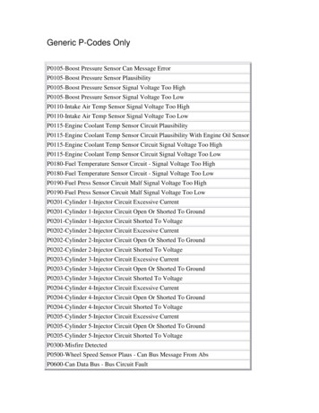
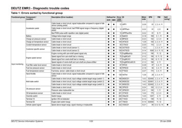
1 IntroductionOne of the most important aspects of planning and operating electrical power systems isthe design of protection systems. Protection systems are designed to detect and removefaults. A fault in an electrical power system is the unintentional conducting path (shortcircuit) or blockage of current (open circuit). The short-circuit fault is typically the mostcommon and is usually implied when most people use the term fault (Grigsby 2001). Wehave limited our discussion to the short-circuit fault variety for this technical report. Afault occurs when one energized electrical component contacts another at a differentvoltage. This allows the impedance between the two electrical components to drop tonear zero allowing current to flow along an undesired path from the one initiallyintended. The short-circuit fault current can be orders of magnitude larger than thenormal operating current (IEEE 2001). The current from such an event can containtremendous destructive energy (heat and magnetic forces), that can damage electricalequipment and pose safety concerns for both utility and non-utility personnel.Common sources of faults on electrical distribution systems include the following (IEEE2008): Insulation breakdown caused by system overvoltages from lighting strikes andswitching surges, improper manufacturing, improper installation, and aged or pollutedinsulation. Mechanical issues such as animal contact, tree contact, vehicle collisions, wind,snow, ice, contamination, vandalism, and major natural disasters. Thermal issues such as overcurrent and overvoltage.Protection engineers are familiar with designing protection systems to safely clear shortcircuit faults from the electric power system. One of the technologies that has beenrecently introduced into the electric power system is Distributed Energy Resources(DER). DER are sources of power located at or near loads and interconnected with theelectrical distribution system. Typically, the individual DER unit ratings are less than10MVA and include fossil-fuel, renewable resources and energy storage technologies(Figure 1). DER are becoming more and more common on distribution systems andpresent many challenges to protection engineers. Adding new sources of energy into theelectric power system will increase the amount of available fault current and thereforeinfluence protective devices that are required on the distribution system. This reportdiscusses issues and provides solutions to address fault current contributions frominverter-based distributed energy resources.1
Figure 1. DER Technologies2
2 Protection and Coordination IssuesThe purpose of the electrical power system is to deliver high-quality, safe, and reliableelectric power to homes, industrial plants, and commercial businesses alike. A typicalelectrical power system is shown in Figure 2. Large generation stations are connectedthrough high-voltage transmission lines to substations. These substations containtransformers that reduce the voltage levels for the subtransmission and distributionsystems. The electrical distribution system (EDS) in particular consists of substationtransformers, three-phase and single-phase distribution circuits, protection and switchingequipment, power factor improvement equipment, distribution transformers, and servicedrops.Protecting the EDS and coordinating the components are of utmost importance to anelectric utility. When adding DER into the EDS, the system impacts must be understood.Figure 2. Typical electric power system single-line diagram2.1 Protective RelayingProtective relays are required on a distribution system in order to cause the quick removalfrom service of any electrical equipment associated with the power system when a shortcircuit fault occurs or when the power system begins operating in abnormal conditions.Protective relays are essentially the brains that determine when the appropriate circuitbreaker tripping action should take place. The mechanical device capable of3
disconnecting the faulty element and physically isolating the electrical power systemfrom short circuit disturbances is called a circuit breaker.Figure 3 describes the protective relaying input and output control procedure. Theprotective relay receives information about the EDS (voltage, current, and frequency)through current and voltage transformers. These transformers transform the measuredvoltage and current value to a more appropriate power level to be utilized by theprotective relay. This information is processed by the protective relay and reacts to anyabnormal conditions detected. Each protective relay needs to be set or programmed forthe desired tripping time (i.e., time delay for relay coordination and system reliabilitypurposes). The decision to trip open or to close the circuit breaker is made by the relaylogic algorithms and must be programmed by a relay engineer.Figure 3. Input and output control of a protective relayTwo basic types of protective relay devices are used in today’s electrical power system. Electromechanical relays were first introduced in the early 1900s. A typicalelectromechanical relay is pictured in Figure 4. Electromechanical relays are eithermagnetic attraction type or induction disc relaying type. Magnetic attraction relaysuse a plunger or hinged armature operation. The magnetic attraction is proportional tothe current flowing through the sensing coil, In most cases, closing the contactinitiates a circuit breaker tripping action. The induction disc relay produces a circularmotion that is propostional to the coil current. Both designs have performed reliablysince their introduction over 100 years ago. Utilities, however, are starting to replaceelectromechanical relays with new microprocessor-based relays.4
Figure 4. Electromechanical relay (Glover/Sarma) Microprocessor relays were first introduced in the 1980. Microprocessor relays bringselectivity, speed, and reliability to protective relaying (a typical microprocessorbased relay is shown in Figure 5). They are also capabile of recording and storinglarge data sets when system disturbances, such as faults, occur. Another importantfeature of microprocessor-type relays is their ability to communicate with utilityoperations personnel. This is typically performed via a Supervisory Control and DataAcquisition (SCADA) system. This feature allows utilitity operators to determine thelocation and type of fault that occurred on the power system without dispatching aspecialist, saving time and often improving reliability.Figure 5. Microprocessor relay2.2 Relay CoordinationRelay coordination involves coordinating studies which utilize time current curves(TCC). These curves describe the time to trip characteristics based on the relay settings.Figure 6 shows a typical TCC. The vertical axis represents the magnitude of the faultcurrent and the horizontal axis represents the time the relay will initiate a trip signal tooperate the circuit breaker. Two important TCC parameters to observe are the minimumpickup time and the instantaneous trip time. The minimum pickup time setting will send atrip signal to the circuit breaker for measured fault current magnitude at or above thisthreshold. The instantaneous setting region will send a signal to the circuit breaker to tripas soon as possible if the measured fault current magnitude is at this threshold. Thecircuit breaker trip time decreases as the amount of fault current increases. It is between5
these two set points that the protection engineer will adjust the shape of the TCC to meetvarious protection coordination objectives.Figure 6. Example of a time current curveFigure 7 shows a small section of a typical electrical distribution single-line diagram.Single-line diagrams are simplified drawings that show the major electrical equipment aswell as relays that are used in the EDS being studied. The diagrams are an essential partof the protection engineer’s tools for understanding the behavior of the EDS and whatrelays are utilized for coordination purposes.6
Figure 7. Typical single-line diagramThe goal of relay coordination is to increase the reliability of the system by isolating thefault current source as fast as possible while maintaining power to the rest of thedistribution system. For example, if a fault occurred on the load side of the downstreamcircuit breaker #1 shown in Figure 7, operators would want to clear that feeder circuit asfast as possible while continuing to supply service to the remainder of the distributionsystem. The upstream distribution circuit breaker #2 would only act as a secondary backup device and initiate a tripping signal if the downstream circuit breakers failed. Once thecircuit breaker receives a trip signal from the relay (which depends upon the circuitbreaker vintage and manufacture type) the typical fault clearing times can be anywherefrom 2 to 9 cycles.2.3 DER Related RelayingThere are considerable differences in the performance under fault conditions among thethree basic types of DER: synchronous machines, induction machines, and inverter-basedsources. These differences are discussed in the remainder of this report with a focus onthe characteristics of inverter-based DER. DER, such as fuel cells, wind turbines, solarphotovoltaics (PV), and microturbines, often require inverters to interface with the utilitygrid (Kramer 2009).7
Currently, inverter-based DER provide minimal contribution to the power balance on allbut a few utility distribution systems (Begovic et al. 2001). However, a significantincrease in DER is expected to come on line in the near future. As the penetration level ofDER increases, the effect of DER may no longer be considered minimal. As DERbecome prevalent in the distribution system, equipment rating capability and coordinationof protection systems merit a closer investigation (Kroposki 2008).The fault contribution from a single, small DER unit is not significant; however, the totalcontributions of many small units may alter the fault current level enough to causeovercurrent protection miscoordination and nuisance fuse operation or hamper faultdetection (General Electric, 2003). A DER system may impact the fault coordination of asystem to the point that relay setting and fuse sizing changes are required. By adding afault source to the system, the overall fault current seen by the relay is reduced, whicheffectively de-sensitizes it (Kroposki 2008; General Electric 2003).The amount of DER on a specific distribution circuit is referred to as the penetrationlevel. Typically this is defined as the rated output power of the DER divided by the peakload of the circuit. Some reports have shown that even at relatively low penetration levels(10%), it may be important to analyze the impact this would have on system operation(Baran and El-Markaby 2005). DER may have a major impact on feeder protection, butthe level at which this would occur depends on how the DER is distributed along thefeeder. Continued research in this area is desired for a complete understanding of whatthis penetration level might be. For DER penetration levels above 10% (DER are heavilydependent on supplying loads), voltage regulation can be a serious issue and may need tobe evaluated as well (General Electric 2003).Higher fault current can also affect recloser (RC) operation. RCs are devices that act verymuch like circuit breakers. However, RCs may be programmed to try and reestablishcircuit connection a few cycles after a fault has occurred. This action is warranted on thedistribution level because most faults are of the single line-to-ground type and typicallyare temporary in nature and often last for only a few cycles. It is possible that the extrafault current from the DER may expose RCs to mechanical and thermal stress that isbeyond their limits. Extra fault current may also impact fuse operation, as it may causethe fuse to clear sooner or later than the protection engineer desired. This may cause RCfuse miscoordination and impact the feeder’s reliability considerably (Baran and ElMarkaby 2005).A unique property of inverter-based DER is the power electronics interface. Powerelectronics have the ability to control fault current contributions from DER systems. Thisadjustability can thereby optimize the system protection coordination issues bycontrolling fault current levels (Tang and Iravani 2005). Typically, inverter-based DERare designed to act as ideal current sources. Therefore, they provide minimal fault currentcontributions and have little effect on overcurrent protection and coordination strategiesfor fuse and circuit breakers (General Electric 2003). However, this might not always betrue with increased DER penetration (10% or more) (General Electric 2003; Baran andEl-Markaby 2005).8
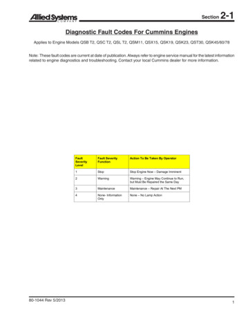
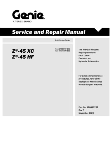
3 Short Circuit AnalysisShort-circuit studies ensure that the wide range of electrical equipment used to generate,transmit, and distribute electrical power is sufficiently sized to interrupt or withstandshort-circuit current. Electrical equipment and protective devices must be properly sizedand set for such events. However, short circuits on the EDS cannot be eliminatedcompletely. Instead, the overall goal is to mitigate and, to a certain extent, contain theirdamaging effects (IEEE 1997). The first goal for short-circuit protection is to clear faultsquickly to prevent fires and explosions and further damage to utility equipment such astransformers and cables (Short 2004). The second goal is to establish practices thatreduce the impact of faults and improve the following. Reliability by properly coordinating protective devices to isolate the smallestpossible portion of the system and affect the fewest customers. Power quality by reducing the duration of voltage sags. Coordination practicesaffect the number and severity of momentary interruptions (Short 2004).There are several types of faults that can occur on the EDS. A 3-phase fault occurs whenall three phases come into contact with each other and is the least common type of fault.A single line-to-ground fault is the most common type of short circuit and occurs whenone phase of the transmitted power comes into contact with alternative current path orground. For example, a tree limb inadvertently falls across a power line. A line-to-linefault occurs when two electrical phases come into contact with each other.The 3-phase fault current typically provides the highest available fault current. However,there are situations where this is not the case. For instance, if a single line-to-ground faultoccurs and there is an effective ground path for current to flow (zero-sequence network),then several current sources could contribute to this fault and exceed the 3-phase faultcurrent. This will depend on how the fault current source or sources are connected to thesystem (i.e. transformer connection delta or wye).Under steady-state operation, the power generated by the source is equal to the powerbeing consumed by the load. The load impedance is the principal determinant of thecurrent magnitude (IEEE 2001). When an additional load (e.g. air conditioner) is turnedon, the total load impedance is reduced, resulting in an increase in current flowing in thearmature winding of the rotating machine. This increase in current will cause themachine’s rotor to actually slow down due to the armature reactance. Due to thisincreased load demand, the frequency of the power system will deviate slightly lower. Inorder to maintain constant frequency (60 Hz in the United States) the generator turbinemust respond with additional torque (prime mover) to match this new power demand.A fault in a typical EDS behaves very much like a resistive-inductive (RL) circuit (seeFigure 8) with the switch in the closed position. Closing the switch simulates a faultedcondition. Bypassing the predominantly resistive load, an extremely low impedance path(a large load has been added to the circuit) has been created to ground, causing thegenerator to supply a higher level of current. The fault current is limited by the machine’sinternal impedance and the transmission impedance path (R jXL).9
Figure 8. Circuit model for asymmetrical fault currentIn order to explain the fault current behavior of such an event, we need solve for thecurrent when the switch is closed (see Figure 8). Writing a Kirchhoff’s Voltage Law(KVL) equation around the circuit we get Equation 1.VS Ri Ldidt(1)Where R is circuit resistance, i is the current, and L is the circuit inductance. Theinductance L can be determined usingXL ω L(2)where, ω is angular frequency. Solving the differential equation for the symmetrical oralternating-current (AC) steady-state fault current we get Equation 3.iac t ( )VS(1 e T )R(3)T L X R ωR(4)where,10
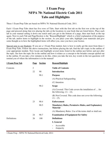
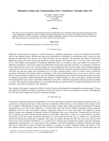
Figure 9. AC symmetrical short-circuit currentFigure 9 shows the AC symmetrical fault current for a synchronous generator. The ACsymmetrical fault current is characterized by the magnetic flux trapped in the statorwindings (mostly inductance) of the rotating machine and cannot change instantaneously.This is why synchronous machines under fault conditions feature different flux variationpatterns compared to induction machines. The flux dynamics dictate that the fault currentdecays with time until a steady-state value is reached.Equation 3 describes the temporary direct-current (DC) offset fault current.idc I 0 etT ( )(5)Equations 4 and 5 describe the time constant (how fast it will decay) and the reactance asthe product of the angular frequency and the inductance. A detailed solution can be foundin, IEEE Red Book, Std 141-1993.11
Figure 10. Decaying DC offset short-circuit currentThe DC fault component is characterized by the fact that inductors and capacitors
abnormal conditions detected. Each protective relay needs to be set or programmed for the desired tripping time (i.e., time delay for relay coordination and system reliability purposes). The decision to trip open or to close the circuit breaker is made by the relay logic algorithms and