Transcription
Distribution Automation HandbookSection 8.2 Relay Coordination
Distribution Automation Handbook (prototype)1MRS757285Power System Protection, 8.2 Relay Coordination2Contents8.2 Relay Coordination and Selective Protection . 38.2.1Introduction . 38.2.2Time-graded Protection . 38.2.3Time- and Current-graded Protection . 118.2.4Time- and direction-graded protection . 128.2.5Current- and Impedance-graded Protection . 158.2.6Interlocking-based Protection . 178.2.7Differential Protection . 198.2.7.18.2.7.2LOW-IMPEDANCE PRINCIPLE . 20HIGH-IMPEDANCE PRINCIPLE . 22
Distribution Automation Handbook (prototype)1MRS757285Power System Protection, 8.2 Relay Coordination38.2Relay Coordination and Selective Protection8.2.1IntroductionThe selected protection principle affects the operating speed of the protection, which has a significant impact on the harm caused by short circuits. The faster the protection operates, the smaller the resulting hazards, damage and the thermal stress will be. Further, the duration of the voltage dip caused by the shortcircuit fault will be shorter, the faster the protection operates. Thus, the disadvantage to other parts of thenetwork due to undervoltage will be reduced to a minimum. The fast operation of the protection also reduces post-fault load peaks which, in combination with the voltage dip, increase the risk of the disturbancespreading into healthy parts of the network. In transmission networks, any increase of the operation speedof the protection will allow the loading of the lines to be increased without increasing the risk of losing thenetwork stability.Good and reliable selectivity of the protection is essential in order to limit the supply interruption to thesmallest area possible and to give a clear indication of the faulted part of the network. This makes it possible to direct the corrective action to the faulty part of the network and the supply to be restored as rapidly aspossible.Thus, attention must be paid to the operating speed of the protection, which can be affected by a proper selection of the applied protection principle. Selective short-circuit protection can be achieved in differentways, such as: Time-graded protection Time- and current-graded protection Time- and direction-graded protection Current- and impedance-graded protection Interlocking protection Differential protection8.2.2Time-graded ProtectionA straightforward way of obtaining selective protection is to use time grading. The principle is to grade theoperating times of the relays in such a way that the relay closest to the fault spot operates first. Time-gradedprotection is implemented using overcurrent relays with either definite time characteristic or inverse timecharacteristic. The operating time of definite time relays does not depend on the magnitude of the fault current, while the operating time of inverse time relays is shorter the higher the fault current magnitude is. Thetime-graded protection is best suited for radial networks.The principle of inverse time protection is especially suited for radial networks where the variations ofshort-circuit power due to changes in network configuration are small or where the short-circuit currentmagnitude at the beginning and end of the feeder differs considerably. In these cases, the use of inversetime relays in favor of definite time relays can usually speed up the operating time of the protection at high
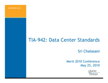
Distribution Automation Handbook (prototype)1MRS757285Power System Protection, 8.2 Relay Coordination4fault current magnitudes. Time grading with fuses is also easier to obtain with inverse time relays. Considering the above arguments and also taking into account, for example the short-circuit current withstandcapacity of the network components, applying inverse time relays for the network short-circuit protectionmay be justified.The IEC 60255-151 and BS 142 standards define four characteristic time-current curve sets for inverse timerelays: Normal inverse Long-time inverse Very inverse Extremely inverseFor inverse time relays the operating time (s) can be calculated from the equation:t k βα I 1 I (8.2.1)wherekis an adjustable time multiplierIis the measured phase current valueis the set start (pickup) current valueare curve set-related parametersI α, βAccording to the standards, the relay should start once the energizing current exceeds 1.3 times the set startcurrent when the normal, very or extremely inverse time characteristic is used. When the long-time inversecharacteristic is used the relay should start when the energizing current exceeds 1.1 times the set start current.The parameters α and β define the steepness of the time-current curves as follows:Table 8.2.1: Curve set related parametersαβNormal inverse0.020.14Very inverse1.013.5Extremely inverse2.080.0Long-time inverse1.0120.0Type of characteristicFigure 8.2.1 shows a time-graded protection arrangement in a radial network. In the example network,three-stage protection is implemented. For the low-set stage (3I ), either inverse time or definite time characteristic can be given. The high-set and the instantaneous stage (3I and 3I ) have definite time cha-
Distribution Automation Handbook (prototype)1MRS757285Power System Protection, 8.2 Relay Coordination5racteristic and their purpose is to accelerate the operation of the protection under heavy fault current conditions. A multiple-stage protection is often required to meet with the sensitivity and operating speed requirements and to achieve a good and reliable grading of the protection, see Figure 8.2.1.Studying and planning of time-selective protection schemes is most conveniently carried out using selectivity diagrams. The selectivity diagram is a set of specific time/current curves which shows all thetime/current curves, that is, the operating characteristics of the relays of the concerned chain of protectionrelays. The chain of relays in the example of Figure 8.2.1 includes two relays. The selectivity diagram alsoincludes additional information needed for the planning and operation of the protection, such as the lowestand highest fault current levels in the relaying points, maximum load current, nominal currents and shortcircuit current withstand capacity of network components and the maximum limit values of possibleswitching inrush currents and start currents.The selectivity diagram of Figure 8.2.1 shows that should a fault arise, for example, in the far end of thefeeder (outgoing feeder 1) protected by relay 1, the fault current magnitude will be on the level indicated by . This fault causes both the relay 1 and relay 2 to start (outgoing feeder 1). Thus, the concerned feeder belongs to the protection area of the relay 1 and relay 2, providing an inherent backup protection for the feeder. Should relay 1 or its circuit breaker fail to operate, relay 2 will be allowed to operate.time (s)10 112243I 35Δt IDMT10 03I ΣI L3I 610 -1I KmaxI KminΔt DTFEEDER 120 kVINCOMER3I MF12 11810 910 210 376 OPERATING CHARACTERISTICS OF O/C PROTECTION, FEEDER 12 OPERATING CHARACTERISTICS OF O/C PROTECTION, INCOMER 13 INRUSH CURRENT PEAK VALUE, FEEDER 14 , 5MF3I 10 4current (A)11linetype 27I KmaxI Kminlinetype 13I 0ΣI LI THERMAL WITHSTAND, LINE TYPE 1 AND 289 INCOMER RATED CURRENT10 LINE TYPE 2 RATED CURRENTI KmaxI Kmin11 LINE TYPE 1 RATED CURRENT12 HIGHEST LOAD CURRENT, FEEDER 1Figure 8.2.1:Overcurrent protection of radial network and the corresponding selectivity diagramThe selection of the proper grading time is of essential importance for the selectivity of the protection. Thegrading time is the time difference between two consecutive protection stages. In heavy fault current conditions, the relay operating time must not be unnecessarily prolonged and, on the other hand, a satisfactory
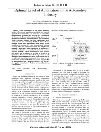
Distribution Automation Handbook (prototype)1MRS757285Power System Protection, 8.2 Relay Coordination6margin must be maintained to secure the selectivity. When inverse time relays are used instead of definitetime relays, longer grading times must generally be used, because, among other things, the effect of the inaccuracy of the current measurement on the operating time must be observed.In the example of Figure 8.2.1, the grading times have been defined separately for each stage. The gradingtime between the inverse time stages have been denoted Δt IDMT and, correspondingly, the grading time between definite time stages has been denoted Δt DT . When defining the grading time, it must be noted that atlower fault current levels the prevailing load currents ΣI L of the healthy feeders during the fault must betaken into account to a certain degree. These currents are summed, for example, into the current measuredby relay 2 when a fault appears on feeder 1.When numerical relays are used, the required grading times can be calculated from Equations (8.2.2) and(8.2.3). Figure 8.2.2 shows how the grading times and the factors affecting them are formed. For definitetime relays, the grading time Δt DT is obtained from Equation (8.2.2).Δt DT 2 t E t R tCB t M(8.2.2)wheretEis the tolerance of the relay operating timetCBis the circuit breaker operating timetRis the relay retardation timetMis the safety marginThe safety margin takes into account the possible delay of the relay operation due to CT-saturation causedby the DC-component of the fault current. The length of the possible additional delay thus occurring is affected by the fault type, fault current magnitude and the ratio between the CT-accuracy limit factor and theset current value. In theory, the delay can even be as long as the time constant of the DC-component,should the fault current just slightly exceed the set value and should the set value have been chosen justslightly below the corresponding CT-accuracy limit factor. In practice, however, the CTs of the consecutiverelays of the protection chain will saturate within a certain fault current range, which means that the operation of the relays is about equally delayed. For this reason, a safety margin of about the length of the fundamental frequency cycle is enough.If, however, relatively big differences in the accuracy limit factors of successive CTs in the protection chainexist, it might be justifiable to increase the safety margin in relation to the time constant of the DCcomponent. The safety margin is also to be increased if auxiliary relays are used in the trip circuit of thecircuit breaker.The retardation time is the time period just before the elapsing of the operation delay timer. If the fault disappears before the starting of the retardation time, the protection relay that has been started by the fault isstill able to cancel its tripping command. If the fault disappears during the retardation time just before theelapsing of the operation delay timer, the tripping command will be initiated.
Distribution Automation Handbook (prototype)1MRS757285Power System Protection, 8.2 Relay Coordination7The grading time Δt IDMT for protection schemes based on inverse time relays is obtained from Equation(8.2.3): 1 E1 100 Δt IDMT t1 1 t R t CB t M 1 E 2 100 (8.2.3)wheretCBis a factor which takes into account the superimposed effect of the operating time error caused by the inaccuracy of the current measurementand the operating time tolerance in the relay located closest to the faultspot (%) 1)is a factor which takes into account the superimposed effect of the operating time error caused by the inaccuracy of the current measurementand the operating time tolerance in the relay located next in the protection chain (%) 1)is the circuit breaker operating timetRis the retardation timetMis the safety margint1is the calculated operating time of the relay closest to the fault spot 1)E1E2time1) Corresponds to the current value with which the grading time is determined, Figure 8.2.2.23I 213I FEEDER 120 kVE 2 (%)INCOMERE 1 (%)MF1t1MFt2t CB t RΔt IDMT3I t CB t R3I ΣI LΣI LI1Figure 8.2.2:tEtEΔt DTcurrentI2I KmaxGrading time determination and factors affecting it. Notations: I 1 , I 2 current values with which the grading time between the low-set stages (3I ) is determined, I kmax maximum short-circuit current. For other notations, see Equations (8.2.2) and(8.2.3).
Distribution Automation Handbook (prototype)1MRS757285Power System Protection, 8.2 Relay Coordination8The tolerance values of the operating times are standardized, Table 8.2.2:Table 8.2.2: Limit values, according to the BS 142 standard, of the operating times expressed as apercentage. E accuracy class indexI/I Normal inverseVery inverseExtremely inverseLong time 201.00·E1.00·E1.00·E-Furthermore, the effect of the current measuring inaccuracy on the operating time of the inverse time protection must be observed. The effect can be evaluated using Equation (8.2.1) by giving values to the phasecurrent according to the measuring inaccuracy used. The measuring inaccuracy is affected not only by therelay type but also by the accuracy of the measurement transformers. By adding the percentage of the operating time inaccuracies thus obtained to the values of Table 8.2.2 , the values of the factors E1 and E 2 canbe found.
Distribution Automation Handbook (prototype)1MRS757285Power System Protection, 8.2 Relay Coordination9Example of the determination of the grading time Δt DTThe grading time between the high-set stages of the numerical protection relays inFigure 8.2.1 is determined using the Equation (8.2.2): 2 times the tolerance of the operating time:2 x 25 ms Circuit breaker operating time:50 ms Retardation time:30 ms Safety margin:20 ms Total:150 msThe safety margin has been given the smallest possible value, and so the grading time Δt DT 150 ms can bechosen, see Figure 8.2.1.Example of the determination of the grading time Δt IDMTThe grading time between the low-set stages of the numerical protection relays in Figure 8.2.1 is determined using Equation (8.2.3):Current values with which the grading time is determined: Relay 1: I1 1200 A 4.0 times the current setting of the stage Relay 2: I 2 1700 A 2.4 times the current setting of the stageThe selected curve type is normal inverse and the accuracy class E which equals 5%.Table 8.2.2 is used and the operating time tolerances are selected to correspond to the currents I1 and I 2mentioned above. Table 8.2.2 shows that tolerances closest to those currents are 1.13·E (relay 1) or 6% and2.22·E (relay 2) or about 11%.The effect of the current measuring inaccuracy on the operating times in per cent from the calculated operating times t1 and t 2 is determined using Equation (8.2.1), and when the joint current measuring inaccuracyof the relay and the measurement transformer is expected to be 3%, Table 8.2.3 and Table 8.2.4. It mustalso be noted that the operating time error thus arising is independent of the setting of the time multiplier kof the inverse time curve.Table 8.2.3: The effect of the current measuring inaccuracy on the operating times in relation to thecalculated operating times t 1 of relay 1 for the current I 1I1(x I )Current measurementerror(%)4.04.0 3-3Operating time error(t - t 1) / t 1 x 100(%)-2 2
Distribution Automation Handbook (prototype)1MRS757285Power System Protection, 8.2 Relay Coordination10Table 8.2.4: The effect of the current measuring inaccuracy on the operating times in relation to thecalculated operating times t 2 of relay 2 for the current I 2I2(x I )Current measurementerror(%)2.42.4 3-3Operating time error(t - t 2) / t 2 x 100(%)-3 3The factors E1 and E 2 are calculated as the sum of the absolute values of the errors: Relay 1: E1 8% Relay 2: E 2 14%By inserting factors E1 and E 2 into Equation (8.2.3) and by observing that the calculated operating time t1of relay 1 is 1000 ms at 1200 A (4 x the set current), the required grading time can be calculated as follows: 1 E1 100 t1 1 : 1 E 2 100 260 ms CB-operating time:50 ms Retardation time:30 ms Safety margin:20 ms Total:360 msAccording to this, the grading time Δt IDMT should be given a value of at least 360 ms, Figure 8.2.1.The time-graded protection can also be implemented with definite time underimpedance relays. The relaymeasures the phase currents and phase-to-phase or phase-to-earth voltages. Based on these values, it determines the apparent impedance seen from the relay location. The relay operates if the measured impedancefalls below the set start value. The set start value determines the so-called reach of the relay, which definesat which distance faults seen from the relaying point can still be detected. Owing to the measuring principle, the advantage of the impedance relay is that its operation is independent of the short-circuit power ofthe incoming network. The reach and the operating time of the relay are unchanged even if the source impedance changes, for example, when the network configuration is altered. Thus the relay operates reliablyeven though the short-circuit current would be particularly low. For this reason, underimpedance relays arefrequently used as feeder protection relays in networks with low short-circuit power. Another typical application is the use of underimpedance relays as backup protection relays in vicinity of power plants where thefault current may decay under the set start value of overcurrent relays due to the effect of generators. If theprotection of the outgoing lines from the power plant is also based on the impedance-measuring principle,selectivity between the relays can be easily obtained. The aforementioned salient principles of time gradingalso apply to underimpedance protection.
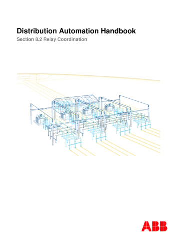
Distribution Automation Handbook (prototype)1MRS757285Power System Protection, 8.2 Relay Coordination118.2.3Time- and Current-graded ProtectionTime- and current-graded protection can be used in cases where the fault current magnitudes in faults occurring in front of and behind the relaying point are different. Due to the different fault current levels usinginverse time relays but also multi-stage definite time relays, different operating times can be obtained in either direction. In this way the requested time grading can be obtained and the operating time requirementscan be fulfilled.Figure 8.2.3 shows an example time- and current-graded overcurrent protection application. The study ofthe time grading towards one particular generator feeder is straightforward if the operating characteristic ofthe protection of the other generator feeders are combined in a single operating characteristic of a so-calledequivalent generator feeder. This is obtained by multiplying the current values of the relay operating characteristic of a single generator by the number of generators in use at any time, operating characteristic 3G ,Figure 8.2.3. From the selectivity diagram, it can be seen that when a fault occurs on feeder 4, for example,the total fault current fed by the network and the other feeders reaches the level indicated by . Thus, theoperating time of the protection can even be shorter than 100 ms. The fault current fed by the equivalentgenerator is at least on the level indicated by . It can clearly be seen that in this way a reliable timegrading is obtained between the generator feeders also in cases where the fault current fed by the network isparticularly low or if one generator is out of operation. The same method of study can be applied for planning the time-grading between the protection relays of the block transformer and the generator feeders forfaults occurring in the network side. In this planning, special attention must be paid to the number of generators in operation and its effect on the the selectivity. Should machines be taken out of operation, the timegrading towards the network can be endangered if the settings of the protection relays of the block transformer are not adapted to the operating conditions at any time.The protection practice described can also be used in the overcurrent protection of ring and meshed networks. Another area of application is the earth fault protection of effectively earthed ring and meshed networks.
1MRS757285Power System Protection, 8.2 Relay Coordination12time (s)Distribution Automation Handbook (prototype)10 1NETWORK31G3G13IKGEN.FEEDER 110 0GEN.FEEDER 2GEN.FEEDER 3GEN.FEEDER 4BLOCKTRAFOMFMFMFMF1G10 -13I 11IK21123435 6 7 8 9 101IKIKIK42030current (I / Ing ) GENERATOR THERMAL WITHSTAND (IEC 34-1) 3G1G OPERATING CHARACTERISTICS, GENERATOR FEEDER143I 3G OPERATING CHARACTERISTICS, EQUIVALENT GENERATOR(3 GENERATORS )3Figure 8.2.3:8.2.4 EQUIVALENT GENERATOR THERMAL WITHSTAND (IEC 34-1)(3 GENERATORS)1 FAULT CURRENT SUPPLIED BY ONE GENERATOR2 FAULT CURRENT SUPPLIED BY EQUIVALENT GENERATOR(3 GENERATORS)3 FAULT CURRENT SUPPLIED BY EXTERNAL NETWORK4 TOTAL FAULT CURRENT SUPPLIED BY EXTERNAL NETWORK AND EQUIVALENT GENERATORPower plant overcurrent protection implemented with time and current grading towards the generator feeders. The generators are of equal rated power and their inverse time relays share the same settings. I ng rated current of a single generator.Time- and direction-graded protectionIn ring and meshed networks, the selectivity of the protection can be based on directional overcurrent relays. Directional relays are needed as different operating times are required depending on the location of thefault, that is, if the fault spot is in front of the relaying point on the feeder or behind the relaying point, forexample, on the incoming feeder or on the busbar system.The directional overcurrent relay operates once the fault current exceeds the set start current and the direction of the fault current complies with the setting. Thus the selectivity of the protection is based on bothtime and current direction. The directional overcurrent protection can operate either according to definitetime or inverse time characteristics and the aforementioned central principles of time-grading are also applicable to directional protection.Typical applications based on directional protection are shown in Figure 8.2.4.
Distribution Automation Handbook (prototype)1MRS757285Power System Protection, 8.2 Relay Coordination133I 3I 3I 3I 3I 3I 3I 3I 3I 3I 3I 3I 3I 3I 3I Figure 8.2.4:3I 3I 3I 3I 3I 3I 3I 3I 3I 3I 3I 3I 3I 3I 3I Directional overcurrent relays applied to short-circuit protection of ring-type networks supplied from one pointVarious principles are used for determining the direction of the fault current. The most conventional way isto determine the direction phase-specifically so that the current phasor of each faulty phase is compared tothe phasor of the opposite phase-to-phase voltage, for example, the direction of the phase current phasorI L1 is compared to the direction of the phasor U 23 . The relay operates if one or more of the direction comparisons show that the fault is located in the forward or reverse direction with regard to the set relay operating direction. An example operating characteristic formed in this way is shown in Figure 8.2.5.
Distribution Automation Handbook (prototype)1MRS757285Power System Protection, 8.2 Relay Coordination14U12-90 180 U12UL1UL1 90 IL1REVERSEϕ 180 U23U23current settingUL2current settingU31 90 Phase L1:UL3FORWARDϕUL2-90 UL3Figure 8.2.5:REVERSEFORWARDIL2U31Phase L2:Direction determination principle of phases L1 and L2 based on using the oppositephase-to-phase voltage U L 23 and U L 31 correspondingly. The fault is located in forward direction.Another way of determining the direction is first to indentify the faulty phases on the basis of the starts ofthe phase-specific overcurrent functions and then compare the difference between these current phasors tothe difference between the other two phase-to-phase voltages, for example, the direction of the phasorI L1 I L 2 is compared to the direction of the phasor U 23 U 31 . Alternatively, the phasor I L1 I L 2 can alsobe compared to the direction of the corresponding faulty phase-to-phase phasor U 12 , or to the corresponding positive-sequence voltage U 1 ,which must be suitably rotated according to the fault type in question.The said direction determination methods need to be supported by a voltage memory which stores the phasors of the pre-fault voltages. The relay uses the stored information for determination of the fault current direction in cases where the voltages are too low to be measured, that is, close-in short circuits. The advantage of the methods not using the corresponding faulty voltage is that the voltage memory is needed only inthree-phase close-in short circuits. In two-phase short circuits, the voltages needed for the determination ofthe direction are always high enough to be measured. If using the faulty voltage in direction determination,the voltage memory is needed also in two-phase close-in short circuits. However, the advantage of this method is that the phase order of the power system has no impact on the direction determination.The protection of ring and meshed networks can also be carried out using directional definite time underimpedance or distance relays. These relays are frequently used for the protection of transmission and subtransmission networks, meshed or ring-operated distribution networks or weak radial networks. The advantages of the use of distance relays are the same as for the underimpedance relays in general, and the generaltime-grading principles also apply in this protection concept. To achieve a good and reliable selectivity andto fulfill the operating speed requirements as well as possible, it is typically necessary to implement multiple directional underimpedance stages. The reach of these stages defines the zones of protection towardthe desired operating direction, which can be either forward of reverse. An example of this can be seen inFigure 8.2.6, where multiple-stage numerical distance relay units are applied to the short-circuit protectionof a sub-transmission network. The figure also shows the principal reaches of the different zones of the ex-
Distribution Automation Handbook (prototype)1MRS757285Power System Protection, 8.2 Relay Coordination15ample relay unit. The zones Z1, Z2 and Z3 are set in the forward direction, that is, toward the protected lineand the zone Z4 in the reverse direction.The zone Z1 is underreaching the remote end station, making it possible to apply minimum operating times.Zone Z2 is slightly overreaching the remote end, which means that the time coordination with zone Z1 ofthe successive line is required; therefore the operating time is delayed as much as the grading margin requires. Zone Z3 operates as an overreaching backup protection and the operating time must be selected sothat it coordinates with the protection in the forward direction in all conditions. Zone Z4 operates as anoverreaching backup protection in the reverse direction, and the reach of this zone is selected so that it candetect faults even on the MV-side of the transformers. The operating time is selected accordingly. The mainpurpose of the zone Z4 is to operate as a backup protection for the transformers. The main advantage of using distance relays in this example is that all faults occurring in the sub-transmission network can becleared by the zones Z1 or Z2 in less than 0.2 seconds. Also possible fault current infeed from the distribution network side due to distributed generation, for example, does not affect the selectivity of the kMV-networkMV-networkFigure 8.2.6:8.2.5MV-networkThe application principle of numerical multiple-stage distance protection for shortcircuit protection of a sub-transmission ring main system. MV distribution voltage.The notation 1 //- or 2 // transformer indicates the number of parallel transformersfeeding the distribution network at any given timeCurrent- and Impedance-graded ProtectionIn certain cases, protection principle based on current and impedance grading can be used to essentiallyaccelerate the operation of the protection in faults arising close to the relaying point. The protection is implemented by using one directional or non-directional stage of the overcurrent or underimpedance relay.
Distribution Automation Handbook (prototype)1MRS757285Power System Protection, 8.2 Relay Coordination16The intention is to set the start current of the overcurrent stage so high that when a fault arises in front ofthe next relay in the protection chain, the concerned stage will not operate and no time-grading is needed.Correspondingly, when an underimpedance stage is used, the reach should be set low enough to obtain thecorresponding function. For example, in Figure 8.2.6 the zone Z1 operates according to this principle.In accordance with the principle
The safety margin takes into account the possible delay of the relay operation due to CT-saturation caused by the DC-component of the fault current. The length of the possible additional delay thus occurring is af-fected by the fault type, fault current magnitude and the ratio between the CT