Transcription
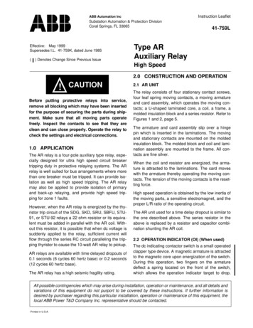
Instruction LeafletABB Automation IncSubstation Automation & Protection DivisionCoral Springs, FL 33065Effective: May 1999Supersedes I.L. 41-759K, dated June 1985() Denotes Change Since Previous Issue41-759LType ARAuxiliary RelayHigh Speed2.0 CONSTRUCTION AND OPERATION! CAUTIONBefore putting protective relays into service,remove all blocking which may have been insertedfor the purpose of securing the parts during shipment. Make sure that all moving parts operatefreely. Inspect the contacts to see that they areclean and can close properly. Operate the relay tocheck the settings and electrical connections.1.0 APPLICATIONThe AR relay is a four-pole auxiliary type relay, especially designed for ultra high speed circuit breakertripping duty in protective relaying systems. The ARrelay is well suited for bus arrangements where morethan one breaker must be tripped. It can provide isolation as well as high speed tripping. The AR relaymay also be applied to provide isolation of primaryand back-up relaying, and provide high speed tripping for zone 1 faults.However, when the AR relay is energized by the thyristor trip circuit of the SDG, SKD, SRU, SBFU, STU91, or STU-92 relays a 22 ohm resistor or its equivalent must be added in parallel with the AR coil. Without this resistor, it is possible that when dc voltage issuddenly applied to the relay, sufficient current willflow through the series RC circuit paralleling the tripping thyristor to cause the 10-watt AR relay to pickup.AR relays are available with time delayed dropouts of0.1 seconds (6 cycles 60 hertz base) or 0.2 seconds(12 cycles 60 hertz base).The AR relay has a high seismic fragility rating.2.1 AR UNITThe relay consists of four stationary contact screws,four leaf spring moving contacts, a moving armatureand card assembly, which operates the moving contacts; a U-shaped laminated core, a coil, a frame, amolded insulation block and a series resistor. Refer toFigures 1 and 2, page 5.The armature and card assembly slip over a hingepin which is inserted in the laminations. The movingand stationary contacts are mounted on the moldedinsulation block. The molded block and coil and lamination assembly are mounted to the frame. All contacts are fine silver.When the coil and resistor are energized, the armature is attracted to the laminations. The card moveswith the armature thereby operating the moving contacts. The tension of the moving contacts is the resetting force.High speed operation is obtained by the low inertia ofthe moving parts, a sensitive electromagnet, and theproper L/R ratio of the operating circuit.The AR unit used for a time delay dropout is similar tothe one described above. The series resistor in theabove is replaced by a resistor and capacitor combination shunting the AR coil.2.2 OPERATION INDICATOR (OI) (When used)The dc indicating contactor switch is a small operatedclapper type device. A magnetic armature is attractedto the magnetic core upon energization of the switch.During this operation, two fingers on the armaturedeflect a spring located on the front of the switch,which allows the operation indicator target to drop.All possible contingencies which may arise during installation, operation or maintenance, and all details andvariations of this equipment do not purport to be covered by these instructions. If further information isdesired by purchaser regarding this particular installation, operation or maintenance of this equipment, thelocal ABB Power T&D Company Inc. representative should be contacted.Printed in U.S.A.
41-759LAR High Speed Auxiliary RelayThe target is reset from the outside of the case by apush-rod located at the bottom of the cover.Table 1:Operate and Reset TimesThe front spring, in addition to holding the target, provides restraint for the armature and thus controls thepickup value of the switch.RatedOperating3.0 CHARACTERISTICS†The AR unit without a series resistor has a sensitivityof 500 milliwatts. By the proper combination of theAR unit and a series resistor, an optimum speed of 2milliseconds can be obtained for an energy input of10 watts.ResetTime(Milliseconds)Operate ntactOpens102.252.03.51.52.5†Typical operating times and effective contact bounceare outlined in the Tables 1 and 2.4.03.52.25 W AR is a different style than the 10W ARTable 2:Contact BounceAll relays are capable of being energized continuously. All high speed relays will pick up at 80% ofrated voltage or less; and drop out at 5% of ratedvoltage or higher.Effective BounceTime inMillisecondsRelays with delayed dropout are available with a minimum dropout time of 0.1 second and also availablewith a minimum dropout time of 0.2 seconds.ContactLoadingNormallyOpenDry Circuit10 Watt (One AR Relay)Breaker Trip Coil3.1 CONTACT RATING (Table 3)Each relay contact is rated 3 amps continuous and30 amps long enough to trip a breaker.21.2Table 3:Contact RatingInterrupting Rating 000.250Double20.01.70.5Carry Rating (Amps)InductiveL/R 1.7500.3500.15020.01.20.250333NormallyClosed6-8---
41-759LAR High Speed Auxiliary Relay4.0 SETTINGSContact Pressure4.2 OPERATION INDICATORS (OI)a. On four normally open contact relays, thenormally open contacts should have approximately 4 grams pressure on the card in thede-energized position, and 15 to 30 gramscontact pressure in the energized position.The only setting required on the OI is the selection ofthe 0.2 or 2.0 ampere tap setting. This selection ismade by connecting the lead located in front of thetap block to the desired setting by means of the connecting screw.b. On relays with two normally open and twonormally closed contacts, the normallyclosed contacts should have approximately 15 grams contact pressure in thede-energized position.4.1 AR UNITNo settings are required.5.0 INSTALLATIONThe relays should be mounted on switchboard panels or their equivalent in a location free from dirt,moisture, excessive vibration, and heat. Mount therelay vertically by means of the four mounting holeson the flange for a semi-flush mounting or by meansof the rear mountings stud or studs for projectionmounting. Either a mounting stud or the mountingscrews may be utilized for grounding the relay. Theelectrical connections may be made directly to theterminals by means of screws for steel panel mounting or to the terminal studs furnished with the relayfor thick panel mounting. The terminal studs may beeasily removed or inserted by locking two nuts on thestud and then turning the proper nut with a wrench.For detailed FT case information refer to I.L. 41-076.6.0 ADJUSTMENTS ANDMAINTENANCEThe proper adjustments to insure correct operation ofthis relay have been made at the factory and shouldnot require readjustment after receipt by the customer. If the adjustments have been changed or therelay taken apart for repairs, the calibration instructions below should be followed.6.1 ACCEPTANCE CHECKThe following check is recommended to insure thatthe relay is in proper working order.Contact Gapsa. Normally open contacts should have a gapof .018 to .023 inch.b. Normally closed contact gap should be .013minimum.Each normally open contact spring shouldhave approximately 8 grams pressureagainst the card.NOTE:For this check to be made accurately, it is necessary toback out the NC stationary contact screw. This will disturb the factory calibration and therefore it is recommended this check not bemade on a relay which passes all other checks.Armature GapThe armature gap should be approximately .009inches measured at the narrowest part of the armature gap.Contact Operate TimePer Table 1.Operation Indicator (OI)Close the main relay contacts and pass sufficient dccurrent through the circuit to drop the OI. This valueof current should be not greater than the particular OItap setting being used. The operation indicator targetshould drop freely.6.2 SPECIAL AR RELAY WITH TIME DELAYDROPOUTConnect the relay as shown in Figure 16 page 12.When the AR coil has been energized for 25-35 milliseconds its dropout time should be a minimum of100 milliseconds. The AR relay should be adjustedsuch that its contact break time is 25-35 milliseconds.Also the timer should be of the type which may bestarted and stopped by break contacts.6.3 AR RELAYS WITH TIME DELAY DROPOUTConnect the relay as shown in Figure 17 page 13.When the AR coil has been energized approximately3 cycles, (40 millisecond or longer) the dropout time3
41-759LAR High Speed Auxiliary Relayshould be a minimum of 100 milliseconds or thedropout time should be a minimum of 200 milliseconds depending upon the relay style.open contact spring for 8 grams to just movethe contact away from the card. Adjust thenormally closed contact for 15 grams springpressure, to just move contact spring awayfrom the card. Then adjust the stationarycontact to just move the contact spring awayfrom the card. For this check to be madeaccurately, it is necessary to back out theNC stationary contact screw. This willdisturb the factory calibration and therefore it is recommended this check not bemade on a relay which passes all otherchecks.7.0 CALIBRATIONUse the following procedure for calibrating the relay ifthe relay has been taken apart for repairs or theadjustments disturbed. This procedure should not beused until it is apparent that the relay is not in properworking order. (See “Acceptance Check”, page 3)7.1 TRIPPING RELAY (AR)The type AR tripping relay unit has been properlyadjusted at the factory to insure correct operation,and under normal field conditions should not requirereadjustment. If, however, the adjustments are disturbed in error, or it becomes necessary to replacesome part, use the following adjustment procedure.This procedure should not be used until it is apparentthat the relay is not in proper working order.a. Adjust the set screw at the rear of the top ofthe frame to obtain a 0.009-inch gap at therear end of the armature air gap.b. On the four normally open contact relayadjust each contact spring to obtain 4 gramspressure at the very end of the spring. Thispressure should be sufficient to move thespring away from the edge of the slot of thecard.On the two normally open two normallyclosed contact relay, adjust each normally4c.Adjust each normally open stationary contactscrew to obtain a contact gap of 0.020 to0.022 inches. Energize the relay and the normally open contacts should have 15 to 30grams contact pressure. The normallyclosed, if any, should have a contact gap of.015 inches.When calibrated as outlined above, the relayshould meet the characteristics of Tables 1 and 2.8.0 RENEWAL PARTSRepair work can be done most satisfactorily at thefactory. However, interchangeable parts can be furnished to the customers who are equipped for doingrepair work. When ordering parts, always give thecomplete nameplate data.
53.4.5.6.6Leaf spring moving contactsMoving card assemblyRelay coilMolded isolation block4Figure 1. Type AR Unit with 2 Make – 2 Break Contacts (Front View).1. Normally closed stationarycontact screws2. Normally open stationarycontact screws231stationarystationary644. U-shaped laminated core5. Armature gap adjustment setscrew6. Armature Gap5Figure 2. Type AR Unit with 2 Make – 2 Break Contacts (Side View).1. Normally closedcontact screws2. Normally opencontact screws3. Moving Armature231AR High Speed Auxiliary Relay41-759L5
6Figure 3. Internal Schematic of the Type AR Relay with 4 Make Contacts inFT-11 Case.Sub 4629A496Figure 4. Internal Schematic of the Type AR Relay with 2 Make – 2 BreakContacts in FT-11 Case.Sub 2837A11341-759LAR High Speed Auxiliary Relay
Figure 5. Internal Schematic of the Type AR Relay in FT-22 Case, Double Unit,with 8 Make Contacts.*Sub 5629A495Figure 6. Internal Schematic of the Type AR Relay in Ft-22 Case, Double Unit,with 6 Make – 2 Break Contacts.Sub 2762A529AR High Speed Auxiliary Relay41-759L7
8Figure 7. Internal Schematic of the Type AR Relay in Ft-22 Case, Double Unit,with 4 Make – 4 Break Contacts.*Sub 4762A580Figure 8. Internal Schematic of the Type AR Relay in Front Connected MoldedCase with 4 Make Contacts.*Sub 4629A89941-759LAR High Speed Auxiliary Relay
Figure 9. Internal Schematic of the Type AR Relay in Front Connected MoldedCase with 2 Make – 2 Break Contacts.*Sub 4837A112Figure 10. Internal Schematic of the Type AR Relay in the Ft-11 Case with 2Operation Indicators.Sub 2836A646AR High Speed Auxiliary Relay41-759L9
10Sub 3836A859Figure 12. Internal Schematic of the Type AR Relay with 4 Make Contacts inMolded Case.Sub 3836A917Figure 11. Internal Schematic of the Type AR Relay with 2 Make – 2 BreakContacts in Molded Case.41-759LAR High Speed Auxiliary Relay
41-759LAR High Speed Auxiliary RelaySub 4836A840Figure 13. Internal Schematic of the Type AR Relay in the FT-11 Case with Time Delay Dropout.Sub 13500A06Figure 14. Internal Schematic of the Type AR Auxiliary Tripping Relay with Time Delay on Dropout in FT-11 Case, 125 Vdc.11
12Sub 2836A744Figure 16. Test Connections for the Special Type AR Relay with Time Delay onDropout.*Sub 33530A29Figure 15. Internal Schematic of the Type AR Relay in Type FT-22 Case withTime Delay on Release, 6 make – 2 Break Contacts.2. Timer must be able to be started by contact break andstopped by contact break.1. A relay must be set such that the break contacts open in25-35 milliseconds.NOTES:41-759LAR High Speed Auxiliary Relay
Figure 17. Test Connections for the Special Type AR Relay with Time Delay on DropoutSub 13531A10AR High Speed Auxiliary Relay41-759L13
14Figure 18. External Schematic of the Type AR Relay836A753Sub 241-759LAR High Speed Auxiliary Relay
41-759LAR High Speed Auxiliary RelaySub 2836A991Figure 19. Outline and Drilling Plan for the Type AR Relay in the Front Connected Molded Case.15
41-759LAR High Speed Auxiliary RelayIF RELAY IS MOUNTED UNDERANOTHER DEVICE EXTENDINGAPPROX. SAME DISTANCE FROMPANEL, ALLOW 5/16” MINIMUMSPACING TO PERMIT REMOVAL OF COVERSub 5182A904Figure 20. Type AR Relay – Molded Base, Rear Connected Outline and Drilling Plan16
41-759LAR High Speed Auxiliary Relay*Sub 2057D7900Figure 21. Outline and Drilling Plan for the Type AR Relay in the Ft-11 Case.17
41-759LAR High Speed Auxiliary Relay*Sub 14183A158Figure 22. Outline and Drilling Plan for the Type AR Relay in the FT-22 Case.18
41-759LAR High Speed Auxiliary RelayNOTES19
41-759LAR High Speed Auxiliary Relay ABB Automation Inc.4300 Coral Ridge DriveCoral Springs Florida 33065TEL: 954-752-6700Printed in U.S.A.visit our website at www.abbus.com/papdFAX: 954-345-5329
The AR relay is a four-pole auxiliary type relay, espe-cially designed for ultra high speed circuit breaker tripping duty in protective relaying systems. The AR relay is well suited for bus arrangements where more than one breaker must be tripped. It can provide iso-lation as w