Transcription
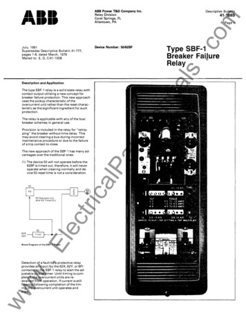
July, 1991Supersedes Descriptive Bulletin 41-777,Device Number: 50/62BFpages 1-8, dated March, 1979The type SBF-1 relay is a solid state relay withcontact output utilizing a new concept forbreaker failure protection. This new approachuses the pickup characteristic of theovercurrent unit rather than the reset charac teristic as the significant ingredient for suchprotection.The relay is applicable with any of the bus!"breaker schemes in general use.Provision is included in the relay for "retrip ping" the breaker without time delay. Thismay avoid clearing a bus during incorrectmaintenance procedure or due to the failureof a trip contact to close.The new approach of the SBF-1 has many ad vantages over the traditional ones:(1) The device 50 will not operate before the62BF is timed out, therefore, it will neveroperate when clearing normally and de cavice 50 reset time is not a consideration.50.E62Ylec6262XtriFD50 Operates onlyafter 62 Timed OutBlock Diagram of the SBF-1 RelayDetection of a fault by a protective relayprovides an input (by the 62X, 62Y, or BFIwcontacts) to the SBF-1 relay to start the ad justable pickup timer. Until timing is com pleted, the overcurrent units are re strained from operation. If current is stillwwflowing following completion of the tim ing, the overcurrent unit operates andtrips.lPDescription and Application41-1885Page 1Type SBF-1Breaker FailureRelayartManualsMailed to: E, 0, C/41-100BDescriptive BulletinomABB Power T&D Company Inc.Relay DivisionCoral Springs, FLAllentown, PA.cjllill,.'1.1.
Descriptive Bulletinom4-1888(2) It permits shorter margin and shorteroverall clearing times, and will give a netsaving of 1-2 cycles over the traditionalapproach.cPage 2FaultOccursNormal Clearing tmg TrmeartManuals(a) Traditional schemeTotal clearing time protective relay (breaker inter rupting time x 2) max. 50 resettime margin 86BF .(A)ReseIIMarginIInoperativeBreaker62 TimerSetting62X62YBFI5086BFLocal BackupBreaker Clearing--,JLocal Backup Breaker Failure Total Clearing TimeITFRTripRemote BackupBreaker ClearingRemote Backup Breaker Failure Total Clearing TrmeTime Chart of the Traditional Breaker Failure Scheme NormalCleanngProtectiveRelaylec(3) The overall clearing time for the newscheme varies with fault current level. Thehigher the fault current, the faster thebreaker failure clearing time. This is con sistent with the requirements of systemstability.EThe pickup time of the overcurrent units inthe SBF-1 relay is 3-8 millisecond for faultcurrent level from 2-20 times its tap set ting.www(4) The overcurrent unit will never operatewhen c learing normally so it can be setlower than load current, if necessary.Thisavoids delayed tripping associated withlow current until other breakers clear.BreakerInterrupting TimeMarginInoperativeBreakertriEqu. (e) shows that the saving in totalclearing time e quals the device 50max. reset time. The maximum resettime is one cycle for the SBFU relayand is 2 cycles for the Ke-4 relay.Normal Clearing TimelP-FaultOccursca(b) New schemeTotal clearing time protective relay (breaker inter rupting time x 2) margin 86BF . . . . (B)equ. (A) (B)(Saving in clearing time) max. 50reset time . . .(e).62X62YBFI62 TrmerSetting50PickupTimeControl Trmer Setting86BFLocal BackupBreaker Clearing-'I·1ILocal Backup Breaker Failure Total Clearing TimeTFRTripRemote BackupBreaker ClearingRemote Backup Breaker Failure Total Clearing TimeTime Chart of the SBF·' SchemeOperationThe operation of the SBF-1 is somewhat dif ferent than the conventional breaker failurerelay. It may be summarized by saying thatthe breaker failure relay timer is started byonly the BFI (62X) input rather than the BFIand the overcurrent fault detector. Thebreaker failure timer controls the fault detec tor so that after it ti mes out, the overcurrentsignal (if present) is connected to the level de tector. This arrangement keeps theovercurrent input transformer load at a lowlevel.Fast reset of the secondary voltage of 3ms.or less, even at very high multiples ofpickup current is permitted. By use of an addi tional timer (called the control timer) thebreaker failure timer is reset after it times out,as well as the X seal-in relay.July, 1991
Descriptive Bulletinom41-1885.cPage 3CharacteristicsOvercurrent unit range0.5 to 13.5 amperes10 Amperes (250 amperes for 1 sec.)Pickup time of olc units3 (min.) to 8 (max.) ms. for current level of 2X to 20X of setting.Breaker failure timer18 to 175 ms. continuously adjustableartManualsContinuous RatingControl timer150 to 250 ms. continuously adjustableBattery drain (125Vdc)standby 0timing 95 rnA.tripping 130 rnA.Output4 (N.O.) AR contact outputs, with 2 ICS, one telephone relay contact can replace an AR contactfor retrip function.Seal-inTelephone relay contact seal-in for(1) BFI contact bounce,(2) Close-in 3-phase fault when memory action of the distance relay is decayed.Voltage level detectorTo restrain the relay from operating if dc supply voltage is below 60% of its rated value.dc input operate range80 to 110% of rated. Max. Continuous input 110% of rated.Operate temperature rangeSImplified Internal SchematicWhenUsedNotes:To obtain AR contact output move yellow lead from terminal11 to terminal12.(Ll. (Rl. (LC) & (RC) denote left hand, right hand, left center &right center positions.25W Resistors(See Note)Volts DClPYellow Lead(See Note)RAca(See Table)AR RelayReed ghtIN2986824 VDC(See Table)Red HandleTest SwitchTermmalFurther InformationwCurrent Test JackwwFigure 1. Simplified Internal Schematic Type SBF·1July, 1991Sub 27758813List Prices: PL 41-020Technical Data: TO 41-025Instructions: IL 41-776.5Flexitest Case Dimensions: DB 41-076Other Protective Relays:Application Selector Guide, TO 41-016
Descriptive Bulletinom41-1885Page 4f'-I 6 .,62.;-----.J62·'18--,-sXILISeal In:cJgJ.62·'-,-,52aARIRCItOptional Complementto Overcurrent UnitsRedLead ,gARILI62·' '---.r-----"To AetrlpBreaker 52-1(To Obtain ARContact OutputMove Red Lead,fromTerminal 11to Terminal 12)868 FIFor High Speed TripAdjacent Breakersor Other Aux FunctionsartManualstSPP6DC PosRequired Where ProtectedBreaker Isolates aTransformerDC PosZADC NegTypical 86BF and/or Relay Aux Functions1. Trip Breakers connected to same bus section.2. Block all automatic reclosing.13. Block manual closing.DC NegSPPtDEVDescription4. Key transfer tri p transmitters to trip remote breakers and52Circuit Breaker5. Stop "Blocking" carrier.62SBF·' Breaker Failure Relay62S.62Y86 BFCr----.rrv-,""t"".,.".rv-.-- -"'":'N"'-'---N,.,. ,-.r, rv--.62-2 .-lP8 shielded control cable & ground both ends per switchyardruns where surge voltage may exceed2500 volts rear.'464C78Ring Bus or Breaker and a Half Scheme.-voltage may exceed2500 volts peaktWhen surge voltage may exceed2500 volts peak useTransformer Lockout RelayFigure 2. DC External Connection for Type SBF-l Breaker Failure Relay.rr-.tSPP surge protection capacitor to be used when surgeBreaker Failure Initiate ContactsBreaker Failure Lockout Relay86TIAblock reclosing.IASingle Breaker Schemerv-. Arn.8rY"\.C62-2.,.3 2( 18 When 62·216. Usedl . '7caA8 CTranmlsslon LineorTransformer \rl; r 62I21 f-I0§22-. -,F622SBF·' Relayfor Breaker52·2""' 74-62-'. IA-yR.ltriSPPt .C""'3r7 'IIB When62.'fP- Usedl--,r"" R'I ,610lec4 . f-lSPPtC62·'.-562·'"" -7-r---rBackuprRelaysr'--r-.E Relays t SPP Surge ProtectionA8CTransmission Line orTransformerCapacitors to be UsedWhen Surge Voltage MayExceed 2500 Volts Peak1464C77DEVDescription52Circuit Breaker62SBF-' Breaker Failure RelaywwwFigure 3. AC External Connection for Type SBF-l Breaker Failure Relayf2eJuly. 1991
ABB Power T&D Company Inc.Relay DivisionCoral Springs, FLAllentown, PAtManuals.comDescriptive Bulletin41-188SPage 5Type SBF-1Breaker FailureRelayJuly, 1991Supersedes TD 41·020, Type SBF·1 onpage 37, dated November, 1987Mailed to: E, D, C/41-100BBreaker Failure Relay, Solid State, Contact Output (Device Number: 50/62 BF)CurrentRange0.5-13.5ASBF-lBFITimerNo. ofOvercurrentUnitsControlTimer25-175 ms3150-250 ms48 Vde125 VdeTrippingVoltageSwitch Oc21CSUnits/relay0.2/2.0amp 5B8131529F93AOlFT·321529F93A02 250 Vde1529F93A0348 Vde125 Vde250 Vde1529F93A171529F93A071529F93A1525-175 ms150-250 ms50-500 ms150-600 ms3125 Vde25-175 ms150-250 ms448 Vde125 Vde250 Vdeca150-600 ms3lec0.5-13.5A350-500 mstri.05-1.3AIndicatingContactorlP(utilizesAR RelayOutput)48 Vde125 Vde250 775B8131529F93A041529F93A05 1529F93A06150-600 ms448 Vde125 Vde250 Vde1529F93A141529F93A121529F93A16100-1000 ms200-1100 ms4125 Vde1529F93All.E50-500 mswDenotes item available from stock.ww ControlVoltagearType@ICS: Indicating Contactor Switch (dc current operated)Rating of ICS unit used in specific types of relays is shownhaving seal-in contacts and indicating target which areactuated when the ICS coil is energized at or abovein price tables. All other ratings must be negotiated.pickup current setting. Suitable for dc control voltages upWhen ac current is necessary in a control trip circuit. theto and including 250 volts dc. Two current ranges areavailable:ICS unit can be replaced by an ACS unit.(1) 0.2/2.0 amps dc, with tapped coil.The ACS unit may be supplied in place of an ICS unit at(2) 1.0 amp dc, without taps.no additional cost. Specify system voltage rating on order.
4 (N.O.) AR contact outputs, with 2ICS, one telephone relay contact can replace an AR contact for retrip function. Telephone relay contact seal-in for (1) BFI contact bounce, (2) Close-in 3-phase fault when memory action of the distance relay is decayed. To restrain the relay from operat