Transcription
Product ManualABB i-bus EIB / KNXDisplay and Control TableauMT701.2Intelligent Installation System
ContentsPage1Introduction . . . . . . . . . . . . . . . . . . . . . . . . . . . . . . . . . . . . . . .52Device technology . . . . . . . . . . . . . . . . . . . . . . . . . . . . . . . . . .73Application and planning3.13.1.13.1.23.1.33.1.4General . . . . . . . . . . . . . . . . . . . . . . . . . . . . . . . . . . . . . . . . . . .Page setup . . . . . . . . . . . . . . . . . . . . . . . . . . . . . . . . . . . . . . . .Menu structure . . . . . . . . . . . . . . . . . . . . . . . . . . . . . . . . . . . . . .Functions . . . . . . . . . . . . . . . . . . . . . . . . . . . . . . . . . . . . . . . . . .Password protection . . . . . . . . . . . . . . . . . . . . . . . . . . . . . . . . ined pages and functions . . . . . . . . . . . . . . . . . . . . . .System page . . . . . . . . . . . . . . . . . . . . . . . . . . . . . . . . . . . . . . .Timer page . . . . . . . . . . . . . . . . . . . . . . . . . . . . . . . . . . . . . . . .Fault message page . . . . . . . . . . . . . . . . . . . . . . . . . . . . . . . . .Timing elements . . . . . . . . . . . . . . . . . . . . . . . . . . . . . . . . . . . .Logic . . . . . . . . . . . . . . . . . . . . . . . . . . . . . . . . . . . . . . . . . . . . .Lightscapes page . . . . . . . . . . . . . . . . . . . . . . . . . . . . . . . . . . .141416171818194Configuration and programming4.1Application program . . . . . . . . . . . . . . . . . . . . . . . . . . . . . . . .214.24.2.14.2.24.2.34.2.44.2.54.2.6Menu bar and taskbar . . . . . . . . . . . . . . . . . . . . . . . . . . . . . . .“Device” option . . . . . . . . . . . . . . . . . . . . . . . . . . . . . . . . . . . . .“Configuration” option . . . . . . . . . . . . . . . . . . . . . . . . . . . . . . . .“RS232 download” option . . . . . . . . . . . . . . . . . . . . . . . . . . . . .“View” option . . . . . . . . . . . . . . . . . . . . . . . . . . . . . . . . . . . . . . .“Setting” option . . . . . . . . . . . . . . . . . . . . . . . . . . . . . . . . . . . . .Other symbols . . . . . . . . . . . . . . . . . . . . . . . . . . . . . . . . . . . . . .232323242426294.3Device parameters . . . . . . . . . . . . . . . . . . . . . . . . . . . . . . . . .304.44.4.14.4.24.4.3General parameters . . . . . . . . . . . . . . . . . . . . . . . . . . . . . . . .Page parameters . . . . . . . . . . . . . . . . . . . . . . . . . . . . . . . . . . . .Display parameters . . . . . . . . . . . . . . . . . . . . . . . . . . . . . . . . . .Push button parameters . . . . . . . . . . . . . . . . . . . . . . . . . . . . . .8Parameters for predefined functions . . . . . . . . . . . . . . . . . . .System page . . . . . . . . . . . . . . . . . . . . . . . . . . . . . . . . . . . . . . .Timer page . . . . . . . . . . . . . . . . . . . . . . . . . . . . . . . . . . . . . . . .Timer buttons . . . . . . . . . . . . . . . . . . . . . . . . . . . . . . . . . . . . . . .Fault messages . . . . . . . . . . . . . . . . . . . . . . . . . . . . . . . . . . . . .Timing elements . . . . . . . . . . . . . . . . . . . . . . . . . . . . . . . . . . . .Logic – Logic Gatings . . . . . . . . . . . . . . . . . . . . . . . . . . . . . . . .Logic – Multiplexers . . . . . . . . . . . . . . . . . . . . . . . . . . . . . . . . . .Lightscapes . . . . . . . . . . . . . . . . . . . . . . . . . . . . . . . . . . . . . . . .4545464850525455574.64.6.14.6.2Group addresses and communication objects . . . . . . . . . . .Group addresses . . . . . . . . . . . . . . . . . . . . . . . . . . . . . . . . . . . .Communication objects . . . . . . . . . . . . . . . . . . . . . . . . . . . . . . .6161623
ContentsSeite5Appendix5.1Key table for the lightscape extension object . . . . . . . . . . .635.2Key table for the communication object“Operation mode Konnex” . . . . . . . . . . . . . . . . . . . . . . . . . . .64Ordering information . . . . . . . . . . . . . . . . . . . . . . . . . . . . . . . .645.34
ABB i-bus EIB1IntroductionIntroductionThe display and control tableau MT701.2 is an ABB i-bus EIB product for the– display and visualisation of switching states, status and fault signals on anLCD panel,– central control of EIB devices,– setting of lightscapes and switching times,– issue of visual and acoustic warning signals,– display of measured values and setting of limit values for measured-valuemonitoring as well as– execution of timers, logic functions and multiplexer functions.The display and control tableau is intended for flush-mounted or cavity wallinstallation. The flush-type box UP-KAST 2 is available for this purpose.The look of the display and control tableau is completed with the cover frameT-RAHM.Both the display and control tableau and the cover frame T-RAHM areavailable in white and silver.The connection to the EIB is established via a bus connecting terminal.The device requires an additional 230 V AC power supply.The display and control tableau is parameterised via a plug-in in the ETSprogram. The parameterisation is downloaded directly to the device via anRS 232 interface. Minor changes can also be downloaded to the device viathe EIB.The backlighting of the LCD display can either be switched on or off via anoperator button on the device, via an EIB telegram or automatically oncea set period has elapsed. The contrast setting can be adjusted directly viaoperator buttons on the device.Up to 16 display elements can be indicated on the LC display with 240 x 128pixels. These display elements can be arranged in lines or freely positionedon the panel.Up to 50 freely programmable pages can be created per device. It is possibleto jump from one page to another using a freely programmable menustructure. Access to a page can be protected via a password. A “.bmp” graphic can also be stored on each page as a background image. It is thereforealso possible to carry out simple visualisation functions.Limit values including hysteresis can be set for measured-value monitoring.When the value exceeds or falls below a set limit value, EIB telegrams canbe sent or a message can be displayed e.g. via a fault message page.The display and control tableau manages up to 50 fault signals. When analarm occurs, a fault message page can be retrieved and a warning tone isemitted. The alarms can be acknowledged. The acknowledgement can besent as a telegram via the EIB. The last 100 alarm events are stored in themessage list.5
ABB i-bus EIBIntroductionOn the timer page, there are 16 channels available for entering up to8 switching times per channel. Switching or value telegrams can begenerated on the EIB as an event for a switching time.Up to 24 lightscapes with a total of 32 group addresses can be set andmodified directly on the display and control tableau and via the EIB.Up to 80 logic operations, 40 timing elements and 12 multiplexers areavailable as logic functions as well as disable and filter functions. The resultof a logic function can either be sent as a telegram via the EIB or displayedas a message e.g. also via an alarm page.The date and time can be set on the display and control tableau or receivedvia the EIB. The display and control tableau can also be used as a masterclock and send the date and time via the EIB.6
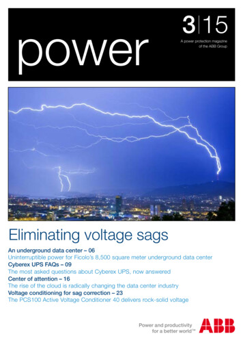
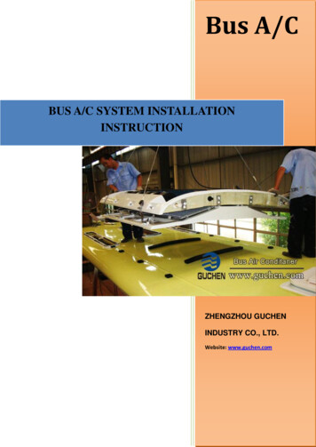
Display and control tableauMT701.2, , GH Q605 0059 R000 ABB i-bus EIB2Device technologyThe display and control tableau MT701.2 is an ABB i-bus EIB product for the– display and visualisation of switching states, status and fault signals on anLCD panel,– central control of EIB devices,– setting of lightscapes and switching times,– issue of visual and acoustic warning signals,– display of measured values and setting of limit values for measured-valuemonitoring as well as– execution of timers, logic functions and multiplexer functions.The display and control tableau is intended for flush-mounted or cavity wallinstallation. The flush-type box UP-KAST 2 is available for this purpose.The look of the display and control tableau is completed with the cover frameT-RAHM.The connection to the EIB is established via a bus connecting terminal.The device requires an additional 230 V AC power supply.Technical dataPower supplyOperating and display elementsConnectionsType of protectionAmbient temperature rangeDesign–––––– Red LED and push button– Reset button– 230 V sMounting depthWeightCertificationCE norm–––––ColourMains connectionPower consumptionLight button2 cursor keys4 shift keys230 V AC, /– 10 %, 50 60 Hztyp. 10 mALCD lighting ON/OFFUP/DOWN or FORWARD/BACKSwitching between display pages orselection of menu itemsFor entering the physical addressFor resetting the device2 screw terminals for L and NWire range:Finely stranded: 0.2 – 2.5 mm2Single-core: 0.2 – 4.0 mm2Bus connecting terminalEIBIP 43, EN 60 529Operation– 5 C . 45 CStorage– 25 C . 45 CTransport– 25 C . 45 CFlush-mounted housing for insertionin flush-type boxMT701.2, WSwhiteMT701.2, SRsilverFlush-mounted for installation incavity walls125 x 213 x 68 mm (H x W x D)75 mm incl. flush-type box0.86 kgEIB-certifiedin accordance with the EMCguideline and the low voltage guideline7
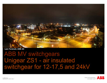
ABB i-bus EIBDisplay and control tableauMT701.2, , GH Q605 0059 R000 Application programsMax. number ofcommunication objectsMax. number ofgroup addressesMax. number ofassociationsDisplay and control tableau /2Circuit diagramLNNL143526781 Power supply 230 V AC2 Bus connecting terminal3 RS 2324 Programming button/LED5 Reset buttonDimension drawing1251091616 31185.56.5213179252168178
ABB i-bus EIBNoteDisplay and control tableauMT701.2, , GH Q605 0059 R000 The programming is carried out with ETS2 V1.2 from version ETS2 V1.2aonwards as well as ETS2 V1.3. The installation file “MT701 2 SOW de .exe” contains the application program as a file with the name “MT701 2.vd2”.The installation file must be executed before the product data is imported.The plug-in is installed in the directory “./ETS./2/MT701/.” viaa setup dialog while the product data (“MT701 2.vd2” file) is stored in adirectory of your choice. The product data (“MT701 2.vd2” file) can nowbe imported into the ETS database.The application program is downloaded directly into the display and controltableau via an RS 232 connection. If a download via a direct RS 232 connection can only be carried out from the ETS project design module, it meansthat the commissioning PC has a second RS 232 interface which cannot beaccessed by the ETS software.The application program can also be downloaded into the display and controltableau via the EIB. As the download via the EIB takes place at a relativelyslow rate, it is only recommended for carrying out minor changes. A download via the EIB is carried out from the ETS commissioning module.9
ABB i-bus EIB3Application andplanning3.1General3.1.1 Page setupApplication and planningUp to 50 freely definable display pages can be created in each project.The structure of a freely definable display page is shown in Fig. 1.Fig. 1: Structure of a freely definable display pageAll the text can be freely parameterised. The heading is centred at the topof the page. There are two lines of text available for the push buttons in therespective push button field. All other text can be freely positioned in theeight lines between the heading and the buttons.The cursor is moved from one text element to the next via the arrow keyson the device. Depending on which text element is selected by the cursor,another function and label can be stored for the push buttons.It can be set via a parameter whether the text can be selected with the cursorvia the arrow keys. If the text cannot be selected, there are no functionsstored for this text.It is possible to display a background image on each page. It is thereforepossible to create a simple visualisation screen by positioning the text anddisplay elements accordingly (see Fig. 2).10
ABB i-bus EIBApplication and planningFig. 2: Simple visualisation screenUser-defined characters can also be displayed instead of the text. It is therefore possible for example to create a light bulb or an open/closed blind usingpixels.Up to 25 background images can be used in total per project. A backgroundimage can be displayed on an unlimited number of pages.3.1.2 Menu structureIt is possible to switch from one page to another as required. The predefinedpages can also be retrieved from the freely defined pages.When creating the menu structure, it should be ensured that the user caneasily comprehend which menu he is in and how he can find and executethe required function. A tree structure with a main menu and function pagesor submenus is often the most suitable method for giving a clear overview ofthe menu structure (see Fig. 3).Fig. 3: Menu structureA freely defined page can be parameterised as a start page. If the device isnot operated for a set time, the display and control tableau automaticallyjumps to the start page so that the same page is always visible at the startof the operation.11
ABB i-bus EIBApplication and planning3.1.3 FunctionsEach display element can consist of the following six parts (see Fig. 4):– parameterised text,– display,– button 1 to button 4.Fig. 4: Parts of a display elementNot all the parts of a display element need to be used. A display elementcan for example only contain fixed text and no display or push button functionor can only contain a display without any explanatory text or push buttonfunction.Each of the six parts of a display element can be parameterised independently. As the individual parts frequently form a unit, a display element canalso be configured as a functional module e.g.:––––––Text:Display:Key 1:Key 2:Key 3:Key 4:Shutter,Open/closed,UpDownAny (e.g. Move to position 1)Any (e.g. Move to position 2)In the case of a functional module, a standard assignment of the individualparts of the display element is suggested and common communicationobjects are available for the display element as a whole.A display element can execute or indicate the following functions anddisplays:– Text display,– Switching,– Dimming,– Shutter,– Value,– Lightscape,– Date,– Time,– ASCII text,– Operator prompting– Page call.12
ABB i-bus EIBApplication and planning3.1.4 Password protectionIndividual display pages can be protected with passwords against accessby unauthorized persons. There are five password levels. The level “no password protection” enables the user to retrieve the page without entering apassword. There is a password for each of the password levels 1 to 4.If the user wishes to change to a display page with a higher password levelthan the current one, he must enter the relevant password. It is possible tochange to a page with a lower or identical password level at any time withoutentering a password.The password consists of a five-digit number from 1 to 4 and is entered usingthe buttons on the display and control tableau (see Fig. 5).Fig. 5: Entering the passwordThe passwords can be changed on the system page. The following passwords are selected as preset options after the initial download:––––Password level 1:Password level 2:Password level 3:Password level 4:11111222223333344444The passwords are not overwritten during all subsequent downloadsbut can only be changed via the system page. The password for thesystem page must therefore be kept somewhere safe!13
ABB i-bus EIB3.2Application and planningPredefined pages andfunctions3.2.1 System pageIt is possible to carry out the following settings on the system page or viewthe following information (see Fig. 6):– Contrast setting,– Date,– Time,– Passwords,– Message list.Fig. 6: System pageContrast settingFor setting the brightness of the backlighting via button 1 (“Contrast ”) andbutton 2 (“Contrast –") (see Fig. 6). Button 3 (“Contrast Save”) must be pressed in order to save the setting.14
ABB i-bus EIBApplication and planningDateTimeFor setting the date or time. The “Date” or “Time” page is recalled with button1 (“Change”) (see Fig. 7). The required digit can be selected via buttons 1(“ ”) and 2 (“ ”).The setting is carried out via the arrow keys. Button 3 (“Set”) must be pressed to save the setting.Fig. 7: Change datePasswordsFor setting the passwords. The “Passwords” page is retrieved with button 1(“Change”) (see Fig. 8). Button 3 (“Save”) must be pressed to store the setting.Fig. 8: Change passwords15
ABB i-bus EIBApplication and planningMessage listFor displaying the last fault message events. The message list is displayedvia button 1 (“Display”) (see Fig. 9).Fig. 9: Message list3.2.2 Timer pageA timer with up to 16 channels can be created in each project. The requiredchannels must be created in ETS. The switching times are set via the timerpage directly on the display and control tableau. The timer page lists all theparameterised channels as well as the switching command which was lastsent to the connected group address (see Fig. 10).Fig. 10: Timer pageThe corresponding switching time page is opened (see Fig. 11) by selectingthe required channel and pressing button 1 (“Change”). The time, value andthe days of the week can be selected in sequence via button 1 (“ ”).The setting is carried out via the arrow keys. Button 3 (“Save”) must be pressed to store the setting.The switching times are only carried out on the days of the week that arespecified on the switching time page.16
ABB i-bus EIBApplication and planningFig. 11: Switching time page3.2.3 Fault message pageUp to 50 fault message pages can be created in each project. The requiredfault message pages must be created in the ETS program. If a telegram isreceived at the associated fault message object, the corresponding faultmessage page is opened (see Fig. 12).Fig. 12: Fault message pageThe fault message page displays the date and time of the fault message, theparameterised text as well as the number of currently active fault messages.Depending on the parameter settings, an acoustic fault signal is emittedsimultaneously when an alarm occurs.The alarm can be acknowledged via button 3 (“Acknowledge”) which alsostops the acoustic alarm signal. The acknowledgement can also be sent viathe EIB and entered in the message list. The message window is closed withbutton 4 (“Back”) and the previously active display page is shown. If the faultmessage has not yet been acknowledged, it is acknowledged simultaneously.17
ABB i-bus EIBApplication and planningWith the corresponding parameterisation, it is possible to set that the faultmessage is reported again after an adjustable period even after an acknowledgement, if the cause of the fault message has still not been rectified i.e. notelegrams have been received with the opposite value.All fault messages, acknowledgements and reset fault messages can beentered in the message list (see Fig. 13). The last 100 fault message eventsare stored in the message list with the date, time and text as well as information about whether it is an incoming message (“I” – the door has been opened), an acknowledgement (“A” – acknowledgement on the display andcontrol tableau) or an outgoing message (“O” – the door has been closedagain). The message list is retrieved via the system page.Fig. 13: Message list3.2.4 Timing elementsUp to 40 timing elements can be created in each project. Using a timingelement, the routing of a telegram can be delayed (ON and/or OFF delay),inverted and/or disabled via a disable object.3.2.5 LogicLogic gatingsUp to 80 logic gates (AND, OR or EXCLUSIVE OR) can be created in eachproject. Up to 8 inputs can be parameterised for each logic gate, wherebyit is possible to invert all the inputs as well as the output. The logic gate canbe blocked via a disable object and the output object can be filtered according to its value (send only “1” telegrams or send only “0” telegrams).MultiplexersUp to 12 multiplexers (1 to 2 multiplexers or 1 to 4 multiplexers) can be created in each project. Depending on the value of the control object or objects,the value of the input object is only sent to one of the two or four outputs.18
ABB i-bus EIBApplication and planningTruth table “1 to 2 multiplexers”:InputControl Output Outputobj. 112Value0Value–Value1–ValueTruth table “1 to 4 multiplexers”:InputControl Control Outputobj. 1obj. 21Value00ValueValue01–Value10–Value11–3.2.6 Lightscapes ut4–––ValueUp to 24 lightscapes can be created in each project. There is a total of32 group addresses available for all the lightscapes. The lightscapes areretrieved and modified via the “Lightscapes” page (see Fig. 14).Fig. 14: Lightscapes pageTo recall a lightscape, the cursor must be positioned on the required lightscapeand button 1 (“Call/Save”) must be pressed briefly ( 5 seconds). If button 1is held down for longer than 5 seconds, a status query is started via the EIBfor all the lightscape group addresses and the current switching states areadopted as new lightscape values. Alternatively, the lightscape values can bemodified via button 2 (“Lightsc. Change”) (see Fig. 15). The name of thelightscape is modified via button 3 (“Text Change”) (see Fig. 16).19
ABB i-bus EIBApplication and planningFig. 15: Change lightscapeIt can be set for each lightscape on the display and control tableau whichvalue is sent via the connected group address when the lightscape is retrieved. The cursor is placed on the corresponding group address and the required lightscape value is set via buttons 1 (“On/Shut/ ”) and 2 (“Off/Open/–”).If the buttons 1 or 2 are pushed more than once, the option “unchanged” is set.Fig. 16: Change lightscape textTo change the name of the lightscape, a character is selected via buttons 1(“ ”) and 2 (“ ”) as well as the arrow keys and transferred into the text fieldwith button 3 (“Enter”). The function of the 4 buttons is changed by pressingbutton 4 (“Level 2”).In level 2, the marked character is deleted with button 1 (“Back”) and thecursor is moved one character forwards. The new text is stored with button 3(“Save”) and the change to the text is cancelled with button 2 (“Cancel”). Thepush button functions can be changed again by pressing button 4 (“Level 1”).20
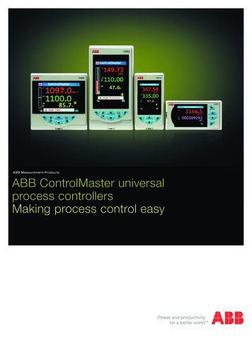
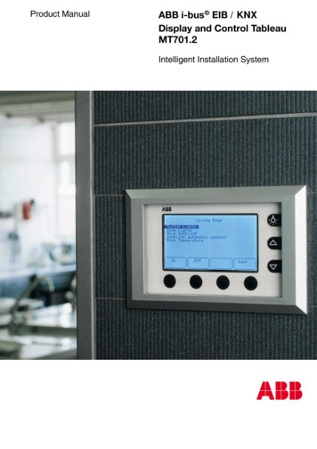
ABB i-bus EIBConfiguration and programmingDisplay and control tableau /2A lightscape that is parameterised in the display and control tableau can alsobe retrieved via a push button action directly from any freely parameterisablepage or via the EIB for example using an external push button. The sameapplies for the status query of all the lightscape group addresses and storingas a new lightscape value. Lightscapes can thus be retrieved and reconfigured without the lightscape page.4Configuration andprogramming4.1Application programThe display and control tableau MT701.2 is downloaded with the applicationprogram “Display and control tableau/2” via the ETS software from versionETS2 V1.2a onwards. The installation file “MT701 2 SOW de . .exe"contains the application program as a file with the name “MT701 2.vd2".The installation file must be executed before the product data is imported.The tool software is installed in the directory “./ETS./2/MT701/." via asetup dialog while the product data (“MT701 2.vd2" file) is stored in adirectory of your choice. The product data (“MT701 2.vd2" file) can now beimported into the ETS database.The product data is inserted into the project in the Building View of the ETSprogram. All the parameter settings and links are not programmed directly inETS but in a plug-in. The plug-in is a small subroutine to ETS which is usedto configure and program the device. The parameters and links that are set inthe plug-in are automatically adopted in the ETS program.The communication objects of the display and control tableau are only displayed as group objects in the Building View of ETS. They can only be editedin the plug-in (see Fig. 17).Fig. 17: Building View in ETSClick on the device with the right mouse button and select the option “Parameters” or double click on the device and select the “Parameters” button.The plug-in window opens (see Fig. 18).21
ABB i-bus EIBConfiguration and programmingDisplay and control tableau /2Fig. 18: MT701.2 plug-inIn addition to the name of the plug-in, the title bar also contains informationabout whether the plug-in has been opened from the ‘Project Design’ moduleor the ‘Commissioning/Test’ module of ETS.The menu bar and taskbar are located directly underneath the title bar.The plug-in configuration window is divided into three sections. All the configuration elements are listed in the left-hand section, such as the freely programmable pages with all the display elements and push button assignmentsas well as the internal and external group addresses. The parameters for theconfiguration element that is marked on the left are shown in the top righthand section. The context-sensitive hints or help information for the markedparameter are located in the bottom right-hand section (yellow).By clicking on a configuration element in the left-hand section, the associatedparameters are displayed in the top right-hand section and the correspondingicons are activated in the taskbar. If you click for example on the configuration element “Pages” followed by the symbol “Insert page”, a new page iscreated e.g. “[1] Page – Page”. By clicking on the configuration element "[1]Page – Page”, the associated parameters appear next to it on the right-handside.By clicking on a parameter, the context-sensitive help information for theparameter appears in the bottom right-hand section. It is advisable to openthe help window by selecting “Help” from the menu bar and placing it next tothe working area of the plug-in. Explanatory help text is thus available duringthe configuration. It is also possible to search for keywords via the help indexand display the corresponding help text.By clicking on the symbol “Back to the ETS”, you exit the plug-in and returnto the ETS project. Changes can then no longer be reversed.22
ABB i-bus EIB4.2Configuration and programmingDisplay and control tableau /2Menu bar and taskbar4.2.1 “Device” optionExport templateImport templateA project that has been created with the plug-in can be saved as a file andimported into another project as a copy. All the text and parameter settingsare thereby retained.When importing the template, you are asked whether the import should becarried out with the same group addresses or without existing links.It is therefore possible to just copy the template. The group addresses mustthen be linked again.PrintPrint previewFor printing or viewing the configuration documentation of the project onscreen including all the parameter settings and connections.Save backup data nowFor saving the project.Restore backupTo restore the project to the status at the time of the last save.The settings that have been made since the last save are undone.Back to the ETSFor exiting the plug-in module. The current configuration status is automatically stored and the data is transferred to the ETS project.All changes are saved when you exit the plug-in.It is no longer possible to undo any changes!4.2.2 “Configuration” optionNew configuration windowFor opening a further configuration window. When working in two or moreconfiguration windows, it is possible to work on the project in several placesat the same time without having to scroll up and down. This function is particularly suitable for linking group addresses and communication objects.Fold out allFold up allFor displaying the configuration elements in full including all the subdivisionsor for displaying the top level of all the configuration elements.Jump to objectWith this function, a defined object can be selected directly.Reset settingsTo return the settings to the default options at the start of the configuration.All the parameter settings and connections that have been carriedout are deleted. This command can only be undone(“Restore backup” in the “File” menu) if no save is carried out.23
ABB i-bus EIB4.2.3 “RS232 download” optionConfiguration and programmingDisplay and control tableau /2SetupFor setting the COM port and the baud rate.Start downloadFor downloading the configuration into the display and control tableau via thedirect RS 232 connection. If a download via a direct RS 232 connection canonly be carried out from the Project Design module in ETS, the commissioning PC has a second RS 232 interface which cannot be accessed from theETS program.A download via the EIB is carried out in the ‘Commissioning/Test’ module ofthe ETS program.4.2.4 “View” optionNew configuration windowFor opening a further configuration window. When working in two or moreconfiguration windows, it is possible to work on the project in several placesat the same time without having to scroll up and down. This function is particularly suitable for linking group addresses and communication objects.Resources monitorThe resources monitor indicates the group addresses, communicationobjects and connections that have already been used and those that are stillavailable.Fig. 19: Resources monitorCharacter setFor displaying the available characters (see Fig. 20).The characters in the grey area are fixed and cannot be modified.User-defined characters can be created and modified in the white area.Via the option “File” in the menu bar, individual characters can be importedinto the project (“Import”), user-defined characters can be exported for use inother projects (“Export”) and the “Character set” dialog window can be closed(“Exit”).24
ABB i-bus EIBConfiguration and programmingDisplay and control tableau /2Fig. 20: Character setBy marking a character with a white background and selecting the option“Edit” from the menu bar, the “Edit character” dialog window opens(see Fig.
The display and control tableau is intended for flush-mounted or cavity wall installation. The flush-type box UP-KAST 2 is available for this purpose. The look of the display and control tableau is completed with the cover frame T-RAHM. Both the display and control tableau and the cover frame T-RAHM are available in white and silver.