Transcription
Automatic Railway Gate Controlusing AudrinobyNameRoll No.Registration No:Bikram Das11700314030Chaity Roy11700314031Tanuj KumarMajumdarMadhurima Das11700315145141170110212 of 20142015141170110213 of 20142015151170120046 of 20152016151170120031 of 2015201611700315130A comprehensive project report has been submitted in partial fulfillment ofthe requirements for the degree ofBachelor of TechnologyinELECTRONICS & COMMUNICATION ENGINEERINGUnder the supervision ofDr. Soham SarkarAssistant ProfessorDepartment of Electronics & Communication EngineeringRCC INSTITUTE OF INFORMATION TECHNOLOGYAffiliated to Maulana Abul Kalam Azad University of Technology, WestBengalCANAL SOUTH ROAD, BELIAGHATA, KOLKATA – 700015May,20181
CERTIFICATE OF APPROVALThis is to certify that the project titled “Automatic Railway Gate Control using Audrino”carried out byNameRoll No.Registration No:Bikram Das11700314030Chaity Roy11700314031Tanuj KumarMajumdarMadhurima Das11700315145141170110212 of 20142015141170110213 of 20142015151170120046 of 20152016151170120031 of 2015201611700315130for the partial fulfillment of the requirements for B.Tech degree in Electronics andCommunication Engineering from Maulana Abul Kalam Azad University ofTechnology, West Bengal is absolutely based on his own work under the supervisionof Dr. Soham sarkar The contents of this thesis, in full or in parts, have not beensubmitted to any other Institute or University for the award of any degree or diploma.Optional in case of External Supervisor.NA.Dr. Abhishek BasuHead of the Department (ECE)RCC Institute of Information Technology2.Dr. Soham SarkarProfessor , Dept. of ECERCC Institute of Information Technology
DECLARATION“We Do hereby declare that this submission is our own work conformed to thenorms and guidelines given in the Ethical Code of Conduct of the Institute and that,to the best of our knowledge and belief, it contains no material previously written byanother neither person nor material (data, theoretical analysis, figures, and text) whichhas been accepted for the award of any other degree or diploma of the university orother institute of higher learning, except where due acknowledgement has been madein the text.”.Bikram DasChaity RoyRegistration No141170110212 OF 2014-2015Roll No: 11700314030Registration No:141170110213 OF 2014-2015Roll No: 11700314031.Tanuj Kumar MajumdarMadhurima DasRegistration No:151170120046 OF 2015-2016Roll No: 11700315145Registration No:151170120031 OF 2015-2016Roll No: 11700315130Date:Place:3
CERTIFICATE of ACCEPTANCEThis is to certify that the project titled “Automatic Railway Gate Control usingAudrino” carried out byNameRoll No.Registration No:Bikram Das11700314030Chaity Roy11700314031Tanuj KumarMajumdarMadhurima Das11700315145141170110212 of 20142015141170110213 of 20142015151170120046 of 20152016151170120031 of 2015201611700315130is hereby recommended to be accepted for the partial fulfillment of the requirementsfor B.Tech degree in Electronics and Communication Engineering from Maulana AbulKalam Azad University of Technology, West BengalName of the Examiner Signature with Date1. 2. . .3. 4. . 4
ABSTRACTFrom this project we’ll know how to implement the automation in railway gate controlusing Audrino. Application of this project is the direct implementation in real world. Somecomponents will be required more but the main working principle will be same.Now, other alerting systems can also be developed by using Audrino. The main aimof this project is to reduce train accidents at railway level crossings to the minimum.5
CONTENTSCERTIFICATE .1DECLARATION . 3.CCERTIFICATEOFACCEPTANCE .4ABSTRACT . 5CONTENTS . 9LIST OF FIGURES . 7LIST OF TABLES . 8Introduction . 10.1.1problem defination . 11.1.2problem statement . 11.1.3analysis . 121.4outcome . 27.REFERENCE VicRoads (2014-08-26). "Trains & level crossings". VicRoads. Retrieved 2017-11-12.Rivanna Chapter, National Railway Historical Society (2005). "This Month inRailroad History: August". Retrieved 25 August 2006."Railways to eliminate over 6,000 unmanned level crossings". The Indian Express. 30 July2016.Lloyd's Register Rail (2007). "Study of pedestrian behaviour at public railwaycrossings". Public Transport Safety Victoria. Victoria, Australia.Mok, Shannon C; Savage, Ian (1 August 2005). "Why Has Safety Improved at RailHighway Grade Crossings?". Risk Analysis. 25 (4): 867–881.6
LIST OF FIGURESFig 1.Audrino UNO R3Fig 2.Atmel mega 328PFig 3.LN 293DFig 4.LM 358 ICFig 5.LM 358 IC internal CircuitryFig 6.IR LEDFig 7.PhotodiodeFig 8.IR sensor Module circuitFig 9.IR sensor ModuleFig 10.Stepper MotorFig 11.Audrino IDEFig 12.Circuit Diagram of prototype7
LIST OF TABLESTable 1PIN diagram of Atmel mega 328pTable 2.PIN diagram of LN 293D8
CONTENTSContents Introduction What is level crossing Required Components Descriptiopn of Components Circuit of prototype Working Principle Future Scope References9
Introduction1.1. Auromatic Railway Gate Control using AudrinoLevel crossing is that area where the rail line intersects with the road which is used bytransportation or other vehicles.To prevent accidents a system named “Level Crossing” hasbeen developed.But in early days all the level crossings are operated by humans.So humaninterference was mandatory.But,manual control is not erros free.The railway gate or levelcrossing is opened or closed by a gateman who was informed from the nearest railwaystation about the arrival of a train.There’re also many level crossings in India which are unmanned.So they are potentiallydangerous for road users.In India we must develop a prototype to be implemented to automatically control railwaygate upon arrival as well as departure of train.The project should not be too much expensivebut must be reliable.So we used Audrino uno R3 which is quite reliable as well asaffordable.We started to develop our project based upon 8051 microcontroller which is also cheaperthan Audrino.But in terms of of reliability and implementation of future featured weupgraded to audrino uno.10
1.2 what is a level crossing?A level crossing is an intersection where a railway line crosses a road or path at the samelevel, as opposed to the railway line crossing over or under using a bridge or tunnel. Theterm also applies when a light rail line with separate right-of-way or reserved track crosses aroad in the same fashion. Other names include railway level crossing, grade crossing, roadthrough railroad, railroad crossing, train crossing, and RXR.1.3History of level crossingThe history of level crossings depends on the location, but often early level crossings hada flagman in a nearby booth who would, on the approach of a train, wave a red flag orlantern to stop all traffic and clear the tracks. Gated crossings became commonplace in manyareas, as they protected the railway from people trespassing and livestock, and theyprotected the users of the crossing when closed by the signalman/gateman. In the secondquarter of the 20th century, manual or electrical closable gates that barricaded the roadwaystarted to be introduced, intended to be a complete barrier against intrusion of any roadtraffic onto the railway. Automatic crossings are now commonplace in some countries asmotor vehicles replaced horse-drawn vehicles and the need for animal protectiondiminished with time. Full, half or no barrier crossings superseded gated crossings,although crossings of older types can still be found in places. New technology is advancingto create new ways of protecting the railway from users of a level crossing, with one of themost recent being obstacle detection scanners fitted to some crossings in Europe.In rural regions with sparse traffic, the least expensive type of level crossing to operate isone without flagmen or gates, with only a warning sign posted. This type has been commonacross North America and in many developing countries.Some international rules have helped to harmonize level crossing. For instance, the 1968Vienne convention about signalisation routière: in its Chapitre III Signaux lumineux de circulation: Article 23b stand that one or twoblinking red fire indicates a car should stop, when if they are yellow the car can passwith caution.This has been implemented in many countries, including countries not being part of theVienna Convention. in its article 27, a stop line is suggested at grade crossingarticle 33, 34, 35 and 36 are specific to level crossing, because level crossing arerecognized as dangerousarticle 35 indicates a cross should exist when there is no barrier11
A majority of the level crossings in India were manually regulated. Signals and barriers areinstalled at all crossings while manual crossings are additionally required to have the handred and green signal flags. But Indian Railways aims at elimination of all unmannedcrossings and replacing it with manned crossings.2.Required Components1.2.3.4.5.6.7.8.Audrino Uno R3L293D motor drvierLm 358 ICIR sensor PairsStepper MotorBuzzerLEDsJumper Wires3.Description of components3.1.1.Audrino Uno R312
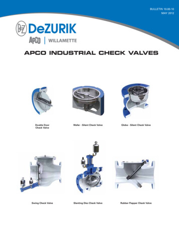
Fig 1. Audrino UNO R3The Arduino UNO is a widely used open-source microcontroller board based onthe ATmega328P microcontroller and developed by Arduino.cc.The board is equipped withsets of digital and analog input/output (I/O) pins that may be interfaced to variousexpansion boards (shields) and other circuits.[1] The board features 14 Digital pins and 6Analog pins. It is programmable with the Arduino IDE(Integrated DevelopmentEnvironment) via a type B USB cable. It can be powered by a USB cable or by an external 9volt battery, though it accepts voltages between 7 and 20 volts. It is also similar to theArduino Nano and Leonardo. The hardware reference design is distributed under a CreativeCommons Attribution Share-Alike 2.5 license and is available on the Arduino website.Layout and production files for some versions of the hardware are also available. "Uno"means one in Italian and was chosen to mark the release of Arduino Software (IDE) 1.0.TheUno board and version 1.0 of Arduino Software (IDE) were the reference versions ofArduino, now evolved to newer releases. The Uno board is the first in a series of USBArduino boards, and the reference model for the Arduino platform.[3] The ATmega328 onthe Arduino Uno comes preprogrammed with a bootloader that allows to upload new codeto it without the use of an external hardware programmer. It communicates using theoriginal STK500 protocol. The Uno also differs from all preceding boards in that it does notuse the FTDI USB-to-serial driver chip. Instead, it features the Atmega16U2 (Atmega8U2 upto version R2) programmed as a USB-to-serial converter.3.1.2 Technical Specifications Microcontroller: ATmega328POperating Voltage: 5vInput Voltage: 7-20vDigital I/O Pins: 14 (of which 6 provide PWM output)Analog Input Pins: 6DC Current per I/O Pin: 20 mADC Current for 3.3V Pin: 50 mAFlash Memory: 32 KB of which 0.5 KB used by bootloaderSRAM: 2 KBEEPROM: 1 KBClock Speed: 16 MHzLength: 68.6 mm13
Width: 53.4 mmWeight: 25 g3.1.3 PINSGeneral Pin functions LED: There is a built-in LED driven by digital pin 13. When the pin is HIGH value,the LED is on, when the pin is LOW, it's off.VIN: The input voltage to the Arduino/Genuino board when it's using an externalpower source (as opposed to 5 volts from the USB connection or other regulatedpower source). You can supply voltage through this pin, or, if supplying voltage viathe power jack, access it through this pin.5V: This pin outputs a regulated 5V from the regulator on the board. The board canbe supplied with power either from the DC power jack (7 - 20V), the USB connector(5V), or the VIN pin of the board (7-20V). Supplying voltage via the 5V or 3.3V pinsbypasses the regulator, and can damage the board.3V3: A 3.3 volt supply generated by the on-board regulator. Maximum current drawis 50 mA.GND: Ground pins.IOREF: This pin on the Arduino/Genuino board provides the voltage reference withwhich the microcontroller operates. A properly configured shield can read theIOREF pin voltage and select the appropriate power source or enable voltagetranslators on the outputs to work with the 5V or 3.3V.Reset: Typically used to add a reset button to shields which block the one on theboard.3.1.4Special Pin FunctionsEach of the 14 digital pins and 6 Analog pins on the Uno can be used as an input oroutput, using pinMode(),digitalWrite(), and digitalRead() functions. They operate at 5volts. Each pin can provide or receive 20 mA as recommended operating condition andhas an internal pull-up resistor (disconnected by default) of 20-50k ohm. A maximum of40mA is the value that must not be exceeded on any I/O pin to avoid permanent damageto the microcontroller.The Uno has 6 analog inputs, labeled A0 through A5, each ofwhich provide 10 bits of resolution (i.e. 1024 different values). By default they measurefrom ground to 5 volts, though is it possible to change the upper end of their rangeusing the AREF pin and the analogReference() function.In addition, some pins have specialized functions:14
Serial: pins 0 (RX) and 1 (TX). Used to receive (RX) and transmit (TX) TTL serialdata. These pins are connected to the corresponding pins of the ATmega8U2 USB-toTTL Serial chip.External Interrupts: pins 2 and 3. These pins can be configured to trigger aninterrupt on a low value, a rising or falling edge, or a change in value.PWM(Pulse Width Modulation) 3, 5, 6, 9, 10, and 11 Can provide 8-bit PWM outputwith the analogWrite() function.SPI(Serial Peripheral Interface): 10 (SS), 11 (MOSI), 12 (MISO), 13 (SCK). These pinssupport SPI communication using the SPI library.TWI(Two Wire Interface): A4 or SDA pin and A5 or SCL pin. Support TWIcommunication using the Wire library.AREF(Analog REFerence: Reference voltage for the analog inputs.3.1.5. CommunicationThe Arduino/Genuino Uno has a number of facilities for communicating with a computer,another Arduino/Genuino board, or other microcontrollers. The ATmega328 provides UARTTTL (5V) serial communication, which is available on digital pins 0 (RX) and 1 (TX). AnATmega16U2 on the board channels this serial communication over USB and appears as avirtual com port to software on the computer. The 16U2 firmware uses the standard USBCOM drivers, and no external driver is needed. However, on Windows, a .inf file isrequired. The Arduino Software (IDE) includes a serial monitor which allows simple textualdata to be sent to and from the board. The RX and TX LEDs on the board will flash whendata is being transmitted via the USB-to-serial chip and USB connection to the computer (butnot for serial communication on pins 0 and 1). A SoftwareSerial library allows serialcommunication on any of the Uno's digital pins.3.1.5.Automatic (Software) ResetRather than requiring a physical press of the reset button before an upload, theArduino/Genuino Uno board is designed in a way that allows it to be reset by softwarerunning on a connected computer. One of the hardware flow control lines (DTR) of theATmega8U2/16U2 is connected to the reset line of the ATmega328 via a 100 nanofaradcapacitor. When this line is asserted (taken low), the reset line drops long enough to reset thechip.[7]This setup has other implications. When the Uno is connected to either a computer runningMac OS X or Linux, it resets each time a connection is made to it from software (via USB).For the following half-second or so, the bootloader is running on the Uno. While it isprogrammed to ignore malformed data (i.e. anything besides an upload of new code), it willintercept the first few bytes of data sent to the board after a connection is opened.15
3.2 Atmel ATmega 328PThe Atmel 8-bit AVR RISC-based microcontroller combines 32 kB ISP flash memory withread-while-write capabilities, 1 kB EEPROM, 2 kB SRAM, 23 general purpose I/O lines, 32general purpose working registers, three flexible timer/counters with compare modes,internal and external interrupts, serial programmable USART, a byte-oriented 2-wire serialinterface, SPI serial port, 6-channel 10-bit A/D converter (8-channelsin TQFP and QFN/MLF packages), programmable watchdog timer with internal oscillator,and five software selectable power saving modes. The device operates between 1.8-5.5 volts.The device achieves throughput approaching 1 MIPS per MHz.Table 1.ParameterValueCPU type8-bit AVRPerformance20 MIPS at 20 MHz[2]Flash memory32 kBSRAM2 kBEEPROM1 kBPin count28-pin PDIP, MLF, 32-pin TQFP, MLF[2]Maximum operating frequency 20 MHzNumber of touch channels16Hardware QTouch Acquisition NoMaximum I/O pins1623
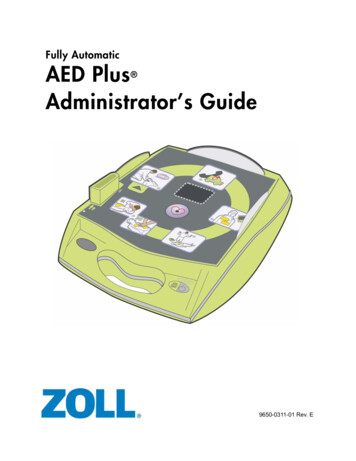
External interrupts2USB InterfaceNoUSB Speed–Fig 2. Atmel mega 328p3.3. L293D Motor DriverL293D is a dual H-bridge motor driver integrated circuit (IC). Motor drivers act as currentamplifiers since they take a low-current control signal and provide a higher-current signal.This higher current signal is used to drive the motors.L293D contains two inbuilt H-bridge driver circuits. In its common mode of operation, twoDC motors can be driven simultaneously, both in forward and reverse direction. The motoroperations of two motors can be controlled by input logic at pins 2 & 7 and 10 & 15. Inputlogic 00 or 11 will stop the corresponding motor. Logic 01 and 10 will rotate it in clockwiseand anticlockwise directions, respectively.17
Enable pins 1 and 9 (corresponding to the two motors) must be high for motors to startoperating. When an enable input is high, the associated driver gets enabled. As a result, theoutputs become active and work in phase with their inputs. Similarly, when the enable inputis low, that driver is disabled, and their outputs are off and in the high-impedance state.Fig 3. L293D Motor Driver18
3.3.2. PIN eEnable pin for Motor 1; active highInput 1 for Motor 1Output 1 for Motor 1Ground (0V)Ground (0V)Output 2 for Motor 1Input 2 for Motor 1Supply voltage for Motors; 9-12V (up to 36V)Enable pin for Motor 2; active highInput 1 for Motor 1Output 1 for Motor 1Ground (0V)Ground (0V)Output 2 for Motor 1Input2 for Motor 1Supply voltage; 5V (up to 36V)Enable 1,2Input 1Output 1GroundGroundOutput 2Input 2Vcc 2Enable 3,4Input 3Output 3GroundGroundOutput 4Input 4Vcc 1Table 23.4.1. LM 358 ICThe LM358 IC is a great, low power and easy to use dual channel op-amp IC. It is designedand introduced by national semiconductor. It consists of two internally frequencycompensated, high gain, independent op-amps. This IC is designed for specially to operatefrom a single power supply over a wide range of voltages. The LM358 IC is available in achip sized package and applications of this op amp include conventional op-amp circuits,19
DC gain blocks and transducer amplifiers. LM358 IC is a good, standard operationalamplifier and it is suitable for your needs. It can handle 3-32V DC supply & source up to20mA per channel. This op-amp is apt, if you want to operate two separate op-amps for asingle power supply. It’s available in an 8-pin DIP package.Fig 4 . LM358 IC3.4.2 PIN configurationThe pin diagram of LM358 IC comprises of 8 pins, where Pin-1 and pin-8 are o/p of the comparatorPin-2 and pin-6 are inverting i/psPin-3 and pin-5 are non inverting i/psPin-4 is GND terminalPin-8 is VCC 20
Fig 5. Internal circuitry config. Of LM 358 IC.3.4.3. Features of LM 358 ICThe features of the LM358 IC are It consists of two op-amps internally and frequency compensated for unity gainThe large voltage gain is 100 dBWide bandwidth is 1MHzRange of wide power supplies includes single and dual power suppliesRange of Single power supply is from 3V to 32VRange of dual power supplies is from or -1.5V to or -16VThe supply current drain is very low, i.e., 500 μA2mV low i/p offset voltageCommon mode i/p voltage range comprises groundThe power supply voltage and differential i/p voltages are similaro/p voltage swing is large.3.5. IR sensor kit using LM 358 IC3.5.1 IR LEDIR LED emits light, in the range of Infrared frequency. IR light is invisible to us as itswavelength (700nm – 1mm) is much higher than the visible light range. Everything whichproduce heat, emits infrared like for example our human body. Infrared have the sameproperties as visible light, like it can be focused, reflected and polarised like visible light .21
Fig 6. IR LED3.5.2 PhotodiodePhotodiode is considered as Light dependent Resistor (LDR), means it has very Highresistance in absence of light and become low when light falls on it. Photodiode is asemiconductor which has a P-N junction, operated in Reverse Bias, means it startconducting the current in reverse direction when Light falls on it, and the amount of currentflow is proportional to the amount of Light. This property makes it useful for IR detection.Fig 7. Photodiode3.5.3 IR sensor ModuleComponents IR pair (IR LED and Photodiode)IC LM358Resistor 100, 10k, 330 ohm22
Variable resistor – 10kLED3.5.4 Circuit Diagram of IR Sensor moduleFig 8. Circuit diagram of IR sensor moduleIR sensor module used in prototype23
Fig 9. IR sensor module3.5.5 Working methodWhen we turn ON the circuit there is no IR radiation towards photodiode and the Outputof the comparator is LOW. When we take some object (not black) in front of IR pair, then IRemitted by IR LED is reflected by the object and absorbed by the photodiode. Now whenreflected IR Falls on Photodiode, the voltage across photodiode drops, and the voltageacross series resistor R2 increases. When the voltage at Resistor R2 (which is connected tothe non-inverting end of comparator) gets higher than the voltage at inverting end, then theoutput becomes HIGH and LED turns ON.Voltage at inverting end, which is also called Threshold Voltage, can be set by rotatingthe variable resistor’s knob. Higher the voltage at inverting end (-), less sensitive thesensor and Lower the voltage at inverting end (-), more sensitive the sensor.3.6.1 Stepper MotorA stepper motor or step motor or stepping motor is a brushless DC electric motor thatdivides a full rotation into a number of equal steps. The motor's position can then becommanded to move and hold at one of these steps without any positionsensor for feedback (an open-loop controller), as long as the motor is carefully sized to theapplication in respect to torque and speed.Switched reluctance motors are very large stepping motors with a reduced pole count, andgenerally are closed-loop commutated.3.6.2 Fundamentals of Operation24
Fig 10. Steeper MotorBrushed DC motors rotate continuously when DC voltage is applied to their terminals. Thestepper motor is known by its property to convert a train of input pulses (typically squarewave pulses) into a precisely defined increment in the shaft position. Each pulse moves theshaft through a fixed angle.Stepper motors effectively have multiple "toothed" electromagnets arranged around acentral gear-shaped piece of iron. The electromagnets are energized by an external drivercircuit or a micro controller. To make the motor shaft turn, first, one electromagnet is givenpower, which magnetically attracts the gear's teeth. When the gear's teeth are aligned to thefirst electromagnet, they are slightly offset from the next electromagnet. This means thatwhen the next electromagnet is turned on and the first is turned off, the gear rotates slightlyto align with the next one. From there the process is repeated. Each of those rotations iscalled a "step", with an integer number of steps making a full rotation. In that way, themotor can be turned by a precise angle.The circular arrangement of electromagnets is divided into groups, each group called aphase, and there is an equal number of electromagnets per group. The number of groups ischosen by the designer of the stepper motor. The electromagnets of each group areinterleaved with the electromagnets of other groups to form a uniform pattern ofarrangement. For example, if the stepper motor has two groups identified as A or B, and tenelectromagnets in total, then the grouping pattern would be ABABABABAB.Electromagnets within the same group are all energized together. Because of this, steppermotors with more phases typically have more wires (or leads) to control the motor.3.7 BatteryA 9V battery is required to supply the dc power to drive the audrino uno and othercomponents connected to the audrino.25
3.8 SoftwareAudrino IDE is used to develop the prototype of the software.Audrino IDE is available atthe official website of audrino.This is open source. So any one can develop anythingaccording to their choices.Fig 11. Audrino IDE interface26
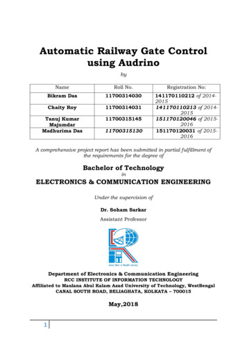
4.1 Circuit Diagram Of prototypeFig 12. Circuit diagram of prototype4.2 Working PrincipleThe working principle of the prototype is quite simple.Two IR sensors are placed at the bpthsides of railway crossing.They are placed 1Km. apart from level crossing.The arrival anddeparture of train is sensed by the sensors and transmitted to the audrino uno.There’s a loop that keeps running in the audrino that always checks the ir sensor output.Ifthe ir sensor outputs the signal ,the audrino instructs the L293D to close the gate usingStepper motor and play the buzzers to alert the road users.The stepper motor exactly rotatedat 90 degrees and the railway gate gets closed.After passing the train the departure is sensedby the another IR sensor which is placed at the opposite side of the other other IRsensor.When the departure is sensed by the another IR sensor the audrino gets theacknowledgement signal to open the gate via L293D module.Same process happens if the train is coming from another side.The delay between sensedsignal and closing of gate is kept small here(500 ms).But in real ife the delay is kept more.5.1 Possible obstaclesThough this prototype is simple to build and highly reliable but there’re some obstacles too.Rather than a train if an animal or other object is placed in front of the IR sensor the alarmwill and the gate will be closed which is not desirable at all.Also other natural obstacles likefog may arise problems.27
There’re also a scope of alerting the nearest railway station about arrival and departure ofthe train.5.2 Possible solutions and future scopesThe problems indicated above can be overcome by adding some extra modules.Like we left the GSM module for future scope.After addingh this module,upon arrival anddeparture of train,the GSM module will send an SMS to registered phone number foracknowledgement and safety.Also adding a pair of pressure sensor increases the chance of fault triggering of gate as wellas alarm. After adding the pressure sensor , the audrino closes the gate after reciving bothsignal from IR sensor as well as pressure sensor.28
THE END29
means one in Italian and was chosen to mark the release of Arduino Software (IDE) 1.0.The Uno board and version 1.0 of Arduino Software (IDE) were the reference versions of Arduino, now evolved to newer releases. The Uno board is the first in a series of USB Arduino boards, and the reference model for th