Transcription
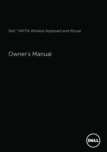
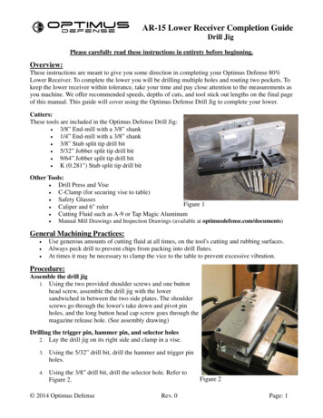
AR-15 Lower Receiver Completion GuideDrill JigPlease carefully read these instructions in entirety before beginning.Overview:These instructions are meant to give you some direction in completing your Optimus Defense 80%Lower Receiver. To complete the lower you will be drilling multiple holes and routing two pockets. Tokeep the lower receiver within tolerance, take your time and pay close attention to the measurements asyou machine. We offer recommended speeds, depths of cuts, and tool stick out lengths on the final pageof this manual. This guide will cover using the Optimus Defense Drill Jig to complete your lower.Cutters:These tools are included in the Optimus Defense Drill Jig: 3/8” End-mill with a 3/8” shank 1/4” End-mill with a 3/8” shank 3/8” Stub split tip drill bit 5/32” Jobber split tip drill bit 9/64” Jobber split tip drill bit K (0.281") Stub split tip drill bitOther Tools: Drill Press and Vise C-Clamp (for securing vise to table) Safety GlassesFigure 1 Caliper and 6" ruler Cutting Fluid such as A-9 or Tap Magic Aluminum Manual Mill Drawings and Inspection Drawings (available at optimusdefense.com/documents)General Machining Practices: Use generous amounts of cutting fluid at all times, on the tool's cutting and rubbing surfaces.Always peck drill to prevent chips from packing into drill flutes.At times it may be necessary to clamp the vice to the table to prevent excessive vibration.Procedure:Assemble the drill jig1. Using the two provided shoulder screws and one buttonhead screw, assemble the drill jig with the lowersandwiched in between the two side plates. The shoulderscrews go through the lower's take down and pivot pinholes, and the long button head cap screw goes through themagazine release hole. (See assembly drawing)Drilling the trigger pin, hammer pin, and selector holes2. Lay the drill jig on its right side and clamp in a vise.3.Using the 5/32” drill bit, drill the hammer and trigger pinholes.4.Using the 3/8” drill bit, drill the selector hole. Refer toFigure 2. 2014 Optimus DefenseRev. 0Figure 2Page: 1
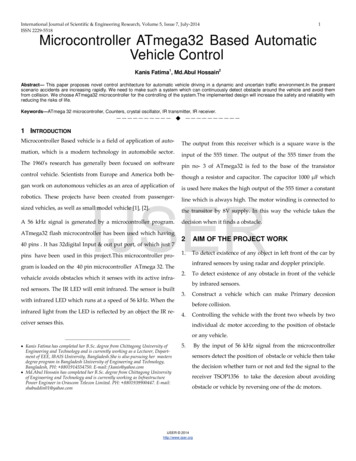
AR-15 Lower Receiver Completion GuideDrill JigFire Control Pocket5. Stand the drill jig upright and clamp it in the vise. Fasten the Fire Control Pocket Top Plate tothe drill jig in the "drilling position" (array of drilled holes closer to the buffer tube ear).Note: the top plate and the left side plate have circular notches that align. This is where you will set drilling depth and finalrouting dept.Figure 36.Set the 9/64” drill bit tool final depth using theexposed circular notch. See Figure 3.7.Using the 9/64” drill bit, drill each of the 32 holes.8.Remove the Fire Control Pocket Top Plate from thedrill jig. Load the 3/8” drill bit and set the finaldrilling depth using the same circular notch as instep 6.9.Using the 3/8” drill bit, drill the holes marked inFigure 4, effectively removing most of the materialfrom the fire control pocket. Figure 5 shows most ofthe fire control pocket 3/8" drilled out.10. Re-attach the FireControl Pocket TopPlate with the routingpocket located over thefire control pocket area.See Figure 6.11. Load the 3/8” end-milland set the final tooldepth using the samenotch as in step 6.3/8" drill the 14holes shown in blueFigure 4Figure 512. Route out the fire control pocket using the top plate'srouting pocket as a guide. The first depth of cut must be1.375” /-.03" below the top plate's top face, so that theflutes (cutting edges) of the end-mill does not cut in tothe top plate. Move the cutter around the routing guide ina clockwise direction (conventional milling direction).Warning: If the first depth (1.375") is not set correctly, the Fire ControlPocket Top Plate will be damaged.Figure 6 2014 Optimus Defense13. Route next depths about 1/4" to 3/8" deeper until finaldepth is reached.Rev. 0Page: 2
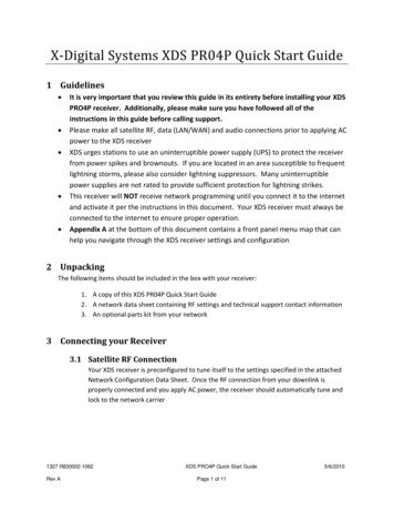
AR-15 Lower Receiver Completion GuideDrill JigTrigger Slot14. Remove the Fire Control Pocket Top Plate and fastenthe Trigger Slot Top Plate to the drill jig in the"drilling position".Note: The top plate now aligns with a different circular slot for drillingand final routing depth.15. Load the letter K (dia. 0.281") drill bit and set the finaldrilling depth using the exposed circular notch. Beforeturning the drill press spindle ON, lower the drill bitthrough one of the holes until it is just above the floorof the fire control pocket. Then turn ON the drill pressFigure 7spindle and drill the hole. Repeat for all three holesthrough the floor of the fire control pocket.Warning: If the K drill bit flutes (cutting edges) touch the Trigger Slot Top Plate while the drill is spinning, the drill bit will"grab" and damage the top plate.16. Rotate the Trigger Slot Top Plate so that the routing pocket is above the drilled holes. SeeFigure 8.17. Load the 1/4" end-mill and set the final millingdepth as before in Step 15.18. Route out the trigger slot using the routing pocketas a guide. Move the cutter around the pocket in aclockwise direction (conventional millingdirection).Note: The Trigger Slot Top Plate routing pocket is design for a 1/4"end-mill with a 3/8" shank.Figure 819. After machining both pockets take somemeasurements and compare it to the inspection drawing. All dimensions should be within thetolerance noted on the drawing. If out of tolerance, carefully consider how it will affect thefunction of your lower.De-burr20. Using a suitable de-burr tool or sandpaper, carefully take down any sharp edges.Warning: Once you have machined any of the hammer, trigger and selector holes or the fire control pocket and trigger slot,you have what is considered to be a firearm. This firearm cannot be traded, gifted or sold without the assistance of a FFL.Optimus Defense assumes no liability for the actions of the user of this product. You are responsible for knowing all lawsand regulations in your area relating to this product. We are not lawyers, and this is not legal advice 2014 Optimus DefenseRev. 0Page: 3
AR-15 Lower Receiver Completion GuideDrill JigRecommended Cutting Parameters:3/8” End-millSpeed: 2050 RPMStick Out: 2”First Depth of Cut: 1.375” (below top plate's top)Next Depth of Cut: 0.375” deeper or lessK Drill (dia. 0.281")Speed: 2700 RPMStick Out: 2”1/4” End-millSpeed: 3050 RPMStick Out: 2”Definitions3/8” DrillSpeed: 2000 RPMStick Out: 2”Peck Drill: 0.190”5/32” DrillSpeed: 4800 RPMStick Out: 2”Peck Drill: 0.080”9/64” DrillSpeed: 5450 RPMStick Out: 2”Peck Drill: .070”Calculations:RPM – Revolutions per MinuteSFM – Surface Feet per MinuteDia. – Diameter of cutterFormulasRPM SFM * 3.82 / Dia.SFM for High Speed Steel cutting Aluminum is200. (conservative cutting)Recommended RPMs are based off the abovecalculation. You can use a slower RPM andcompensate by lowering your feed rate as well.Other Information:Climb vs. Conventional Milling:Conventional milling is recommended for manual machining since itkeeps pressure against the table of the mill. For the fire control pocket,it is recommended to machine in a conventional pattern. This isgenerally moving the cutter clockwise around the inside of the pocket.Tool Chatter:Tool chatter may occur due to the long length of these cutters. If youare experiencing excessive chatter or getting a bad surface finish,reduce the spindle RPM and use more cutting fluid.Cutting Fluid:Using a cutting fluid that is made for machining aluminum, such as A9 or Tap Magic Aluminum, will greatly improve the machining finish, reduce tool chatter, and improvetool life.Warning: Manual machining can be dangerous. You should know how to safely operate the tools and equipment beforeattempting to complete an AR-15 Lower Receiver. Always were safety glasses. This Guide is for informational andeducational purposes only. Optimus Defense is not liable for an property damage, personal injury, or death, as a result ofusing this Guide. 2014 Optimus DefenseRev. 0Page: 4
REVISIONSREVBYDATEAPPR. BYDESCRIPTION2X Flat Head 10-24 x 3/4"Trigger Slot Top PlateFire Control PocketTop Plate4X Flat Head10-24 x 1"Fire Control Pocket Top Plateinstalled in the "drilling position"Right Side PlateOptimusDefense80% LowerLeft Side Plate2X Shoulder Screw 10-24Trigger Slot Top Plateinstalled in theOptimus Defense3940 Broad St. Ste 7-329 SLO, CA 93401"drilling position"www.optimusdefense.comButton Head 10-24PROPRIETARYTHE INFORMATION CONTAINED INTHIS DRAWING IS THE SOLE PROPERTY OFOPTIMUS DEFENSE. ANY REPRODUCTIONIN PART OR AS A WHOLE WITHOUT THEWRITTEN PERMISSION OF OPTIMUSDEFENSE IS PROHIBITED.MATERIAL:TITLE:AR-15 Drill Jig G APPR.XXX00/00/00MFG APPR.XXX00/00/00UNLESS OTHERWISE SPECIFIED:XXXXFINISH:XXXXDIMENSIONS ARE IN INCHESTOLERANCES:FRACTIONS: 1/16.030.X.XX.015.XXX .005ANGULAR: .5INTERPRET GEOMETRIC TOLERANCINGPER: ANSI/ASME Y14.5-1994PROJECT:Drill JigSIZE:ASCALE:noneDWG. NO.XXXXXXSHEET:1OF1REV:-
per: ansi/asme y14.5-1994 mfg appr. xxx xxx 00/00/00 00/00/00 4/29/14 00/00/00 www.optimusdefense.com 1 title: ar-15 drill jig assembly-drill jig xxxxxx project: a none of 1 rev: xxxx by date defense is prohibited. by interpret geometric tolerancing material: date xxx angular: unless ot