Transcription
Geberit ns de montageIstruzioni per il montaggio
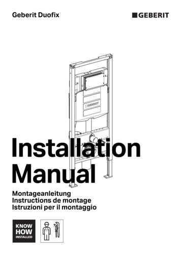
Masse Geberit Duofix Element für Wand-WC, 112 cm, mit Sigma Unterputzspülkasten 12 cm19¾"(500)4¾"(120)Product 0Product SpecificationsGeberit Model No. / Flush volume: 111.335.00.5 / 1.6/0.8 gpf (6.0/3.0 lpf) 111.902.00.5 / 1.28/0.8 gpf (4.8/3.0 lpf)71/8"–9"(180–230)2"4"(100) (50)2"(50)For Geberit actuator plates Sigma.To achieve the specified flush volume, thewashdown WC for single or dual flush from a thirdparty supplier must be ANSI-listed.Approved for use in the US and Canada (cUPC )Properties Square structural 16 gauge powder coatedsteel frame Carrier height adjustable range 15" (381) to 19"(483) bowl rim height Shockproof concealed tank, fully insulatedagainst condensation, made of high-densitypolyethylene (HDPE). Anti-siphon fill valve meets ANSI / ASSE1002-99 05–407)Concealed tank and bowl carrier, wall-hung twohole toilet bowl and actuator plate.Tank and carrier system shall fit within a minimum 53/4" (150) deep wall with studs placed 19 3/4" (500)apart, water supply shall be 1/2" copper, minimumwater pressure 35 PSI. The bowl shall be an IAMPOlisted wall-hung bowl to match flush volumesshown in table. The carrier shall have adjustableheight for 15" (381) to 19" (483) bowl rim height.26⅜"(670)Finishd Rim Height (FRH)FRH X plus 3"FF7¾"(195)min 4"(100)FRHStud FrontCenter Pipe3½"–5³ ₁₆"(90–135) POOFDUJPO PG XBTUF PVUMFU UP ESBJO QJQF6XSSOLHG ILWWLQJ LV '3( DQG FDQQRW EH JOXHG 1RWH 6XSSOLHG FRXSOLQJ FRQQHFWV WR ß SODVWLF GUDLQDJHSLSHV RQO\ 7R FRQQHFW VXSSOLHG ZDVW EHQG WR RWKHU PDWHULDOV SXUFKDVH DOWHUQDWH FRXSOLQJ ZLWK RQH HQG IRU ß SODVWLF Material DeterminationRecommended material for wall surfaceconstruction: Gypsum / green boardCement boardTile backer boardCeramic tile surfaceWall thickness not to exceed 3"WarrantyLimited lifetime warranty on tank and carrier.996.506.00.010 year warranty on fill valve and flush valve.One year warranty on actuator plate.996.506.00.02 03-2021968.074.00.0(01)
2Installation996.506.00.0MontageregelnInstallation RequirementsTo install tank and carrier, a 2 x 6" wood frame ormetal frame construction is required. Studs mustbe placed 19 3/4" apart (clearance) where carrierwill be positioned inside the wall.Bowl Finished Rim Height (FRH)3Remove carrier and installation hardware from itsbox. Determine FRH for wall-hung bowl and adjustcarrier height in accordance with requirement.Dimensions can be taken from bowl or carrierspecification sheet. Be sure to allow for finishedfloor and sole plate height.AB996.506.00.0Discharge elbow installationC3½"–4¾"(90–120)D3¹ ₈"–5³ 3/16"(105-135)4 03-2021968.074.00.0(01)3
Tank and carrier installation123456"19 ¾Locate carrier supporting studs andreinforce with additional nails. Ensurerough-in for the carrier is plumb and square.Wall framework must be affixed to the floorand ceiling for maximum support.Position carrier unit in the prepared opening.Carrier face plate must be flush with thefront of the surrounding studs so thatmaximum support for the wall sheeting(applied later) will be accomplished. Withcarrier still in place, mark all anchor and bolthole locations on sole plate and studs. Marklocation for the 3" DWV discharge pipe.C⁵ ₁₆"1"47"–5⁵ ₁₆"6"12"–1Pull out carrier from framework and drill six(6) pilot holes (3/16") for the supplied lagscrews where marked on sole plate. Alsodrill six (6) bolt holes (5/16") where markedon both studs. Use hole saw and bore a 4"hole through sole plate and floor for thedischarge stop out pipe.F.F.Install 3" DWV waste pipe through floor andconnect to waste line (i.e. PVC, copper, castiron).ASet carrier unit back into frameworkand bolt in place with hardware provided.BConnect waste outlet to drain pipe.Supplied fitting is HDPE and cannot be glued.Note: Supplied coupling connects to 3" plasticdrainage only!To connect supplied waste bend to othermaterials, purchase alternate coupling, with oneend for 3" plastic.DABCDInstall ½" rods with plastic sleeves,pipe plugs andmud guard during the rough-in installationComplete waste elbow connectionFor finishing the installation of bowl andactuator plate see detailed instructions.0 7445 40 5 Install two (2) 1/2" x 6" fixture support rodswith plastic sleeves (A), yellow pipe caps (B)and mud guard (C) for protection during wallsurface construction. 03-2021968.074.00.0(01)
Water supply installation14R ½''2R ½''53NPT 1/2" elbow 03-2021968.074.00.0(01)5
8ationInstall lManua996.108.00.0 (00)6itungMontageanle montagedeInstructions il montaggioperIstruzioni91Install wall surface material such as highdensity Gypsum / green Board, CementBoard, Tile Backer Board with optionalceramic tile finish surface as the mostsuitable materials. Provide cut outs for theprotruding parts like inlet and outlet pipesand the rectangular access box.276 03-2021968.074.00.0(01)
Bowl installation14Remove yellow protection plugs and sealsfrom pipes.Add dimension X and 1/8". Using thatdimension, mark a line on the pipemeasuring from the hub side. Cut off thepipe at the line with a pipe cutter.1 1/8" (3 mm)252Insert discharge pipe into the pipe hub in thewall. Place a straight edge flush against thewall and mark a line on the pipe. Fit finnedrubber seal onto flush pipe. Repeat sameprocedure for discharge pipe.XXAdd dimension Y and 1/8". Using thatdimension, mark a line on the pipemeasuring from the hub side. Cut off thepipe at the line with a pipe cutter.21 1/8" (3 mm)YY2621Bevel the sharp edges as shown to assure asmooth insertion into the pipe hubs in thewall.13Place discharge pipe with gasket into wasteoutlet of bowl. Also place flush pipe with fingasket into inlet of bowl. Then mark asecond line on both pipes.2712Install both seals into the pipes in the wall.Lubricate seals with appropriate rubber seallubricant.1 03-2021968.074.00.0(01)7
8Remove protective sleeves from mountingrods. Determine protruding rod length forbowl installation. Install both pipes into thehubs in the wall.AA21 13/16" (20 mm)2CAUTIONHigh torque forcesWC ceramic appliance may break Do not overtighten hex nuts.9Place bowl onto rods. Attach cap washerwith nose up and facing forwards onto rods.Install washer and hex nuts, tighten loosely.Level bowl. Tighten hex nuts. Snap on thebolt caps.10Seal gap around bowl with waterproofsealant.Sound insulation pad is optional or required.12ContactGeberit2100 Clearwater Drive, Des Plaines, IL 60018-5999Phone: (847) 803 5000 Fax: 847/803-5454For Technical Assistance: 800 / TEC-TRUE (800-832-8783) www.geberit.us2Geberit International AG, Schachenstrasse 77, CH-8645 JonaT 41 55 221 63 00F 41 55 221 63 16documentation@geberit.com www.geberit.com8 03-2021968.074.00.0(01)
rough-in for the carrier is plumb and square. Wall framework must be affixed to the floor and ceiling for maximum support. 2 Position carrier unit in the prepared opening. Carrier face plate must be flush with the front of the surrounding studs so that maximum support for the