Transcription
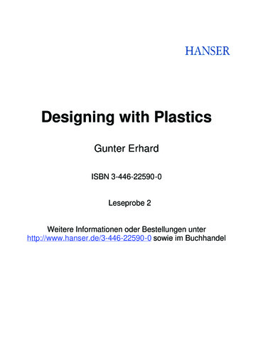
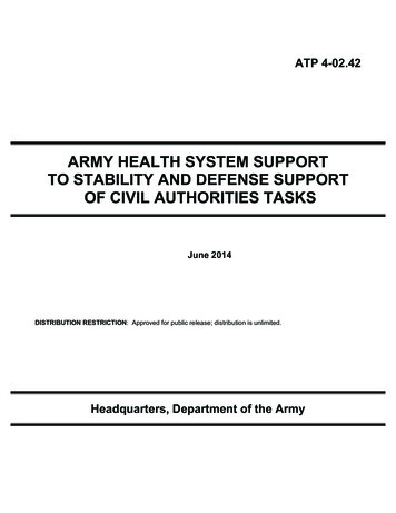
LANL Engineering Standards Manual ISD 341-2Section WFP 2-01 – Welding Fabrication ProcedureChapter 13, Welding & JoiningRev. 1, 10/27/06Attachment 3, ASME B31.8, Gas Transmission & Distribution Piping Alignment and Acceptance Criteria1.0JOINT FIT-UP AND ALIGNMENT1.1For piping systems that operate at hoop stress of less than 20% and the internal adjoiningends do not vary more than 1/8 in. and adequate penetration and fusion can be obtained nospecial treatment is necessary. If the offset is greater than 1/8 in. the following shall apply.1.2For piping systems that operate at hoop stress of 20% or more of the Specified MinimumYield Strength the following shall apply.1.2.1If the internal adjoining ends do not vary more than 3/32 in. and adequatepenetration and fusion can be obtained no special treatment is necessary. SeeFigure 14 of this Attachment.1.2.2Where the nominal internal offset is greater than 3/32 in. and no access to the insidefor welding, a transition shall be made to the thicker section not to exceed 30º (3:1taper) or less than 15º (1 ½:1 taper). See Figure 15 of this Attachment.1.2.3Where the nominal internal offset is greater than 3/32 in. but does not exceed ½ thethinner section and there is access to the inside for welding, the transition may bemade with a tapered weld or transition as described in paragraph 9.2.2 shall beperformed. See Figure 15 of this Attachment.1.2.4Where the nominal internal offset is more than ½ the thinner section and there isaccess for welding, the transition may be made with taper cut or by a combinationtaper weld to ½ the thinner section see Figure 15 and taper cut from that point asshown in Figure 15 of Attachment.1.3Where the external offset does not exceed ½ t of the thinner section, the transition may bemade by welding as shown by Figure 15 of this Attachment, provided the angle of the riseof the weld surface does not exceed 30º (3:1 taper) and both bevel edges are properlyfused. Where the is an external offset exceeding ½ the thinner section, that portion of theoffset over ½ t shall be tapered as shown in Figure 15 of this Attachment.1.4The root opening and fit-up tolerances shall be as specified in the weld joint design in thisAttachment as applicable. If the tolerances cannot be achieved, the end preparations maybe built up by welding (with an approved WPS or WTS) or re-prepped by machining orgrinding.1.5Parts to be joined by a tee or fillet weld shall be brought into as close contact as ispracticable. The maximum gap between these parts shall not exceed 1/8 in. If theseparation is greater than 1/16 in., each leg of the fillet weld shall be increased by theamount of separation.Page 1 of 8
LANL Engineering Standards Manual ISD 341-2Section WFP 2-01 – Welding Fabrication ProcedureChapter 13, Welding & JoiningRev. 1, 10/27/06Attachment 3, ASME B31.8, Gas Transmission & Distribution Piping Alignment and Acceptance Criteria1.62.0In assembly of socket weld joints, the pipe or tube shall be withdrawn a distance ofapproximately 1/16 in. away from contact between the end of the pipe and the face of theshoulder of the socket. In sleeve-type joints without an internal shoulder, there shall be adistance of approximately 1/16 in. between the butting ends of the pipe or tube and thebutting ends shall be centered in the sleeve. Note: Gap inserts (Gapalets or equivalent)and approved shims may be used with prior approval from the design engineer or LANLWelding Program Administrator.ACCEPTANCE CRITERIA FOR COMPLETED WELDS2.1Butt Welds2.1.1The quality of welding shall be checked visually on a sampling basis (seeparagraph 2.1.3) and defective welds shall be removed and replaced or repaired inaccordance with the original WPS or WTS as applicable2.1.2The quality of welds shall also be examined by nondestructive examination (NDE)methods. The NDE method may consist of radiography, magnetic particle or anyother acceptable NDE method.2.1.3The following is the minimum number of welds that shall be selected on a randombasis from each day’s production. Each weld shall be examined visually andaccepted prior to being examined by an NDE method. Each weld selected shall beexamined for the entire circumference. If only part of the weld circumference is tobe examined, the responsible engineer or LANL WPA shall approve the selectionprocess prior to its implementation. The same criteria shall be applied to pipingsystems double ending at railheads or yards. 10% of welds in Location Class 1 15% of welds in Location Class 2 40% of welds in Location Class 3 75% of welds in Location Class 4 100% of welds in compressor stations, and at major or navigableriver crossings, major highway crossings and railroad crossings, ifpractical, but in any case not less than 90%. All tie-in welds notsubjected to a positive pressure proof test shall be examined.See page 9 for pipe system classification criteria.2.1.4Welds that are examined visually shall meet the visual acceptance standards of API1104. See WFP 2-03, Welding Fabrication Procedure for API 1104 Welding ofPipelines and Related Facilities section of this program. The results of visualexamination shall be used to control the quality of the welding.Page 2 of 8
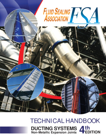
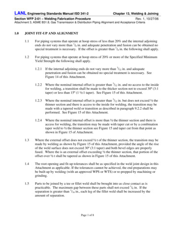
LANL Engineering Standards Manual ISD 341-2Section WFP 2-01 – Welding Fabrication ProcedureChapter 13, Welding & JoiningRev. 1, 10/27/06Attachment 3, ASME B31.8, Gas Transmission & Distribution Piping Alignment and Acceptance Criteria2.1.5When radiography or other NDE methods are employed, the procedure shall meetthe requirements of API 1104.2.1.6When the pipe size is less NPS 6 or the project involves a limited number of weldsthat NDE examination would be impractical, and the system is intended to operateat 40% or less of specified yield strength, then provisions of paragraphs 2.12, 2.13,and 2.1.5 are not mandatory, provided the welding is examined visually by aqualified (AWS CWI or equivalent) inspector.2.1.7In addition to the NDE requirements qualified (AWS CWI or equivalent) weldinspection personnel continually (surveillance basis) control the quality of the inprocess welding.2.1.8As-welded surfaces are permitted; however, the surface of welds shall besufficiently free from coarse ripples, grooves, overlaps, abrupt ridges, and valleys.2.1.9The surface condition of the finished welds shall be suitable for the properinterpretation of radiographic and other nondestructive examinations whennondestructive examinations are required. Surface preparation, when required forRT, PT, MT, or UT shall have a minimum of a 250 RMS or equivalent finish.2.1.10 In those cases where there is a question regarding the surface condition on theradiographic film, the film shall be compared (overlay) to the actual weld surfacefor interpretation and determination of acceptability.2.2Socket and Fillet Welds2.2.1As-welded surfaces are permitted; however, the surface of welds shall besufficiently free from coarse ripples, grooves, overlaps, abrupt ridges, and valleys.2.2.2The surface condition of finished socket and fillet welds shall be suitable for theproper interpretation of nondestructive examinations, where required. Surfacepreparation, when required for PT, MT, or UT shall have a minimum of a 250 RMSor equivalent finish.2.2.3Socket and fillet welds may vary from convex to concave. The size of a fillet weldis determined as shown in the Figure 12. Typical minimum fillet weld details forslip-on flanges and socket-welding components are also contained in Figure 16 ofthis Attachment.Page 3 of 8
LANL Engineering Standards Manual ISD 341-2Chapter 13, Welding & JoiningSection WFP 2-01 – Welding Fabrication ProcedureRev. 1, 10/27/06Attachment 3, ASME B31.8, Gas Transmission & Distribution Piping Alignment and Acceptance CriteriaFigure 12FILLET WELD PROFILES AND DIMENSIONSPage 4 of 8
LANL Engineering Standards Manual ISD 341-2Chapter 13, Welding & JoiningSection WFP 2-01 – Welding Fabrication ProcedureRev. 1, 10/27/06Attachment 3, ASME B31.8, Gas Transmission & Distribution Piping Alignment and Acceptance CriteriaFigure 14PREPARATION FOR BUTT WELDINGPage 5 of 8
LANL Engineering Standards Manual ISD 341-2Chapter 13, Welding & JoiningSection WFP 2-01 – Welding Fabrication ProcedureRev. 1, 10/27/06Attachment 3, ASME B31.8, Gas Transmission & Distribution Piping Alignment and Acceptance CriteriaFigure 15Acceptable Design for Unequal Wall ThicknessPage 6 of 8
LANL Engineering Standards Manual ISD 341-2Chapter 13, Welding & JoiningSection WFP 2-01 – Welding Fabrication ProcedureRev. 1, 10/27/06Attachment 3, ASME B31.8, Gas Transmission & Distribution Piping Alignment and Acceptance CriteriaFigure 16Recommended Attachment Details for FlangesPage 7 of 8
LANL Engineering Standards Manual ISD 341-2Chapter 13, Welding & JoiningSection WFP 2-01 – Welding Fabrication ProcedureRev. 1, 10/27/06Attachment 3, ASME B31.8, Gas Transmission & Distribution Piping Alignment and Acceptance CriteriaASME B31.8 SYSTEM CLASS CRITERIALocation Class 1 – A Location Class 1 is any 1 mile (1.6 km) section that has 10 or fewer buildingsintended for human occupancy. A Location Class 1 is intended to reflect areas such aswasteland, deserts, mountains, grazing land, farmland, and sparsely populated areas.a. Class 1 Division 1 – A Location Class 1 where the design factor of the pipe is greater than0.72 but equal to or less than 0.80, and which has been hydrostatically tested to 1.25 times themaximum operating pressure. See Table 841.114B of ASME B31.8 for exceptions to thedesign factor.b. Class 1 Division 2 - A Location Class 1 where the design factor of the pipe is equal to or lessthan 0.72 but equal to or less than 0.80, and which has been hydrostatically tested to 1.1 timesthe maximum operating pressure. See Table 841.114B of ASME B31.8 for exceptions to thedesign factor.Location Class 2 - A Location Class 2 is any 1 mile (1.6 km) section that has more than 10 but fewer than46 buildings intended for human occupancy. A Location Class 2 is intended to reflect areaswhere the degree of population is intermediate between Location Class 1 and Location Class 3such as fringe areas around cities and towns, industrial areas, ranch or country estates, etc.Location Class 3 - A Location Class 3 is any 1 mile (1.6 km) section that has 46 or more buildingsintended for human occupancy except when a Location Class 4 prevails. A Location Class 3 isintended to reflect areas such as suburban housing developments, shopping centers, residentialareas, industrial areas, and other populated areas not meeting Location Class 4 requirements.Location Class 4 – Location Class 4 includes areas where multi-story buildings are prevalent, and wheretraffic is heavy or dense and where there may be numerous other utilities underground.Multistory means 4 or more floors above ground including the first or ground floor. The depthof basements or number of basement floors is immaterial.Page 8 of 8
Section WFP 2-01 – Welding Fabrication Procedure Rev. 1, 10/27/06 Attachment 3, ASME B31.8, Gas Transmission & Distribution Piping Alignment and Acceptance Criteria 1.0 JOINT FIT-UP AND ALIGNMENT 1.1 For piping systems that operate a