Transcription
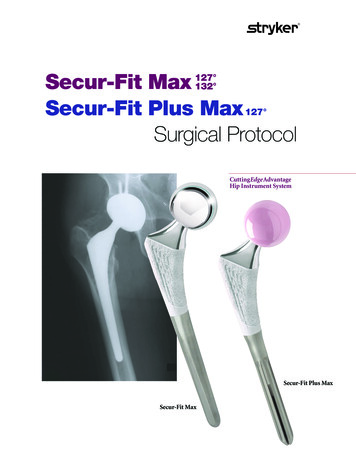
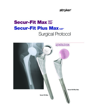
1522 09 LSP47M Rev2 Secur Fit Max SP 9678 SecurFit SP 4/27/10 1:48 PM Page 1Secur-Fit Max 127 132 Secur-Fit Plus Max 127 Surgical ProtocolCuttingEdge AdvantageHip Instrument SystemSecur-Fit Plus MaxSecur-Fit Max
1522 09 LSP47M Rev2 Secur Fit Max SP 9678 SecurFit SP 4/27/10 1:48 PM Page 2CuttingEdgeAdvantageHip Instrument SystemSecur-Fit MaxSecur-Fit Plus MaxSurgical ProtocolTable of ContentsStep 1 – Pre-Operative Planningand X-Ray Templating.1Step 2 – Neck Resection .2Optional Step – Box Chisel .2Step 3 – Opening the Femoral Canal:Axial Starter Reamer .2Step 4 – Trochanteric Reaming .2Step 5 – Tapered Reaming .3Cylindrical Reaming .3Step 6 – Broaching the Femur .3Optional Step – Calcar Planer .3Step 7 – Trial Reduction .4Step 8 – Femoral Stem Insertion .5Step 9 – Head Assembly .5Catalog Information .6Indications Non-inflammatory degenerative joint disease, including osteoarthritis and avascular necrosis;Rheumatoid arthritis;Correction of functional deformity;Revision procedures where other treatments or devices have failed; and,Treatment of nonunions, femoral neck fractures, and trochanteric fractures of the proximalfemur with head involvement that are unmanageable using other techniquesContraindications Active infection or suspected latent infection in or about the hip joint;Bone stock that is inadequate for support or fixation of the prosthesis;Skeletal immaturity;Any mental or neuromuscular disorder that would create an unacceptable risk of prosthesisinstability, prosthesis fixation failure, or complications in post-operative care.Warnings and PrecautionsSee package insert for warnings, precautions, adverse effects and other essential productinformation.1IntroductionThe CuttingEdge Advantage Instrument System is versatile, offering surgeons great flexibilityand ease of use in approaching the implantation of the Secur-Fit Max and Secur-Fit Plus MaxFemoral Components. Each surgeon should use the surgical approach for total hip arthroplastywith which he/she is most familiar. Patient positioning, preparation and draping, skin incision,soft tissue dissection and hip dislocation should be performed according to the surgeon’spreferred technique, making certain to adequately expose the acetabulum and the proximal femur.1Pre-Operative Planning and X-Ray TemplatingPre-operative planning aids in the selection of the appropriate implant style and size forthe patient's hip pathology. Optimal femoral stem fit, prosthetic neck length, and neckoffset/angle should be evaluated during pre-operative X-Ray analysis using providedtemplates (Figure 1). The appropriate proximal body and stem length should beassessed in the A/P view. Anatomic anomalies that could prevent the intra-operativeachievement of the established pre-operative goals may also be detected through suchplanning. If needed, a lateral view may be taken to assess the femoral canal curvature.This publication sets forth detailed recommended procedures for using Stryker Orthopaedics devices and instruments. It offers guidance that you should heed,but, as with any such technical guide, each surgeon must consider the particular needs of each patient and make appropriate adjustments when and as required.1
1522 09 LSP47M Rev2 Secur Fit Max SP 9678 SecurFit SP 4/27/10 1:49 PM Page 32Neck Resection2AA proper neck resection level directly affects stem fit and placement.The resection should be made at a level determined duringtemplating to restore proximal femoral head/neck length andoffset. Using anatomic landmarks identified during templating,the Neck Resection Guide may be utilized for proper resectiondetermination. The Neck Resection Guide is identical in profileto a Secur-Fit Max size #7 implant body, thus providing a meansof simulating stem alignment. Care should be taken to align theaxis line of the Neck Resection Guide to the center axis of thefemoral shaft; the scales on the lateral flange or medial radius ofthe guide can be used to reference the greater or lesser trochanterrespectively when making the final cut (Figure 2A).Optional StepBox Chisel2BThe Box Chisel removes bone from the proximal lateralportion of the resected femoral neck to allow access to thefemoral medullary canal (Figure 2B).3Opening the Femoral Canal: Axial Starter Reamer3Depth GaugeGroovesThe Axial Starter Reamer is used to enter the femoralmedullary canal through the trochanteric fossa. The StarterReamer has a trochar point to facilitate entry. It should beinserted to a depth such that the distal tip of the StarterReamer is 1cm below the distal end of the final size broach.The groove, on the Starter Reamer shaft, is approximately inline with the intersection point of the femoral axis of thefemur and the neck resection line (Figure 3).Trochar Point4Trochanteric Reaming4Insert the Trochanteric Reamer into the proximal area of thecanal and bias the cutting teeth laterally to remove the desiredamount of bone (Figure 4). Do not sink the reamer below thelevel of the trochanter. Performing this step can help facilitatethe axial alignment of the broach so that it is not pushed intovarus by an overhanging trochanter. Varus positioning of theimplant may result in an improperly placed or potentiallyundersized implant.2
1522 09 LSP47M Rev2 Secur Fit Max SP 9678 SecurFit SP 4/27/10 1:49 PM Page 45Tapered Reaming5A5BStarting one or two sizes smaller than the templated size, insertthe reamers into the canal such that the most proximal levelsof the cutting flutes are 1-2mm below the desired or templatedfemoral neck resection level. Ream sequentially upward in sizeuntil the last Tapered Reamer achieves good contact with thecortical bone (Figure 5A).Note: Though the fully toothed broaches may facilitatepreparation of the femoral implant without the use of taperedreamers, a narrow/tight diaphyseal shaft (e.g. champagne flutefemur) may result in broach resistance in the distal canal. Ifresistance is encountered, tapered reaming is recommended tominimize potential for distal femoral fractures. The option toskip any reaming step is at the discretion of the surgeon.Note: Tapered and Cylindrical Reamers are not found in thePrimary Instrument Tray and must be ordered separately.Reference page 6 for Tapered and Cylindrical Reaming ProductCode information.Cylindrical Reaming (for Secur-Fit Plus Max only)Cylindrically reaming prepares the femoral canal to fit withthe distal portion of the Secur-Fit Plus Max prosthesis.If a Secur-Fit Plus Max stem is selected, the size of the cylindrical portion of the stem is determined from pre-operativetemplating and is confirmed intra-operatively or by X-Ray.It is important to position the reamer laterally so that it isnot pushed into varus by an overhanging trochanter.Cylindrical reaming proceeds in 0.5mm increments untilendosteal contact is achieved. A choice can be madeintra-operatively to under-ream by 0.5mm or to reamline-to-line with the chosen implant size depending uponsurgeon preference and/or bone quality. To ensure distalpress-fit, under-ream by 0.5mm compared to the chosenimplant size. When reaming line-to-line with chosenimplant size, there is a potential that the distal flutes maynot fully engage with the bone.The Cylindrical Reamer is inserted such that the appropriate stem length marking intersects the most distal/medial point of the final neck resection level (Figure 5B).Reamers are marked in 10mm increments and should beinserted to a depth that matches or is 5mm deeper thanthe length of the chosen implant size (Table 1).6Table 1: Cylindrical Reamer Sizing(for Secur-Fit Plus Max only)StemSizeDistalDiameter (mm)Final CylindricalReamer (mm)Cylindrical ReamerMinimum Depth ofInsertion 315141615171618171918208.5 or 9.010.5 or 11.09.5 or 10.011.5 or 12.010.5 or 11.012.5 or 13.011.5 or 12.013.5 or 14.012.5 or 13.014.5 or 15.013.5 or 14.015.5 or 16.014.5 or 15.016.5 or 17.015.5 or 16.017.5 or 18.016.5 or 17.018.5 or 19.017.5 or 18.019.5 or 701701701701706ABroaching the FemurAssemble the Broach to the Broach Handle. Starting with thesmallest Broach, advance sequentially upward approaching thetemplated size until a stable snug-fit is obtained. Care should betaken to lateralize the proximal portion of the Broach in order tomaintain axial alignment of the Broach and implant (Figure 6A).Optional StepCalcar PlanerLeaving the final Broach seated in the femoral canal(Figure 6B), gently guide the Calcar Planer over the Broachpost (see note below) and initiate power prior to contactingthe femur. Slowly advance the Calcar Planer toward theBroach to plane the femur. Planing will continue until thepositive stop on the Planer contacts the Broach face.3
1522 09 LSP47M Rev2 Secur Fit Max SP 9678 SecurFit SP 4/27/10 1:49 PM Page 5Note: In the event that the Broach post is seatedcompletely below the resection plane (thus preventingengagement with the Calcar Planer), the Broach shouldbe removed and the resection re-cut at a slightly lowerlevel. The surgeon should then re-insert the final Broachensuring a stable and snug fit.6BCaution: Failure to operate the Calcar Planer inaccordance with the instructions above may result indamage to the femur.7Trial ReductionUsing the Broach, Trial Neck and Trial Head assembly, performa trial reduction to judge component positioning, leg length andhip stability (range of motion and laxity) before the final components are implanted. Select a CuttingEdge Advantage TrialNeck, 132 (Silver) or 127 (Gold), that has the same base necklength as the planned implant size (Table 2 and Figure 7A).7ATable 2: Broach and Neck Trial SizingStemSize132 NeckLength (mm)*127 NeckLength (mm)Broach Size B**Secur-Fit Plus Max is not available in 132 neck angle.**Available on Secur-Fit Plus Max only.Next, select the appropriate plastic C-Taper Trial Head.Refer to (Table 3) for head diameter and head offsetcombinations (Figure 7B).Trial Head OffsetsTable 3: Head Diameters and OffsetsC-Taper Trial Head Diameters22mm 26mm 28mm 32mm 36mm 40mm 44mm-5mmXXXX-3mmX-2.5mmXXXXXX0mmXXXXXXX 2.5mmXXXXXXX 5mmXXXXXXX 7.5mmXXXXXX 10mmXXXXXX7CHead offset is adjusted until leg lengths are equal. Jointstability can be checked by telescoping the leg and performinga full range of motion. If the hip is unstable or dislocates,either a 127 or 132 (Secur-Fit Max only) hip implant can beconsidered to achieve adequate offset. Upon confirmation ofthe selected components, remove the Trial Head and TrialNeck, and re-assemble the Broach Handle. Remove the Broachwith the help of the Slotted Mallet to preserve the integrity ofthe established cavity (Figure 7C).4
1522 09 LSP47M Rev2 Secur Fit Max SP 9678 SecurFit SP 4/27/10 1:49 PM Page 688Femoral Stem InsertionIntroduce the stem into the femoral canal axially with a manualforce until resistance is encountered. In order to assist in aligningand seating the stem, the threaded Femoral Impactor can beused. A Mallet is then used to seat the hip stem into the canal(Figure 8) until a stable snug-fit is attained. If instrumentimpingement on the greater trochanter is evident, the bullettipped Femoral Stem Impactor may be used. Surgeon Tip: Analternative is to insert by hand to within 1- 1.5cm and use theblunt nose to complete insertion.Caution: The surgeon should NOT attempt to continue impactingthe femoral component if visual and auditory clues indicate that theresting position of the femoral component has been reached. This istrue even if the femoral component is proud in reference to the level ofthe Broach Trial. Further impaction may result in fracture of the femur.99AHead AssemblyPrior to head assembly, neck length selection may be re-evaluatedusing a Stryker C-Taper Trial Head. Place the Trial Head ontothe stem neck taper and reduce the hip to verify that themechanics have not been altered due to implant seating.Remove the Trial Head and dry the implant trunnion with alaparatomy sponge or sterile towel.Select the appropriate corresponding C-Taper Femoral Head(CoCr, Alumina Ceramic, BIOLOX delta Ceramic) size andplace it onto the dry trunnion of the femoral stem with a slighttwist. Impact the head with two moderate blows using theStem Head Impactor (1104-1000) (Figure 9A).Note: See Trident Surgical Protocols for recommended headcompatibility.9BOptional Step9COptional StepOptional StepNote: When selecting a BIOLOX delta Universal Taper CeramicFemoral Head (6519-1-0xx) for implantation, use of a UniversalAdaptor Sleeve is necessary (Table 4).Table 4: Universal Adaptor SleevesUniversal Adaptor SleevePart NumberTaperStem MaterialCompatibility19-0XXXTC-TaperTMZF, Ti64, CoCrAfter completing the trialing process, intra-operativelyassemble the Adaptor Sleeve to the femoral stem manually.The Universal Adaptor Sleeve must be fully seated on thestem taper before the head is assembled (Figure 9B).Note: In no instance should any attempt be made topre-assemble the Adaptor Sleeve inside the BIOLOX deltaUniversal Ceramic head.Intra-operatively assemble the BIOLOX delta Universal TaperCeramic head onto the sleeved femoral stem and set with twomoderate blows using the Stem Head Impactor (1104-1000)(Figure 9C). Care must be taken to avoid excessive impactforces when assembling the Ceramic Head to the sleevedfemoral component.5
1522 09 LSP47M Rev2 Secur Fit Max SP 9678 SecurFit SP 4/27/10 1:49 PM Page 7Catalog InformationCuttingEdge Advantage General InstrumentsCatalog 100-1500Part Description127 C-Taper Trial Neck – 25mm127 C-Taper Trial Neck – 30mm127 C-Taper Trial Neck – 35mm127 C-Taper Trial Neck – 40mm132 C-Taper Trial Neck – 25mm132 C-Taper Trial Neck – 30mm132 C-Taper Trial Neck – 35mm132 C-Taper Trial Neck – 40mmC-Taper 22mm Trial Head 0mmC-Taper 22mm Trial Head 2.5mmC-Taper 22mm Trial Head 5mmC-Taper 22mm Trial Head 7.5mmC-Taper 22mm Trial Head 10mmC-Taper 26mm Trial Head -2.5mmC-Taper 26mm Trial Head 0mmC-Taper 26mm Trial Head 2.5mmC-Taper 26mm Trial Head 5mmC-Taper 26mm Trial Head 7.5mmC-Taper 26mm Trial Head 10mmC-Taper 28mm Trial Head -3.0mmC-Taper 28mm Trial Head -2.5mmC-Taper 28mm Trial Head 0mmC-Taper 28mm Trial Head 2.5mmC-Taper 28mm Trial Head 5mmC-Taper 28mm Trial Head 7.5mmC-Taper 28mm Trial Head 10mmC-Taper 32mm Trial Head -5mmC-Taper 32mm Trial Head -2.5mmC-Taper 32mm Trial Head 0mmC-Taper 32mm Trial Head 2.5mmC-Taper 32mm Trial Head 5mmC-Taper 32mm Trial Head 7.5mmC-Taper 32mm Trial Head 10mmC-Taper 36mm Trial Head -5mmC-Taper 36mm Trial Head -2.5mmC-Taper 36mm Trial Head 0mmC-Taper 36mm Trial Head 2.5mmC-Taper 36mm Trial Head 5mmC-Taper 36mm Trial Head 7.5mmC-Taper 36mm Trial Head 10mmC-Taper 40mm Trial Head -5mmC-Taper 40mm Trial Head -2.5mmC-Taper 40mm Trial Head 0mmC-Taper 40mm Trial Head 2.5mmC-Taper 40mm Trial Head 5mmC-Taper 40mm Trial Head 7.5mmC-Taper 40mm Trial Head 10mmC-Taper 44mm Trial Head -5mmC-Taper 44mm Trial Head -2.5mmC-Taper 44mm Trial Head 0mmC-Taper 44mm Trial Head 2.5mmC-Taper 44mm Trial Head 5mmCalcar PlanerFemoral Head ImpactorCuttingEdge Advantage Broach HandleSlotted MalletT-Handle - Trigger ReleaseT-Handle - Small Trigger ReleaseSmall Box ChiselMedium Box ChiselLarge Box ChiselCuttingEdge Advantage Neck Resection GuideCuttingEdge Advantage Primary InstrumentsCatalog 000Part DescriptionSecur-Fit/OmniFit EON Broach PF4Secur-Fit/OmniFit EON Broach PF5Secur-Fit/OmniFit EON Broach PF6/C4Secur-Fit/OmniFit EON Broach PF7/C5Secur-Fit/OmniFit EON Broach PF8/C6Secur-Fit/OmniFit EON Broach PF9/C7Secur-Fit/OmniFit EON Broach PF10/C8Secur-Fit/OmniFit EON Broach PF11/C9Secur-Fit/OmniFit EON Broach PF12/C10Secur-Fit/OmniFit EON Broach PF13/C11Secur-Fit/OmniFit EON Broach PF14/C12Small Trochanteric ReamerMedium Trochanteric ReamerLarge Trochanteric ReamerTapered Starter ReamerFemoral Stem ImpactorThreaded Femoral Stem Impactor/ExtractorOmniFit EON InserterOmniFit EON Locking InserterCanal Sizer Trial Tip (8mm)Canal Sizer Trial Tip (9mm)Canal Sizer Trial Tip (10mm)Canal Sizer Trial Tip (11mm)Canal Sizer Trial Tip (12mm)Canal Sizer Trial Tip (13mm)Canal Sizer Trial Tip (14mm)Canal Sizer Trial Tip (15mm)Canal Sizer Trial Tip (16mm)Canal Sizer Trial Tip (17mm)Canal Sizer Trial Tip (18mm)Canal Sizer Trial Tip (19mm)Canal Sizer Trial Tip (20mm)Depth Gauge HandleCuttingEdge Advantage Optional InstrumentsCatalog -1325S1100-1330S1100-1335S1100-1340SPart DescriptionSecur-Fit Max 127 C-Taper Trial Neck – 25mmSecur-Fit Max 127 C-Taper Trial Neck – 30mmSecur-Fit Max 127 C-Taper Trial Neck – 35mmSecur-Fit Max 127 C-Taper Trial Neck – 40mmSecur-Fit Max 132 C-Taper Trial Neck – 25mmSecur-Fit Max 132 C-Taper Trial Neck – 30mmSecur-Fit Max 132 C-Taper Trial Neck – 35mmSecur-Fit Max 132 C-Taper Trial Neck – 40mmCuttingEdge Advantage Instrument CasesCatalog 41100-1405Part DescriptionSingle Layer Outer CaseCuttingEdge Advantage General Instruments TrayCuttingEdge Advantage Primary Instruments TrayCuttingEdge Advantage Tapered Reamer TrayCylindrical Reamer Tray (8.0-14.5mm)Cylindrical Reamer Tray (15.0-20.0mm)Ancillary InstrumentsCatalog NumberHISH-3HISH-SHAFT1118-6000Part Description3lb. Slide Hammer HandleSlide ShaftHead Dis-assembly Instrument6
1522 09 LSP47M Rev2 Secur Fit Max SP 9678 SecurFit SP 4/27/10 1:49 PM Page 8Catalog InformationSecur-Fit Max Hip Stems127 Neck 120130140150160170170170Distal 0170170170170Distal 01211131214131514161517161817191820132 Neck 0#11#12#13#14Secur-Fit Plus Max Hip Stems127 Neck 10#11#11#12#12#13#13#14#14BaseNeck 5454325 Corporate DriveMah
This publication sets forth detailed recommended procedures for using Stryker Orthopaedics devices and instruments. It offers guidance that you should heed, but, as with any such technical guide, each surgeon must consider the particular needs of each patient and make appropriate adjustments when and as required. Secur-Fit Max Secur-Fit Plus MaxFile Size: 498KB