Transcription
2Anvil International, Piping & Pipe Hanger Design and Engineeringwww.anvilintl.com
PIPING and PIPE HANGERDESIGNandENGINEERINGW EIGHTSOFP IPING M ATERIALSL OAD C ALCULATION P ROBLEMThe material in this booklet has been compiled to furnish pipehanger engineers with the necessary data and procedures todetermine pipe hanger loads and thermal movements of thepipe at each hanger location.The tabulation of weights has been arranged for convenientselection of data that formerly consumed considerable time todevelop. In many instances this information was not availablefor general distribution. This made it necessary to developaverage or approximate weights that may be substituted withactual weights whenever practical.The "Hanger Load Calculation Problem" is typical of the actualsteps required in the solution of any pipe hanger installation.Great care was taken in collecting and printing data in thisbooklet to assure accuracy throughout. However, norepresentation or warranty of accuracy of the contents of thisbooklet is made by Anvil. The only warranties made by Anvilare those contained in sales contracts for design services orproducts.CONTENTS . PageDesign of Pipe Hangers . 4Determination of Hanger Locations . 4Hanger Load Calculations . 6Thermal Movement Calculations . 11Selection of the Proper Hangers . 13Typical Pipe Support Specification . 21Nuclear pipe Hangers . 24Seismic Supports . 24Supports for Grooved Piping . 27Application Examples . 30Weights of Piping Materials . 37Charts and Tables . 63Copyright 2003 Anvil International, North Kingstown, R.I.sales offices and warehouses on back coverwww.anvilintl.comAnvil International, Piping & Pipe Hanger Design and Engineering3
T HE D ESIGN O F P IPE H ANGERS I NTRODUCTIONTo avoid confusion, it is necessary to define the terms pipehanger and pipe support and clarify the difference betweenthe two. Pipe hangers are generally considered to be thosemetal elements which carry the weight from above with thesupporting members being mainly in tension. Pipe supportsare considered to be those elements which carry the weightfrom below with the supporting members being mainly incompression.It has become widely recognized that the selection and designof pipe hangers is an important part of the engineering studyof any modern steam generating or process installation.Problems of pipe design for high temperature, high pressureinstallations have become critical to a point where it isimperative that such aspects of design as the effect ofconcentrated hanger loads on building structure, pipe weightloads on equipment connections, and physical clearances ofthe hanger components with piping and structure be takeninto account at the early design stages of a project.Engineers specializing in the design of pipe hangers haveestablished efficient methods of performing the work requiredto arrive at appropriate hanger designs. However, theengineer who devotes varying portions of his time to thedesign of pipe hangers often must gather a considerableamount of reference data peculiar only to the hangercalculations for his current project.It is the purpose of this article to present a compilation of allinformation necessary for the design of hangers, including atechnical section devoted to the listing of piping material,weights, and thermal expansion data. Also, the discussions ofthe various steps involved in designing supports, presentedhere in their proper sequence, should serve as a goodreference source for the engineer who only occasionallybecomes involved in the essentials of hanger design.The first of these steps is that of determining and obtainingthe necessary amount of basic information before proceedingwith calculations and detailing of the pipe supports. No designis complete unless the engineer has had the opportunity toreview the equivalent of the following project data: The pipe hanger specification, when available (A typicalhanger specification is shown on pages 21 and 22). A complete set of piping drawings. A complete set of steel and structural drawings includingequipment foundation and boiler structure details. A complete set of drawings showing the location ofventilating ducts, electrical trays, pumps, tanks, etc. The appropriate piping specifications and data, which willinclude pipe sizes and composition identification, wallthicknesses, and operating temperatures.The steps in which the engineer applies this information are:(1) Determine hanger locations.(2) Calculate hanger loads.(3) Determine thermal movement of the piping at eachhanger location.(4) Select hanger types: spring assembly, either constantsupport, variable spring type, rigid assembly, etc.(5) Check clearance between the hanger components andnearby piping, electrical cable trays, conduits, ventilatingducts, and equipment.The final step will not be discussed to any great degree. Thisaspect of design is governed solely by the requirements andlayouts of the individual job. Instead, attention will be devotedto steps 1 to 4, where the scope of good hanger practice canbe generally defined for any installation.Recognizing that each new piping design presents many newchallenges to the engineer, no attempt is made to state fixedrules and limits applicable to every hanger design. Rather, theintention is to illustrate ideas which will serve as a guide to asimple, practical solution to any pipe support problem.I NTEGRAL A TTACHMENTSIntegral attachments are fabricated so that the attachment isan integral part of the piping component. Examples of integralattachments include ears, shoes, lugs, cylindrical attachments,rings and skirts. Integral attachments are used in conjunctionwith restraints or braces where multi-axial restraint in a singlemember is required. Of particular importance is the localizedstresses induced into the piping or piping component by theintegral attachments. Several methods to determine the localstresses are available including relatively simple hand/cookbook calculations provided in Welding Research Council(WRC) Bulletins 107, 198, and 297, ASME Code Cases N-318and N-392, or through a detailed finite element analysis.Section 121 of ASME B31.1 discusses additional considerations for integral attachments.H ANGER S PANSSupport locations are dependent on pipe size, pipingconfiguration, the location of heavy valves and fittings, and thestructure that is available for the support of the piping.No firm rules or limits exist which will positively fix the locationof each support on a piping system. Instead, the engineermust exercise his own judgement in each case to determinethe appropriate hanger location.The suggested maximum spans between hangers listed intable below reflect the practical considerations involved indetermining support spacings on straight runs of standard wallpipe. They are normally used for the support spacings ofcritical systems. A copy of the insulation specifications with densities.SPAN BETWEEN SUPPORTS Valve and special fittings lists, which will indicate weights. The movements of all critical equipment connections suchas boiler headers, steam drums, turbine connections, etc. The results of the stress, flexibility and movementcalculation performed for critical systems such as MainSteam, High Temperature Reheat, etc.4Nom. PipeSize (In.)1 11 2 2 21 2 3 31 2 4 5 6 8 10 12 14 16 18 20 24 30SpanWater (Ft.)7 9 10 11 12 13 14 16 17 19 22 23 25 27 28 30 32 33Steam,9 12 13 14 15 16 17 19 21 24 26 30 32 35 37 39 42 44Gas, Air (Ft.)Anvil International, Piping & Pipe Hanger Design and Engineeringwww.anvilintl.com
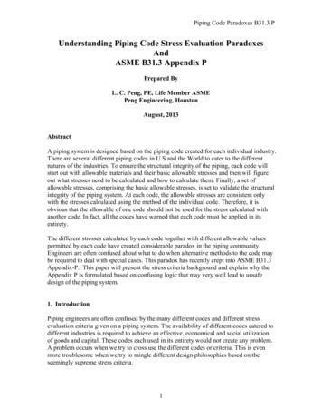
T HE D ESIGN O F P IPE H ANGERS The spans in table are in accordance with MSS StandardPractice SP-69. They do not apply where concentratedweights such as valves or heavy fittings or where changes indirection of the piping system occur between hangers.three fourths the suggested maximum span shown in the tableon the previous page.In considering the vertical section of the pipe on which H-3 andH-4 are shown, it should first be noted that this section of thepipe could be supported by one hanger rather than two asindicated. Two hangers will certainly provide greater stabilitythan will a single hanger. Another deciding factor as to whetherone hanger or a multiple hangers should be used is thestrength of the supporting steel members of the structure. Theuse of two hangers will permit the total riser weight to beproportioned to two elevations of the structure, avoiding theconcentration of all the riser load at one building elevation.For concentrated loads, supports should be placed as closeas possible to the load in order to minimize bending stresses.Where changes in direction of the piping of any critical systemoccur between hangers; it is considered good practice to keepthe total length of pipe between the supports less than 3 4 thefull spans in table below.When practical, a hanger should be located immediatelyadjacent to any change in direction of the piping.The locations for hangers H-5 and H-6 are governed by thesuggested maximum span as well as the position of theconcentrated valve weight. Consequently, H-6 has beenlocated adjacent to the valve, and H-5 at a convenient locationbetween the valve and the 12 inch riser.S AMPLE P ROBLEMIn the sample problem (Figure 1) seven supports are shown onthe 12 inch line, and two on the 6 inch pipe.Note that the hanger H-1 has been placed adjacent to thevalve weight concentration. The proximity of the hanger to thevalve is helpful in keeping the load at terminal connection A toa minimum. Also, the bending stresses induced in the pipe bythe valve weight are kept to a minimum.The location of hanger H-7 will be determined by calculation tosatisfy the condition that no pipe load is to be applied toterminal connection C. It is obvious that by moving the hangeralong the 12 foot section of pipe, the amount of load onconnection C will vary. One support location exists where theentire section will be "balanced", and the load at C equal tozero.The selection of the location for hanger H-2 entails a change indirection of the pipe between two hangers. In order to avoidexcessive overhang of the pipe between hangers H-1 and H-2,the length of pipe between these hangers is made less thanH-2 "5'-0H-1AThe calculations to determine the exact location of H-7 areshown in the section entitled "Hanger Load Calculation".ckCheevlVa"5'-0"4'-0"5'-0"6'-03 '-0"1'-0 2'-0""5 '-011'0""NOTE:ePip12"Allowable load at connection A is 500 lbs.-0"10'3HAllowable load at connection B and C is zero.All bends are 5 diameter bends.All elbows are L.R. Ells.Operating temperature is 1,050 F.All pipe is Sch. 160 A 335 P12.-0"40'H-5"3'-0"8'-0"5'-0"2'-0GaValtvee1 2 '-FIGURE 1 – SAMPLE PROBLEM"5'-0"2'-04 '- 01 2 '-C-0"15'"5'-0H -7H-6H-4"H-8To Su3 '- 6it4 '- 0ip e"H -90"6" P0""5 '- 045 ""7'-0"5'-0"2'-0eGatevlVawww.anvilintl.comBAnvil International, Piping & Pipe Hanger Design and Engineering5
H ANGER L OAD C ALCULATIONS Consider next the 6 inch section of pipe on which H-8 and H-9are shown. One of the requirements for this hanger problem isthat the load at terminal connection B shall be zero. By placingH-9 directly over connection B, we can easily assure that thisload will be zero. Also, this hanger location eliminates anybending stresses in the pipe that would be caused by theweight of the valve and vertical pipe at point B. If H-9 could notbe located at this point due to structural limitations, it would bedesirable to place it as close as possible to the vertical sectionof pipe to keep the cantilever effect to a minimum.Hanger H-8 is located at a convenient distance between H-9and the intersection of the 6 inch and 12 inch pipes. In thisinstance, the location of adequate building structure willdetermine the hanger position.The methods involved in locating hangers for this problem aretypical of those employed by the hanger engineer in the designof pipe supports. Although the individual piping configurationsand structure layout will vary in practically every instance, thegeneral methods outlined above will apply for any criticalpiping system.H ANGER L OAD C ALCULATIONSThe thermal expansion of piping in modern high pressure andtemperature installations makes it necessary for the designerto specify flexible supports, thereby requiring considerablethought to the calculation of hanger loads.Turbine and boiler manufacturers are especially concernedabout the pipe weight on their equipment and often specifythat the loads at pipe connections shall be zero. The hangerdesigner must be certain that the loads on the equipmentconnections of a piping system do not exceed the limitsspecified by the equipment manufacturers.The majority of supports for a high temperature system are ofthe spring type. The designer must work to a high degree ofaccuracy in determining the supporting force required at eachhanger location to assure balanced support, in order to selectthe appropriate size and type of spring support.The first step in the solution of a hanger load problem is toprepare a table of weights. The table for our sample problem(Figure 1) is:TABLE OF WEIGHTS – SAMPLE PROBLEM (FIGURE 1)InsulationWeightWeightTotalUsed InDescriptionWeight(Ca-Si)WeightCalc.12" Sch.160 Pipe 160.3 lb./ft. 20.4 lb./ft. 180.7 lb./ft.375 lb.61.2 lb.436.2 lb.436 lb.12" 1500 lb.Check Valve3370 lb.163.2 lb.3533.2 lb.3533 lb.12" 1500 lb.Gate Valve4650 lb.163.2 lb.4813.2 lb.4813 lb.12" 1500 lb.W.N. Flange843 lb.30.6 lb.873.6 lb.874 lb.12" 5 Dia. Bend1258 lb.160.2 lb.1418.2 lb.1418 lb.45.3 lb./ft. 11.5 lb./ft.56.8 lb./ft.56.8 lb./ft.6" Sch. 160Pipe6" Sch. 16090 L.R. Elbow53 lb.17.2 lb.70.2 lb.70 lb.6" Sch. 16045 Elbow26 lb.6.9 lb.32.9 lb.33 lb.6" 1500 lb.Gate Valve1595 lb.80.5 lb. 1675.5 lb.1676 lb.Draw a free body diagram of the piping between point A andH-2, showing all supporting forces and all valve and pipeweights (Fig. 2). We will consider the loads and supportingforces between A, H-1 and H-2 acting about the axes x-x' andy-y', and apply the three equations:ΣMx-x' 0ΣMy-y' 0ΣV 0.We have prepared a sample problem (Figure 1), in which all ofthe hangers except H-7 have been located. This illustration islimited to as few pipe sections as possible, but incorporatesmost of the problems encountered in hanger load calculations.FIGURE 2 – PLAN VIEWYACheckValve1.5' .5' 1'-0" 1.5'3,533H-15425 ft. RadiusB 3.19'7'-0"4'-0"1.5'The calculation of loads for hangers involves dividing thesystem into convenient sections and isolating each section forstudy. A free body diagram of each section should be drawn tofacilitate the calculations for each hanger load. Most of the freebody diagrams presented here include as large a section ofthe piping system as is practical for a simple arithmeticalsolution to the problem.1,4181.81'The following solution is not intended to illustrate the onlyacceptable solution. Rather, it shows a composite of variousaccepted methods which, for the problem under consideration,produce a well balanced system. Of the approaches that couldbe made to the solution of any problem, there will be onemethod that will produce the best balanced system. Althoughthe individual loads may vary, the total of all hanger loadswould be the same in every case.180.7 lb./ft.12" Sch. 160L.R. Elbow1,084X1.81'H-2'B 3.19'8'-0"X'3'-0"11'-0"Y'6Anvil International, Piping & Pipe Hanger Design and Engineeringwww.anvilintl.com
H ANGER L OAD C ALCULATIONS Note that the value for H-2 on this section of the piping systemrepresents only a part of the total hanger force at H-2. Forclarity, we have labeled this force H-2'. In the calculations forthe next section of pipe beginning at H-2, we will call thehanger force at this point H-2".FIGURE 3 – ELEVATION VIEWH-2'H-3'9'-0"FIGURE 2A– CALCULATING H-2H-2' H-2"2'-0"H-2 5.19'2'-0"7231,4185 ft. Radius(F IG . 2),S TEP II - T AKINGMOMENTS ABOUT AXIS X - X 'H-3" H-4' 11,746 lb.(F IG . 2),ΣMx-x' 0, 1.81(1418) 6.5(542) - 7(H-1) 9.5(3,533) - 11(A) 02,567 3,523 33,564 7(H-1) 11(A)39,564 7(H-1) 11(A)S TEP III - A DDINGFORCESΣV 0,A H-1 H-2' - 3,533 - 542 - 1,418 - 1,084 0A H-1 H-2' 6,577 Ib.Substituting the value H-2', calculated as 1,022 Ib. in Step I,A H-1 1,022 6,577 lb.A 5,555 - H-1S TEP IV – S OLVINGTHE THREE EQUATIONS(1) H-2' 1,022Step I(2) 39,654 7(H-1) 11(A)Step II(3) A 5,555 - (H-1)Step IIISince H-3 H-3' H-3" and H-3' 1293 lb. (see Figure 3),H-3 1,293 lb. 7,228 Ib. 8,521 Ib.Substituting for H-1 in Equation 3,H-4' (10 ft. 15 ft.)(18O.7 Ib./ft.) 4518 Ib.A 5,555 Ib - 5,363 Ib.A 192 lb.; which is below the allowable load at A of 500 Ib.Next, consider the section of pipe between H-2 and H-3 todetermine the weight distribution, between these two points, ofthe 4ft. section of pipe and the five diameter bend.ΣMH-3' 0,1.81(1,418) 7(723)-9(H-2") 0H-2" 848 Ib.H-2 H-2' H-2" 1,022 lb. 848 lb. 1,870 Ib.www.anvilintl.comH-4'H-3" (10 ft. 30 ft.)(180.7 Ib./ft.) 7,228 Ib.39,654 7(H-1) 11(5,555 - H-1)H-1 5,363 Ib.2(723) 7.19(1418)-9(H-3') 0H-3' 1,293 Ib.is maintained. It is not recommended,however, to select arbitrary values forthese two forces; instead, the load foreach hanger should be such that theelevation of the pipe attachment isabove the midpoint of the length of pipesupported by the hanger. Thus, thesupport will be located above the pointwhere one could consider the weight ofthe pipe column acting, therebyavoiding a condition where the locationof the support lends itself to the"tipping" tendency of the pipe when thesupport is located below this point.Since there is 10 ft. of vertical pipeabove H-3" and 40 ft. of pipe between H-3" and H-4', let H-3"support 10 ft. plus 30 ft. of pipe load:Solving Equation (2) by subsitituting for A 5555 - H-1,ΣMH-2" 0,10'-0"MOMENTS ABOUT AXIS Y - Y 'ΣMy-y' 0, 1.81(1418) 8(1 084) - 11(H-2') 02,567 8,672 11(H-2')H-2' 1,022 Ib.65'-0"S TEP 1 - T AKING40'-0"B Radius x .637, or 5 ft. x .637 3.185 ft.In the next free body diagram (Figure 4) consider the 65 ft.vertical section of the piping system to determine thesupporting forces for H-3" and H-4'.FIGURE 4 – ELEVATION VIEWIt is apparent that the combined forcesH-3" and H-4' equals 65 ft. x 180.7 Ib./ft.Further, both H-3" and H-4' could beH-3"any value, provided the relationship15'-0"Also, note that we have considered the weight of the 90 bendacting at the center of gravity of the bend. The distance B isdetermined from the Chart on page 10 which has been drawnfor convenience:Consider the piping between H-4' and H-5 to determine theweight distribution of the 5 diameter bend and the 5 ft. ofhorizontal pipe:ΣMH-4" 01.81(1,418) 7.5(904)-10(H-5') 0H-5' 935 Ib.ΣMH-5' O2 .5(904) 8.1 9(148)-10(H-4") 0H-4" 1,387 Ib.H-4 H-4' H-4" 4518 lb. 1,387 lb. 5,905 Ib.Anvil International, Piping & Pipe Hanger Design and Engineering7
H ANGER L OAD C ALCULATIONS FIGURE 5FIGURE 6 – ELEVATION VIEWFIGURE 7 – PLAN VIEWH-4"H-5'10'-0"H-3"10'-0"YR17.5'.27'2.5'70 (Elbow)1.81'12'-0"30'-0"5 ft. Radius16'-0"15'-0" 10'-0"H-4'3.78'1,41814.94' x 56.8 lbs/ft 849 lbs904H-8 Mx-x'' 019(70) 2.66(341) 5.03(33) - 9(H-8) 12.78(849) 20.73(70) - 21R1 013,387 9(H-8)21 (R1) V 0,.07'6.01' x 56.8 lbs/ft 341 lbs2.34'70.19'XH-94.81'R1 H-8 H-9 - 2,031- 70 - 341 - 33 - 849 - 70 0R1 H-8 H-9 3,394 Ib.Since H-9 has been calculated as 2,258 Ib.2.66'.07(33) 2.34(341) 4.81(70) 5(2,031) - 5(H-9) 0H-9 2,258 Ib.33(Elbow).03'5'-0" My-y' 04'-0"It is obvious that some portion of the weight of the 6 in. pipebetween the 12 in. line and H-8 must be supported by H-5 andH-6. Therefore, before proceeding through H-5 and H-6,calculate this pipe weight load R1, and introduce it into the freebody diagram for H-5 and H-6.5'-0"Y'X'1,676 (Valve)355 (Pipe)2,031 TotalR1 H-8 3,394 lb. - 2,258 lb. 1,136 Ib.H-8 1,136 lb. - R1Substituting this value for H-8 in the Equation13,387 9(H-8) 21R113,387 9(1,136 lb. - R1) 21(R1)R1 264 Ib.H-8 1,136 - R1 1136 lb. - 264 Ib 872 Ib.8Anvil International, Piping & Pipe Hanger Design and Engineeringwww.anvilintl.com
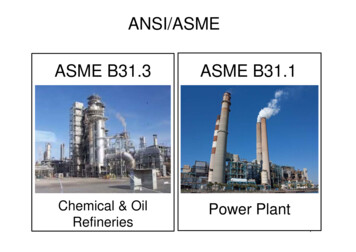
H ANGER L OAD C ALCULATIONS FIGURE 8 – ELEVATION VIEWFIGURE 9H-5"EH-615'-0"5'-0".75'E2181.5'2'-0"'1.5'218E 1.09'.75'3'-0"3.25 Ft. x 56.8 185R1 2643.5'2'-0"'3.25'1.5'1.5' Radius5'-0"1,8074,813994Dimension E is determinedfrom the Chart on page 10.1 2 Weight12" ELL 218For the sample problem,E .726 x 1.5 ft. 1.09 ft.TOTAL 449The free body diagram shown in Figure 8 extends from H-5through the 12 in. 90 elbow. This is intended to illustrate thatthe weight of the 90 elbow may be considered as supportedon a beam which passes through the center of gravity of theelbow and rests on the extensions of the tangents as shown inFigure 9.Solving for distance X,In Figure 8,As a final step, check to ensure that the weight of the entirepiping system is equal to the total supporting forces of thehangers plus the pipe weight load to be supported by theequipment connections:ΣMH-5" 0, 2(449) 5(1,807) 11.5(4,813) - 15(H-6) 15.75(994) 18.91(218) 0H-6 5,671 Ib.ΣMH-6 0,ΣMC 0,.54(436) - X(H-7) 6(1,626) 10.91(218) 0X(H-7) 12,369X(3515) 12,369X 3.52 ft.3.5(4,813) 10(1,807) 13(449) - .75(994)- 3.91(218) - 15(H-5") 0SUMMARY –– SUPPORT FORCESH-5" 2,610 Ib.H-5 H-5' H-5" 935 lb. 2,610 Ib. 3,545 Ib.Piping SystemSupport ForcesPlus TerminalWeight (Lbs) Point Loads, Ib109.5 ft. of 12" Pipe @ 180.7 Ib./ft.FIGURE 10 – ELEVATION VIEW19,787A 1924,254H-1 5,363872H-2 1,8701,730H-3 8,521140H-4 5,90533H-5 3545(1) 12" 1,500 lb. Check Valve @ 3,533 Ib.3,533H-6 5,671(1) 12" 1,500 lb. Gate Valve @ 4,813 lb.4,813H-7 3,515(3) 12" 5 Dia. Bends @ 1418 lb.H-71.5'(2) 12" 90 L.R. Ells @ 436 lb.CX4.5'30.45 ft. of 6" Pipe @ 56.8 Ib./ft.(2) 6" 90 L.R. Ells @ 70 lb.1.5'Radius(1) 6" 45 Ell @33 lb.C .96'1.09'1 2Weight of Ell 218 lbs4.91'.54'5.46'1,6264362' x 180.7 lbs./Ft. 361 lbs.12" Flange 874 lbs.Total 1235 lbs.(1) 12" 1,500 Ib. WN Flange @ 874 lb.874(1) 6" 1,500 lb. Gate Valve @ 1,676 lb.1,676Total Weight of Piping System.H-8 872H-9 2,25837,712 Total 37,712The Figure 10 diagram shows a method for arriving at thelocation of H-7 which will allow zero load on connection C.The value of H-7 is equal to the weight of the piping section:H-7 218 lb. 1,626 lb. 436 lb. 1,235 Ib. 3,515 Ib.www.anvilintl.comAnvil International, Piping & Pipe Hanger Design and Engineering9
H ANGER L OAD C ALCULATIONS CALCULATED ARC DISTANCES FOR BENDS AND WELDING ELBOWS1.2DT1.1"E" CurveE1.0cgθ0.9ED & E in Inches for 1" Radius0.8RT0.7θ/20.6DA0.5"D" Curve0.40.30.2D R x [TAN(θ/2) 2/θ - 2 x CSC(θ)]E 2 x R x [CSC(θ) 1/θ]T R x 50160170180160170180ø in DegreesCENTER OF GRAVITY OF AN ARC1.0"A" Curve0.9A [2 x R x SIN(θ/2)]θB R x [1 - COS(θ)θC R x SIN(θ)θ0.8A, B &C in Inches for 1" Radius0.70.60.50.4Rcg0.3θθ/20.2B"C" CurveC"B" � in Degrees10Anvil International, Piping & Pipe Hanger Design and Engineeringwww.anvilintl.com
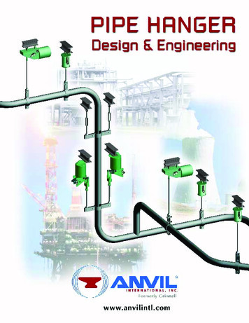
T HERMAL M OVEMENT C ALCULATIONS T HERMAL M OVEMENTSS TEP 1 – C HART V ERTICAL M OVEMENTSThe next step in the design of pipe hangers involves thecalculation of the thermal movements of the pipe at eachhanger location. Based on the amount of vertical movementand the supporting force required, the engineer can mosteconomically select the proper type hanger (i.e. ConstantSupport, Variable Spring, or Rigid Assembly).Draw the piping system of Figure 1 and show all knownvertical movements of the piping from its cold to hot, oroperating, position (see Figure 11). These movements willinclude those supplied by the equipment manufacturers forthe terminal point connections. For the illustrated problem,the following vertical movements are known:The determination of piping movements to a high degree ofaccuracy necessitates a highly complicated study of the pipingsystem. The simplified method shown here is one which givessatisfactory approximations of the piping movements.Point A -- 2 in. up, cold to hotWhenever differences occur between the approximations andactual movements, the approximation of the movement willalways be the greater amount.H-4 - 0 in., cold to hotPoint B -- 1 16 in. up, cold to hotPoint C -- 1 8 in. down, cold to hotThe operating temperature of the system is given as 1,050 F.FIGURE 11 – VERTICAL MOVEMENTSH -2H -12" UPA4 '-0ckCheevlaV11'-0 "12""1 1 '-D"9 '- 0P ip15'-0 "40'-0 "eH -30"5 '- 0H -52H -7H -6H -4"1 2 'C13'- 0 "GateValve3'-611 2 '-F2 '- 0"4 '-0"ip e"H -90"6" P3 '-6JH -8G"0 '- 0 8 "0"4 '-05 '-0"1 8"Down"45 H10'- 0 "-0 "9'E1 16" UPBwww.anvilintl.comeG atevlaVAnvil International, Piping & Pipe Hanger Design and Engineering11
T HERMAL M OVEMENT C ALCULATIONS Referring to the thermal expansion table (page 63), thecoefficient of expansion for low-chrome steel at 1,050 F is.0946 in.FIGURE 13C – SECTION E-J42'-0"32'-0"30'-0"Calculate the movements at points D and E by multiplying thecoefficient of the expansion by the vertical distance of eachpoint from the position of zero movement on the riser D E:55 ft. x .0946 in./ft. 5.2 in. up at D17'-0"3.5'H-5EH-6H-7J.46"1.89"20 ft. x .0946 in./ft. 1.89i n. down at E1.43"56f7S TEP 2 – S ECTION A-DMake a simple drawing of the piping between two adjacentpoints of known movement, extending the piping into a singleplane as shown for the portion between A and D.FIGURE 12 – SECTION A - D3.20"5.20"122"AH-14'-0"DH-2 7 3.5/42 x 1.43 0.12in. f 30/42 x 1.43 1.02in. H-7 0.12in. 0.46in. 0.58in.down F 1.02in. 0.46in. 1.48in. down 6 17/42 x 1.43 0.58in. H-6 0.58in. 0.46in. 1.04in. down 5 32/42 x 1.43 1.09in. H-5 1.09in. 0.46in. 1.55in. downS TEP 5FIGURE 14 – SECTION G-HDraw the section G-H. The movementat G is equal to the movement at Fminus the expansion of the leg G-F:22'-0"31'-0" G 1.48in. down - (4ft. x .0946in./ft) G 1.10in. downThe vertical movement at any hanger location will beproportional to its distance from the end points:G1.10" 1 4 31 x 3.20 .41in.FThe vertical movement at H-1 .41 in. 2 in. H-1 2.41 in. upFIGURE 15A – SECTION B-H.91"H-9The vertical movement at H-2 2.27 in. 2 in. H-2 4.27 in. upThe movement at H is equal to themovement of the terminal point B(1 16 in. up) plus the expansion of theleg B-H: H .0625in. up (9ft. x .0946in./ft) H 0.91in.upHATH-3FIG. 13A – MOVEMENT AT H-3To calculate the vertical movement atH-3, multiply its distance from H-4 bythe coefficient of expansion.Elevation9'-0" Since H-9 is located at point H,.0625"H-3 H-9 H 0.91in.up3.78" H-3 40 ft. x .0946 in./ft. 3.78 in.up Y 12/23.1 x 2.01in. 1.04in. H-8 1.10in. - 1.04in. .06in. downB40'-0" H-3 3.78 in. upElevation1.48" 2 22 31 x 3.20 2.27in.S TEP 3 – M OVEMENT4'-0"FIGURE 15B – SECTION G-H23.1'H-9H-4 0".91"2.01"0"S TEP 4 – S ECTION E-JThe next section with two points ofknown movement is the length E-J.Movement at E was calculated as1.89 in. down. Movement at J is equal tothe movement at the terminal pointC (1/8 in. down) plus the amount ofexpansion of the leg C-J: J .125in. (3.5ft. x 0946in./ft) .46in. down12H12'-0"H-8{G1.10"yFIG. 13B – SECTION E-JC1.25"3.5'After calculating the movement ateach hanger location it is oftenhelpful, for easy reference whenselecting the appropriate typehanger, to make a simple table ofhanger movements like the oneshown at the right.J.46"Anvil International, Piping & Pipe Hanger Design and EngineeringHanger No. . MovementH-1 . 2.41" upH-2 . 4.27" upH-3 . 3.78" upH-4 . 0"H-5 . 1.55" downH-6 . 1.04" downH-7 . 0.58" downH-8 . 0.06" downH-9 . 0.91" upwww.anvilintl.com
S ELECTIONOF THEP ROPER H ANGER S ELECTION O F T HE P ROPER H ANGERSelection of the appropriate type hanger for any givenapplication is governed by the individual piping configurationand job requirements. Job specifications covering hangertypes, however, are of necessity written in broad terms, andsome emphasis is placed on the good judgement of thehanger engineer to ensure a satisfactory, yet economical,system.The type of hanger assemblies are generally classified asfollows:(1) Flexible hangers, which include hangers of the constantsupport and variable spring types.(2) Rigid hangers, such as rod hangers and stanchions.(3) RollersThe location of anchors and restraints is not usually considered a responsibility of the hanger designer. Since it isnecessary to determine the location of anchors and restraintsbefore accurate and final stress analysis is possible, they areconsidered a part of piping design.F LEXIBLE H ANGERSWhen a pipe line expands vertically as a result of thermalexpansion it is necessary to provide flexible pipe supportswhich apply supporting force throughout the expansion andcontraction cycle of the system.There are two types of Flexible hangers: Variable Spring Constant Support.Constant Support hangers provide constant supporting forcefor piping throughout its full range of vertical expansion andcontraction. This is accomplished through the use of a helicalcoil spring working in conjunction wit
design of pipe hangers often must gather a considerable amount of reference data peculiar only to the hanger calculations for his current project. It is the purpose of this article to present a compilation of all information necessary for the design of hangers, including a technical section de