Transcription
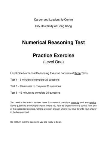
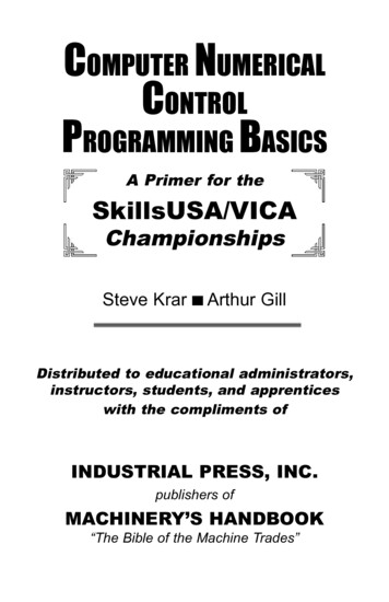
COMPUTER NUMERICALCONTROLPROGRAMMING BASICSA Primer for theSkillsUSA/VICAChampionshipsSteve KrarArthur GillDistributed to educational administrators,instructors, students, and apprenticeswith the compliments ofINDUSTRIAL PRESS, INC.publishers ofMACHINERY’S HANDBOOK“The Bible of the Machine Trades”
ComputerNumericalControlProgrammingBasicsSteve Krar Arthur GillThis book is not intended for sale under any circumstances.INDUSTRIAL PRESS INC.200 Madison Avenue, New York, NY 10016
CONTENTSSECTIONPAGEForeword1Preface7Cartesian Coordinate System7Machines Using CNC9Programming Systems11Point-to-Point or Continuous Path13Point-to-Point Positioning14Continuous Path (Contouring)15Interpolation15Programming Format17Programming for Positioning23Work Settings and Offsets26CNC Bench-Top Milling and Turning Centers30CNC Programming Hints — Milling32Milling and Drilling Programming34CNC Programming Hints – Turning38Fanuc Compatible Programming39Turning Programming40
PrefaceThe term numerical control is a widely accepted and commonlyused term in the machine tool industry. Numerical control (NC)enables an operator to communicate with machine tools through aseries of numbers and symbols.NC which quickly became Computer Numerical Control (CNC) hasbrought tremendous changes to the metalworking industry. Newmachine tools in CNC have enabled industry to consistentlyproduce parts to accuracies undreamed of only a few years ago.The same part can be reproduced to the same degree of accuracyany number of times if the CNC program has been properly prepared and the computer properly programmed. The operatingcommands which control the machine tool are executed automatically with amazing speed, accuracy, efficiency, and repeatability.The ever-increasing use of CNC in industry has created a need forpersonnel who are knowledgeable about and capable of preparingthe programs which guide the machine tools to produce parts tothe required shape and accuracy. With this in mind, the authorshave prepared this textbook to take the mystery out of CNC - toput it into a logical sequence and express it in simple languagethat everyone can understand. The preparation of a program isexplained in a logical step-by-step procedure, with practical examples to guide the student.Cartesian Coordinate SystemAlmost everything that can be produced on a conventional machine tool can be produced on a computer numerical controlmachine tool, with its many advantages. The machine tool movements used in producing a product are of two basic types: pointto-point (straight-line movements) and continuous path (contouringmovements).The Cartesian, or rectangular, coordinate system was devised bythe French mathematician and philosopher Rene’ Descartes. Withthis system, any specific point can be described in mathematical7
terms from any other point along three perpendicular axes. Thisconcept fits machine tools perfectly since their construction isgenerally based on three axes of motion (X, Y, Z) plus an axis ofrotation. On a plain vertical milling machine, the X axis is thehorizontal movement (right or left) of the table, the Y axis is thetable cross movement (toward or away from the column), and theZ axis is the vertical movement of the knee or the spindle. CNCsystems rely heavily on the use of rectangular coordinates because the programmer can locate every point on a job precisely.When points are located on a workpiece, two straight intersectinglines, one vertical and one horizontal, are used. These lines mustbe at right angles to each other, and the point where they cross iscalled the origin, or zero point (Fig. 1)Fig. 2 The three-dimensionalcoordinate planes (axes) used inCNC. (The Superior ElectricCompany)Fig. 1 Intersecting lines form right angles andestablish the zero point (Allen-Bradley)The three-dimensional coordinate planes are shown in Fig. 2. TheX and Y planes (axes) are horizontal and represent horizontalmachine table motions. The Z plane or axis represents the verticaltool motion. The plus ( ) and minus (-) signs indicate the directionfrom the zero point (origin) along the axis of movement. The fourquadrants formed when the XY axes cross are numbered in acounterclockwise direction (Fig. 3). All positions located in quadrant 1 would be positive (X ) and positive (Y ). In the secondquadrant, all positions would be negative X (X-) and positive (Y ).In the third quadrant, all locations would be negative X (X-) andnegative (Y-). In the fourth quadrant, all locations would be positive X (X ) and negative Y (Y-).8
Fig. 3 The quadrants formed when the X and Y axes cross are used to accurately locatepoints from the XY zero, or origin, point. (Allen-Bradley)In Fig. 3 , point A would be 2 units to the right of the Y axis and 2units above the X axis. Assume that each unit equals 1.000. Thelocation of point A would be X 2.000 and Y 2.000. For point B,the location would be X 1.000 and Y - 2.000. In CNC programming it is not necessary to indicate plus ( ) values since these areassumed. However, the minus (-) values must be indicated. Forexample, the locations of both A and B would be indicated asfollows:ABX2.000X1.000Y2.000Y-2.000Machines Using CNCEarly machine tools were designed so that the operator wasstanding in front of the machine while operating the controls. Thisdesign is no longer necessary, since in CNC the operator nolonger controls the machine tool movements. On conventionalmachine tools, only about 20 percent of the time was spent removing material. With the addition of electronic controls, actual timespent removing metal has increased to 80 percent and evenhigher. It has also reduced the amount of time required to bringthe cutting tool into each machining position.9
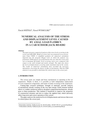
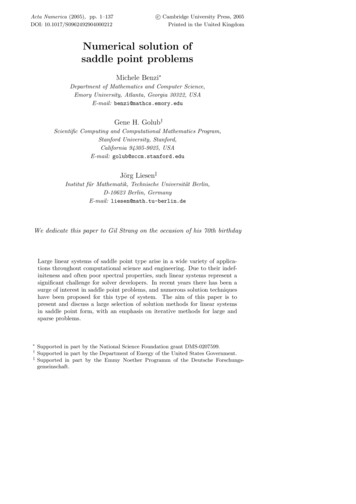
Machine TypesLatheThe engine lathe, one of the most productive machine tools, hasalways been an efficient means of producing round parts (Fig.4). Most lathes are programmed on two axes. The X axis controls the cross motion of the cutting tool.Negative X (X-) moves the tool towards the spindlecenterline; positive X moves the tool away from the spindlecenterline. The Z axis controls the carriage travel toward or away fromthe headstock.Fig. 4 The main axes of a lathe or turning center. (Emco Maier Corp)Milling MachineThe milling machine has always been one of the most versatilemachine tools used in industry (Fig. 5). Operations such asmilling, contouring, gear cutting, drilling, boring, and reaming areonly a few of the many operations which can be performed on amilling machine. The milling machine can be programmed onthree axes: The X axis controls the table movement left or right. The Y axis controls the table movement toward or away fromthe column. The Z axis controls the vertical (up or down) movement ofthe knee or spindle.10
Z axisX axisY axisFig. 5 The main axes of a vertical machining center. (Denford Inc.)Programming SystemsTwo types of programming modes, the incremental system andthe absolute system, are used for CNC. Both systems haveapplications in CNC programming, and no system is either right orwrong all the time. Most controls on machine tools today arecapable of handling either incremental or absolute programming.PositioningReference Point SystemsIncrementalAbsoluteIncremental program locations are always given as the distanceand direction from the immediately preceding point (Fig. 6). Command codes which tell the machine to move the table, spindle,and knee are explained here using a vertical milling machine asan example:11
Fig. 6 A workpiece dimensioned in the incremental system mode. (Icon Corporation) A “X plus” (X ) command will cause the cutting tool to belocated to the right of the last point.A “X minus” (X-) command will cause the cutting tool to be located to the left of the last point.A “Y plus” (Y ) command will cause the cutting tool to belocated toward the column.A “Y minus” (Y-) will cause the cutting tool to be located awayfrom the column.A “Z plus” (Z ) command will cause the cutting tool or spindleto move up or away from the workpiece.A “Z minus” (Z-) moves the cutting tool down or into the workpiece.In incremental programming, the G91 command indicates to thecomputer and MCU (Machine Control Unit) that programming is inthe incremental mode.Absolute program locations are always given from a single fixedzero or origin point (Fig. 7). The zero or origin point may be aposition on the machine table, such as the corner of the worktableor at any specific point on the workpiece. In absolute dimensioningand programming, each point or location on the workpiece is givenas a certain distance from the zero or reference point.12
Fig. 7 A workpiece dimensioned in the absolute system mode. Note: All dimensions are givenfrom a known point of reference. (Icon Corporation) A “X plus” (X ) command will cause the cutting tool to belocated to the right of the zero or origin point.A “X minus” (X-) command will cause the cutting tool to be located to the left of the zero or origin point.A “Y plus” (Y ) command will cause the cutting tool to belocated toward the column.A “Y minus” (Y-) command will cause the cutting tool to be located away from the column.In absolute programming, the G90 command indicates to thecomputer and MCU that the programming is in the absolute mode.Point-to-Point or Continuous PathCNC programming falls into two distinct categories (Fig. 8). Thedifference between the two categories was once very distinct.Now, however, most control units are able to handle both point-topoint and continuous path machining. A knowledge of both programming methods is necessary to understand what applicationseach has in CNC.13
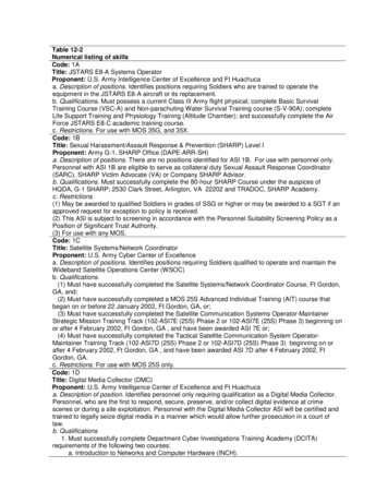
CNC PositioningSystemsContinuous PathorContouringPoint-to-PointorPositioningFig. 8 Types of CNC positioning systems (Kelmar Associates)Point-to-Point PositioningPoint-to-point positioning is used when it is necessary to accurately locate the spindle, or the workpiece mounted on the machine table, at one or more specific Iocations to perform suchoperations as drilling, reaming, boring, tapping, and punching (Fig.9). Point-to-point positioning is the process of positioning from onecoordinate (XY) position or location to another, performing themachining operation, and continuing this pattern until all theoperations have been completed at all programmed locations.Fig. 9 The path followed by point-to-point positioning to reach various programmed points(machining locations) on the XY axis. (Kelmar Associates)In Fig. 9 point 1 to point 2 is a straight line, and the machinemoves only along the X axis; but points 2 and 3 require thatmotion along both the X and Y axes takes place. As the distancein the X direction is greater than in the Y direction, Y will reach its14
position first, leaving X to travel in a straight line for the remainingdistance. A similar motion takes place between points 3 and 4.Continuous Path (Contouring)Contouring, or continuous path machining, involves work such asthat produced on a lathe or milling machine, where the cutting toolis in contact with the workpiece as it travels from one programmedpoint to the next. Continuous path positioning is the ability tocontrol motions on two or more machine axes simultaneously tokeep a constant cutter-workpiece relationship. The programmedinformation in the CNC program must accurately position thecutting tool from one point to the next and follow a predefinedaccurate path at a programmed feed rate in order to produce theform or contour required (Fig. 10)Fig. 10 Types of contourmachining (A) Simplecontour; (B) complexcontour (Allen Bradley)InterpolationThe method by which contouring machine tools move from oneprogrammed point to the next is called interpolation. This ability to15
merge individual axis points into a predefined tool path is built intomost of today’s MCUs. There are five methods of interpolation:linear, circular, helical, parabolic, and cubic. All contouring controlsprovide linear interpolation, and most controls are capable of bothlinear and circular interpolation. Helical, parabolic, and cubicinterpolation are used by industries that manufacture parts whichhave complex shapes, such as aerospace parts and dies for carbodies.Linear InterpolationLinear Interpolation consists of any programmed points linkedtogether by straight lines, whether the points are close together orfar apart (Fig. 11). Curves can be produced with linear interpolation by breaking them into short, straight-line segments. Thismethod has limitations, because a very large number of pointswould have to be programmed to describe the curve in order toproduce a contour shape.A contour programmed in linear interpolation requires the coordinate positions (XY positions in two-axis work) for the start andfinish of each line segment. Therefore, the end point of one line orsegment becomes the start point for the next segment, and so on,throughout the entire program.Fig. 11 An example of two-axis linear interpolation. (Kelmar Associates)16
Circular InterpolationThe development of MCUs capable of circular interpolation hasgreatly simplified the process of programming arcs and circles. Toprogram an arc (Fig. 12), the MCU requires only the coordinatepositions (the XY axes) of the circle center, the radius of the circle,the start point and end point of the arc being cut, and the directionin which the arc is to be cut (clockwise or counterclockwise) SeeFig. 12. The information required may vary with different MCUs.Fig. 12 For two-dimensional circular interpolation the MCU must be supplied with the XY axis,radius, start point, end point, and direction of cut. (Kelmar Associates)Programming FormatWord address is the most common programming format used forCNC programming systems. This format contains a large numberof different codes (preparatory and miscellaneous) that transfersprogram information from the part print to machine servos, relays,micro-switches, etc., to manufacture a part. These codes, whic
CNC Programming Hints – Turning 38 Fanuc Compatible Programming 39 Turning Programming 40. 7 The term numerical control is a widely accepted and commonly used term in the machine tool industry. Numerical control (NC) enables an operator to communicate with machine tools through a series of numbers and symbols. NC which quickly became Computer Numerical Control (CNC) has brought