Transcription
Haas Factory OutletA Division of Productivity IncHFOMN/Haas CNC SeriesMill Operator Training ManualNG2 Next Generation Control &VPS (Visual Programming System)REV 12/27/18
This Manual is the Property of Productivity IncThe document may not be reproduced without the express written permission ofProductivity Inc, nor may it be sold.The content must not be altered, nor may the Productivity Inc name be removedfrom the materials.This material is to be used as a guide to operation of the machine tool. TheOperator is responsible for following Safety Procedures as outlined by theirinstructor or manufacturer’s specifications.NOTE: Downloading and/or other use of this manual does not certify completionof the Training course. This manual is for reference only.To obtain permission, please contact trainingmn@productivity.com.
For more information onAdditional Training Opportunities or our Classroom SchedulesContact the Productivity Inc or MMT Applications DepartmentMinneapolis: 763.476.8600Cedar Rapids: 319.734.3403Omaha: 402.330.2323MMT Denver: 800-947-8665MMT Salt Lake City: 801.886.2221Visit us on the Web: www.productivity.com or www.mmtproductivity.comFor Minnesota Classes, Click on the Training Registration Button trainingmn@productivity.comProductivity Inc – Haas CNC Mill Operator Manual – NG2 – 12/27/18Page 3
Productivity Inc – Haas CNC Mill Operator Manual – NG2 – 12/27/18Page 4
Haas CNC Mill Operator ManualTable of ContentsINTRODUCTION TO BASIC VERTICAL MILL OPERATION . 7THE CARTESIAN COORDINATE SYSTEM . 9ABSOLUTE AND INCREMENTAL POSITIONING .10ABSOLUTE AND INCREMENTAL EXERCISE .11VERTICAL MACHINING CENTER TRAVELS. 14THE MACHINE COORDINATE SYSTEM - MACHINE HOME POSITION . 16WORK COORDINATE SYSTEM .17TOOL LENGTH OFFSET . 19THE HAAS NEXT GENERATION CONTROL . 2016 SOFTWARE CONTROL DISPLAY .21NGA CONTROL DISPLAY.22KEYBOARD INTRODUCTION .23NEXT GENERATION KEYBOARD CHANGES.24DISPLAY KEYS.25SETTINGS LIST .351 – FUNCTION KEYS .402 – JOG KEYS .403 – OVERRIDE KEYS .415 – CURSOR KEYS .426 AND 7 – ALPHA KEYS AND NUMERIC KEYS .428 – MODE KEYS .43ATC (AUTOMATIC TOOL CHANGE). 51SETTING TOOL LENGTH & WORK ZERO OFFSETS . 52SET UP PROCEDURE . 53WORK OFFSETS (X AND Y PART ZEROS) .53TOOL LENGTH OFFSETS .53PROGRAM PROOFING AND RUNNING IN MEMORY.53HAAS MILL CONTROL TIPS .54GENERAL TIPS .54CONTROL TIPS.54Productivity Inc – Haas CNC Mill Operator Manual – NG2 – 12/27/18Page 5
POSIT (POSITION) .55PROGRAMMING .56TOOLROOM MILL ORIENTATION AND WALK AROUND: . 59POWER-UP PROCEDURE .601.A.III – MACHINE RESTART / ZERO RETURN PROCEDURE .60TOOLROOM MILL SAFETY .61MAINTENANCE OF THE TM SERIES MILL .61VIRTUAL PROGRAMMING SYSTEM . 65FACE MILLING .67SQUARE CONTOURING .70CIRCULAR POCKET MILLING: .73SQUARE POCKET MILLING: .75DRILL ROUTINES: .77ENGRAVING: .81FINAL PROGRAM CREATED USING VPS.82THREAD MILLING: .86THREAD MILLING PROGRAM .89Productivity Inc – Haas CNC Mill Operator Manual – NG2 – 12/27/18Page 6
Introduction to Basic Vertical Mill OperationWelcome to Productivity, Inc., your local Haas Factory Outlet (H.F.O.) for the Haas Mill Operator Class.This class is intended to give a basic understanding of the set-up and operation of a Haas MachiningCenter.After 1945 design of wings for the US Air Force were becoming extremely complex and hard tomanufacture using conventional machine tools. MIT developed a machine that was able to control acutting tool path with a series of straight lines defined by axial coordinates at prescribed feed rates.The first NC machine tool was introduced to the defense and aerospace industry by MIT in 1952. Thecontour of a constantly changing curvature could be described by a series of short lines determined by aseries of coordinate in three axes.The first machine tools were run with instructions or programs punched out on paper tape. The files ofthe early machine tools were often in the format which later became called G-code. The reason for thename being that many of the lines of text began the letter G.In an NC machine, the tool is controlled by a code system that enables it to be operated with minimalsupervision and with a great deal of repeatability. "CNC" (Computerized Numerical Control) is the sametype of operating system, with the exception that a computer monitors the machine tool.The same principles used in operating a manual machine are used in programming a NC or CNCMachine. The main difference is that instead of cranking handles to position a slide to a certain point,the dimension is stored in the memory of the machine control once. The control will then move themachine to these positions each time the program is run.The operation of the VF-Series Vertical Machining Center requires that a part program be designed,written, and entered into the memory of the control. There are several options for getting theseprograms to the control. RS-232 (serial port with a computer), 3.5” Floppy Disk, Ethernet / Networking/and USB are all viable ways to transmit and receive programs.In order to operate and program a CNC controlled machine, a basic understanding of machiningpractices and a working knowledge of math are necessary. It is also important to become familiar withthe control console and the placement of the keys, switches, displays, etc., that are pertinent to theoperation of the machine.This manual can be used as both an operator's manual and as a programmer's manual. It is intended togive a basic understanding of CNC programming and its applications. It is not intended as an in-depthstudy of all ranges of machine use, but as an overview of common and potential situations facing CNCprogrammers. Much more training and information is necessary before attempting to program on themachine.The programming section of this manual is meant as a supplementary teaching aid to users of the HAASVertical Machining Center. The information in this section may apply in whole or in part to the operationof other CNC machines. Its use is intended only as an aid in the operation of the HAAS VerticalMachining Center.Updated CK 12/27/18Productivity Inc – Haas CNC Mill Operator Manual – NG2 – 12/27/18Page 7
NotesProductivity Inc – Haas CNC Mill Operator Manual – NG2 – 12/27/18Page 8
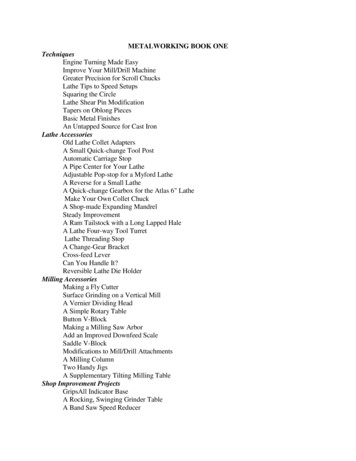
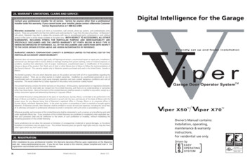
The Cartesian Coordinate SystemThe first diagram we are concerned with is called a NUMBER LINE. This number line has a zero referencepoint location that is called an ABSOLUTE ZERO and may be placed at any point along the number line.“X” axisThe number line also has numbered increments on either side of absolute zero.Moving away from zero to the right are positive increments. Moving away from zero to the left arenegative increments. The “ ”, or positive increments, are understood, therefore no sign is needed. Weuse positive and negative signs along with increment value's to indicate its relationship to zero on theline.Our concern is the distance and the direction from zero and is labeled as “Absolute Programming”Remember that zero may be placed at any point along the line, and that once placed, one side of zerohas negative increments and the other side has positive increments.Vertical Number Line known as the “Y” axisProductivity Inc – Haas CNC Mill Operator Manual – NG2 – 12/27/18Page 9
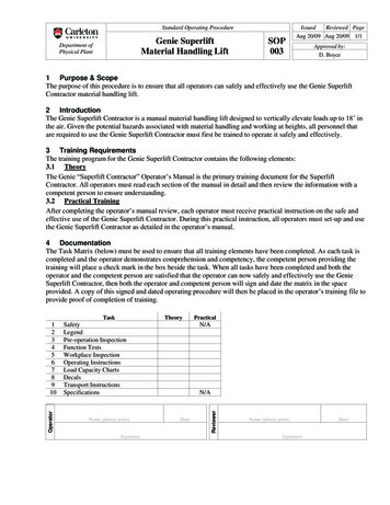
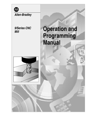
Absolute and Incremental PositioningThere are two different systems used in positioning our machine. Both will “steer” the machine where weneed it to go, both will net the same results. The reason we use one more than the other, is flexibility.Below we will talk about both, and they are the first two “G-Codes”Absolute Positioning:With absolute positioning, we tell the machine where to move referenced to a common point, called X0Y0 and Z0. Every time we need to move to a certain position, the ending point of that move is in directrelationship to this “common point”G90 Absolute PositioningProgram to move the machine to these4 hole locations when using G90 (Abs.)X 1.0000 Y 1.0000X 9.0000 Y 1.0000X 9.0000 Y 9.0000X 1.0000 Y 9.0000Incremental Positioning:With incremental positioning, we are telling the machine where to go in relationship to where it currentlyis at. Basically like a set of directions given from where the machine stopped last.G91 Incremental PositioningProgram to move the machine to the same4 hole locations using G91 (Incr.)X 1.0000 Y 1.0000X 8.0000Y 8.0000X -8.0000When do we decide which to use?We switch between the two when it is more convenient. One example is look at the above 2 prints.Sometimes the print doesn’t call out the hole-locations, but will give the distance between the holes.Productivity Inc – Haas CNC Mill Operator Manual – NG2 – 12/27/18Page 10
Absolute and Incremental ExerciseG91 INCREMENTALG90 ABSOLUTEP1X0Y tivity Inc – Haas CNC Mill Operator Manual – NG2 – 12/27/18X0Y -2.5Page 11
This diagram shows a front view of the grid as it would appear on the mill. This view shows the X and Yaxes as the operator faces the mill. Note that at the intersection of the two lines, a common zero pointis established.Fig. 1-4: Operator’s working grid.Whenever we set a zero somewhere on the X axis and somewhere on the Y axis, we have automaticallycaused an intersection of the two lines. This is known as “zero”, where our X and Y lines would both beat a value of 0. We will move this point to a “Zero” position on our part so that we can steer the machineto locations that relate to our print. Another term for this “Zero” position is the origin of the part.Productivity Inc – Haas CNC Mill Operator Manual – NG2 – 12/27/18Page 12
The following illustration shows the X & Y directions of travel on a vertical machining center with respectto a part print. It shows the positive and negative positions that our spindle would have to move withrespect to the x and y axis. Also note where these two axis meet, they create a common point of “zero”where they both are at the value of “0” at the same point.Vertical machining centers have 3 axis of travel. We have talked about two of them, the X (left to rightmovement), the Y (moving the part towards and away from the operator), but the last to discuss is theZ. The Z axis moves the milling spindle up or away from the part in the positive direction, and towards orinto the part in the negative direction. Now that we have discussed all 3 of the axis, we can take a lookat this picture of a Haas VF-8 VMC.Productivity Inc – Haas CNC Mill Operator Manual – NG2 – 12/27/18Page 13
Vertical Machining Center TravelsHaas VMC (VF-8) shown with the X, Y, and Z axisThe machine illustration shows three directions of travel available on a vertical machine center. Now tocarry the number line idea a little further, imagine such a line placed along each set of travels (or axis) ofthe machine.The first number line would be the left-to-right, or “X”, axis of the machine. Positive X values wouldmove the spindle to the right on our part, and negative would move the spindle to the left.If we place a similar number line along the front-to-back, or “Y” axis, and wanted to move the spindle tothe back of the table, these would be positive values. Moving the spindle towards the operator wouldbe negative values in the Y axis.The third axis of travel on our machine is the up-and-down, or “Z” axis. A positive Z value will move thespindle up towards the tool change position, and negative values would move the spindle towards ourpart.Productivity Inc – Haas CNC Mill Operator Manual – NG2 – 12/27/18Page 14
All axis of Haas VMCs have a resolution of .0001” inches (or .001mm).Now theoretically all our number lines for each axis are infinite in length, we are limited to the travels ofthe machine we are using. Below is an example of the travels of different Haas VMCs showing how muchmovement we have on each model.VMC TRAVELS:VF-0/ 25"25"30"30"30”Remember, when we are moving the machine, we are concerned with positioning the spindle. Althoughthe machine table is the moving part, our programs are written as if the spindle was moving.Keep in mind that the zero position may be placed at any point along each of the three number lines,and in fact, will probably be different for each setup of the machine.Productivity Inc – Haas CNC Mill Operator Manual – NG2 – 12/27/18Page 15
The Machine Coordinate System - Machine Home PositionThe principle of machine home may be seen when doing a reference return of all machine axes atmachine start-up. A zero return (POWER UP/RESTART) is required when you power on machine. Allthree axes are moved to extreme positive locations until limit switches are reached. The reason themachine does this is to double check its position with the “Home” switches of the machine. On powerup/restart the machine moves first up in the z axis to home and then moves to the x and y axis homepositions at the same time.At home position the X, Y and Z axis are all at machine 0.This is crucial to the operation and function of a CNC machine as all of our programs, fixtures, andtooling are based off of the machine home position described as X0, Y0, Z0.Productivity Inc – Haas CNC Mill Operator Manual – NG2 – 12/27/18Page 16
Work Coordinate SystemWhat is a “Work Coordinate”?A work coordinate (also known as a part offset) is how we tell the machine where our part(s) are locatedwith respect to the machine home position. Under the Work Offsets page in the control, we put themachine in jog and hand wheel the machine to the X & Y “Zero” location for our part, and use the “PartOffset Measure” key under the Reset key to set the corresponding work offset from our program (G54,G55, G56, etc .)Above: The relationship of machine home to “work home”, otherwise known as “work offset”Note: Because the location of machine home zero is in the upper right-hand corner of the machine tableour values for X and Y will always be negative.G54 – G59 Work OffsetsThese are the first G-Codes that were assigned to work coordinates. This how we tell the machine thatwe are working on part #1, part #2, etc. through part #6. Originally no one thought we would needmore than 6 part offsets, but through time and the invention of new types of machines more wereneeded.G154 P1 – G154 P99 Work OffsetsThese codes are the same as G54 to G59, they add more places as X & Y zero. We now can set up to 105different “zeros” within the travels of our machine. On older Haas machines the extra work offsets wereG110 to G129.Productivity Inc – Haas CNC Mill Operator Manual – NG2 – 12/27/18Page 17
Other Work Coordinate OffsetsG52 Work Coordinate ShiftG52 will “shift” all work offsets that are set in the machine. In the Work Offsets page of the control, if weinput a value of X 1.0000, all of the offsets will have a value of 1.0000 added to X. This is most commonlyused in casting and forging work where we have core movement.Note: The G52 command works differently depending on the value of Setting 33. This settingselects the FANUC, HAAS, or YASNAC style of coordinates, which are listed below.G53 Positioning in Reference to Machine HomeG53 is used when we want to move the machine a certain distance and location from Machine Home. Thisis quite often used if we want to establish a safe tool change position because we have large parts or toolsand need to clear the tool changer. G53 is non-modal and only applies to the block which it is in.G92 Set Work Coordinate SystemG92 Can be used to set our work offsets while “on the fly” in our program. G92 was used back whenmachines only had one offset to choose from. We had to cut our first part, move the spindle over to thesecond part X&Y zero, and then call G92 X0Y0 in our program. Our work offset is now set around thesecond part. Using G54 – G154 P99 is much faster, more tunable, and easier to use.Multiple Work Coordinate SystemMultiple fixture setupThe figure above represents a multiple-fixture setup. Each vise will have an absolute zero once it isspecified in the program. This is done by using G54 through G59. G54 through G59 andG154 P1 through G154 P99 gives a total of 105 different work offsets which may be used.Productivity Inc – Haas CNC Mill Operator Manual – NG2 – 12/27/18Page 18
Tool Length OffsetThe tool length offset is how we tell the machine where the top face of our part is located inthe Z direction with respect to machine home. The tool length offset gives the distance fromthe end of the tool at home position to the top face of our part or other plane that theprogrammer has determined as the Z zero reference point. This information is stored in theTool Offset Memory.Each tool in the machine will have its own defined tool length stored in the tool offset registerdetermined by the operator during set up. Other information about each tool is stored in theTool Offset Register. For each tool, the coolant tube position and the diameter or radius arealso stored. In the wear section, small alterations to the tool length and diameter or radius arestored. If you cursor to the right in the tool register, additional information about the tool maybe stored: the number of flutes, the actual diameter, the tool type, and tool category withrespect to size and weight.In the illustration below the spindle is sitting at the Z home position and shows the distance the spindlemust go to reach .100 above the face of the part. G43 code with an H-number tells the machine whichtool length offset to use.Productivity Inc – Haas CNC Mill Operator Manual – NG2 – 12/27/18Page 19
The Haas Next Generation ControlPowering on the machineTo power up a Haas machine press POWER ON. First the software to run the machine is loaded up. Aturning Haas logo appears while the software is loading up. Then a Start Up menu appears. The door mustbe cycled and the [Emergency Stop] must be reset. The Haas machine tool must first find its fixed machinezero reference point before any operations can occur. After the software is loaded up pressing the[RESET], then the [POWER UP] key will send the machine to its machine zero reference location.This establishes the machine home position.Press any of the following: [Cancel] to clear the startup screen, [CYCLE START] to run current program or[HANDLE JOG] for manual operation.General Machine KeysPower On - Turns CNC machine on.Power Off - Turns CNC machine tool off.Emergency Stop - Stops all axis motion, stops spindle, tool changer and turns off coolant pump.Jog Handle – Jogs axis selected, also may be used to scroll through programs, menu items while editingand also altering feeds and speeds.Cycle Start – Starts program in run mode or graphics mode.Feed Hold – Stops all axis motion. Spindle will continue to turn.Reset – Stops machine, will rewind program.Power Up/Restart – Axis will return to machine zero and tool change will occur per Setting 81Recover – If a tool change is stopped in middle of a cycle an alarm will come up. Push the Recoverbutton and follow the instructions to bring the tool change cycle to the beginning.Productivity Inc – Haas CNC Mill Operator Manual – NG2 – 12/27/18Page 20
16 Software Control DisplayThe new 16 software has a larger display and more panes than older versions. Above is the basic displaylayout. What is displayed depends on which display keys have been used. The only pane active is theone with the white background. Only when a pane is active may changes be made to data.Control functions in Haas machine tools are organized in three modes: Setup, Edit and OperationAccess Modes using the mode keys as follows:Setup: ZERO RET, HAND JOG keys. Provides all control features for machine setup.Edit: EDIT, MDI/DNC, LIST PROG keys. Provides all program editing, management, and transferfunctions.Operation:MEM key. Provides all control features necessary to make a part.Current mode is displayed at top of display.Functions from another mode can still be accessed within the active mode. For example, while in theOperation mode, pressing OFFSET will display the offset tables as the active pane in the Main DisplayPane and offsets may be altered; press OFFSET to toggle the offset display. While running a part inoperation mode another program may be edited in the Main Display Pane. Press PROGRM CONVRS inmost modes to shift to the edit pane for the current active program.Productivity Inc – Haas CNC Mill Operator Manual – NG2 – 12/27/18Page 21
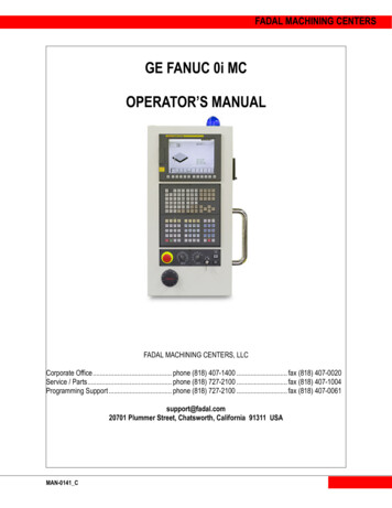
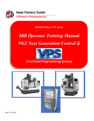
NGA Control DisplayActive G CodesProgram DisplayMode BarTool InfoMain Display PanelCoolant LevelInput BarSpindle and Feed StatusOverride StatusSpindle LoadIcon BarAxis Servo LoadsAbove is a view of the control panel in Memory Mode with the Program Key active on the Display Key.The Main Display Panel varies according to which of the DISPLAY keys are active.Productivity Inc – Haas CNC Mill Operator Manual – NG2 – 12/27/18Page 22
Keyboard IntroductionThe keyboard is divided into eight different sectors: Function Keys, Jog Keys, Override Keys,Display Keys, Cursor Keys, Alpha Keys, Number Keys and Mode Keys. In addition, there aremiscellaneous keys and features located on the pendant and keyboard which are described brieflyon the following pages.5-Cursor Keys1-Function Keys8-Mode Keys4-Display Keys2-Jog Keys3-Override6-Alpha KeysProductivity Inc – Haas CNC Mill Operator Manual – NG2 – 12/27/187-Number KeysPage 23
Next Generation Keyboard ChangesOnly four keys have been changed on the keyboard with the NGA ControlThe [DRY RUN] KEY has been changed to the [GRAPHICS] KEY.The NGC does not provide the Dry Run option as in older controls.The [ORIENT SPINDLE] KEY has been changed to the [HANDLE SCROLL] KEY.This allows the handle jog wheel to be used to scroll thru offsets or a program.If you want to orient the spindle, the M19 command must be run in the MDI mode.The [SEND] AND [REC] KEYS have been changed to FORWARD and BACK KEYS.These keys allow navigation forward and backward thru page history.NGC does not provide for a RS232 port.Only Ethernet connections are available or an upgrade to WIFI.Productivity Inc – Haas CNC Mill Operator Manual – NG2 – 12/27/18Page 24
Display KeysDisplay keys determine what is shown in the Main Display Panel.Below the [POSIT] Display Key is active in the Memory Mode.Tabs highlighted in orange tell you what axis you will see. Below the All tab is active.Machinist’s when they are setting up like to have the All tab highlighted. It shows where they are atwith respect the part zero. Also the distance is it going to go before the next block.By depressing the [ALTER] key the display may be customized as shown below:Productivity Inc – Haas CNC Mill Operator Manual – NG2 – 12/27/18Page 25
The [Offset Key] is active below.Tool Length Geometry values are shown along with Tool Diameter. If tool life management is beingused red will indicate the tool life has expired, yellow is a warning. Also Wear values may be enteredfor H(Length) and D(Tool Diameter).Productivity Inc – Haas CNC Mill Operator Manual – NG2 – 12/27/18Page 26
Cursor to the right gives a 2nd page Information on tool type, material and category may be entered.Cursor to the right again will give a probing page. On the far right different tool probing options can beselected. The information needed for probing is entered and probing may be performed from theoffsets page.Productivity Inc – Haas CNC Mill Operator Manual – NG2 – 12/27/18Page 27
Going back to the first offset page curser to the top to highlight Tool. Then highlight Work. This opensthe work offsets page as below.One may also toggle between work and tool offsets pages by using the [F4] key.Productivity Inc – Haas CNC Mill Operator Manual – NG2 – 12/27/18Page 28
[Current Commands] key gives many different options. Note the Timers tab is highlighted. On this pagecurrent date and time, cycle time, M30 counters for keeping track of the number of parts and Macrovalues may be indicated. One may cursor down into the page to reset the M30 counter by pressing the[ORIGIN] key.[Macro Vars] key gives the values of different variables # used in Macro Programming. Note 10000must be added to the old legacy numbers to find the equivalent variable. Variable #188 becomes#10188. Once inside the variable table the variable # needed can be keyed in and the down cursor keywill do a search for the particular variable.Productivity Inc – Haas CNC Mill Operator Manual – NG2 – 12/27/18Page 29
Highlighting the Active Codes tab gives the below panel. It may be used for trouble shooting aprogram. All current alphabet address codes are shown with their values. Below the T and M values are1000.This indicates that the machine is using ATM (Advanced Tool Management).With the ATM tab highlighted the Advanced Tool Management panel is shown below. To use first a1000 group must be set up and how the tool is managed (below the number of holes drilled is used).The [F4] key is used to switch boxes to denote the tools being used. Below Tools 5, 6 and 7 are used.Productivity Inc – Haas CNC Mill Operator Manual – NG2 – 12/27/18Page 30
Highlighting the Tool Table tab shows which tools are in which pockets.With side mount tool c
"CNC" (Computerized Numerical Control) is the same type of operating system, with the exception that a computer monitors the machine tool. The same principles used in operating a manual machine are used in programming a NC or CNC Machine. The main difference is that instead of