Transcription
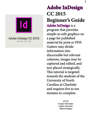
S P E C T R O S C O P YTUTORIALA Beginner’s Guide to ICP-MSPart II: The Sample-Introduction SystemROBERT THOMASPart II of Robert Thomas’ series on inductively coupled plasma mass spectrometrylooks at one of the most critical areas of theinstrument — the sample introduction system. He discusses the fundamental principles of converting a liquid into a finedroplet aerosol suitable for ionization inthe plasma, and provides an overview ofthe different types of commercially available nebulizers and spray chambers.The majority of inductively coupledplasma mass spectrometry (ICPMS) applications involve the analysisof liquid samples. Even though spectroscopists adapted the techniqueover the years to handle solids, it was developed in the early 1980s primarily to analyze solutions. There are many ways ofintroducing a liquid into an ICP massspectrometer, but they all basicallyachieve the same result — they generatea fine aerosol of the sample so it can beefficiently ionized in the plasma discharge. The sample-introduction area hasbeen called the Achilles heel of ICP-MSbecause it is considered the weakestcomponent of the instrument, with only1–2% of the sample finding its way intothe plasma (1). Although there has recently been much improvement in thisarea, the fundamental design of an ICPMS sample introduction system has notdramatically changed since the techniquewas first introduced in 1983.Before discussing the mechanics ofaerosol generation in greater detail, let uslook at the basic components of a sampleintroduction system. Figure 1 shows theproximity of the sample introduction arearelative to the rest of the ICP mass spectrometer, while Figure 2 represents theindividual components.The mechanism of introducing a liquidsample into analytical plasma can be considered as two separate events — aerosol56 SPECTROSCOPY 16(5)MAY 2001Figure 1. ICP-MS system diagram showing the location of the sample introduction area.generation using a nebulizer and dropletselection by way of a spray chamber.Sharp carried out a thorough investigation of both processes (2).AEROSOL GENERATIONAs mentioned previously, the main function of the sample introduction system isto generate a fine aerosol of the sample. Itachieves this purpose with a nebulizerand a spray chamber. The sample is normally pumped at 1 mL/min via a peristaltic pump into the nebulizer. A peristaltic pump is a small pump with lots ofminirollers that rotate at the same speed.The constant motion and pressure of therollers on the pump tubing feed the sample to the nebulizer. The benefit of a peristaltic pump is that it ensures a constantflow of liquid, irrespective of differencesin viscosity between samples, standards,and blanks. After the sample enters thenebulizer, the liquid is broken up into afine aerosol by the pneumatic action ofgas flow ( 1 L/min) smashing the liquidinto tiny droplets, which is very similar tothe spray mechanism of a can of deodorant. Although pumping the sample is themost common approach to introducing it,some pneumatic nebulizers, such as theconcentric design, don’t need a pump because they rely on the natural venturi effect of the positive pressure of the nebulizer gas to suck the sample through thetubing. Solution nebulization is conceptually represented in Figure 3, which showsaerosol generation using a nebulizer witha crossflow design.DROPLET SELECTIONBecause the plasma discharge is inefficient at dissociating large droplets, thespray chamber’s function is primarily toallow only the small droplets to enter theplasma. Its secondary purpose is tosmooth out pulses that occur during thenebulization process, due mainly to theperistaltic pump. Several ways exist to enw w w. s p e c t r o s c o p y o n l i n e . c o m
.sure only the small droplets get through,but the most common way is to use adouble-pass spray chamber where theaerosol emerges from the nebulizer andis directed into a central tube running thewhole length of the chamber. Thedroplets travel the length of this tube,where the large droplets (greater than 10 µm in diameter) fall out by gravityand exit through the drain tube at the endof the spray chamber. The fine droplets( 5–10 µm in diameter) then pass between the outer wall and the central tube,where they eventually emerge from thespray chamber and are transported intothe sample injector of the plasma torch(3). Although many different designs areavailable, the spray chamber’s main function is to allow only the smallest dropletsinto the plasma for dissociation, atomization, and finally ionization of the sample’selemental components. Figure 4 presentsa simplified schematic of this process.Let us now look at the different nebulizer and spray chamber designs that aremost commonly used in ICP-MS. This article cannot cover every type available because a huge market has developed overthe past few years for application-specificcustomized sample introduction components. This market created an industry ofsmall OEM (original equipment manufacturers) companies that manufacture partsfor instrument companies as well as selling directly to ICP-MS users.NEBULIZERSBy far the most common design used forICP-MS is the pneumatic nebulizer,which uses mechanical forces of a gasflow (normally argon at a pressure of20–30 psi) to generate the sampleaerosol. The most popular designs ofpneumatic nebulizers include concentric,microconcentric, microflow, and crossflow. They are usually made from glass,but other nebulizer materials, such asvarious kinds of polymers, are becomingmore popular, particularly for highly corrosive samples and specialized applications. I want to emphasize at this pointthat nebulizers designed for use with ICPoptical emission spectroscopy (OES) arenot recommended for ICP-MS. This factresults from a limitation in total dissolvedsolids (TDS) that can be put into the ICPMS interface area. Because the orificesizes of the sampler and skimmer conesused in ICP-MS are so small ( 0.6–1.2mm), the concentration of matrix components must generally be kept below 0.2%SPECTROSCOPY TUTORIAL.Figure 3. Conceptual representation ofaerosol generation with an ICP-MSnebulizer.Figure 2. Diagram of the ICP-MS sampleintroduction area.(4). Therefore, general-purpose ICP-OESnebulizers that are designed to aspirate1–2% dissolved solids, or high-solids nebulizers such as the Babbington, V-groove,or cone-spray nebulizers, which are designed to handle as much as 20% dissolved solids, are not ideal for use withICP-MS. The most common of the pneumatic nebulizers used in commercial ICPmass spectrometers are the concentricand crossflow designs. The concentric design is more suitable for clean samples,while the crossflow is generally more tolerant to samples containing higher levelsof solids or particulate matter.Concentric design. In the concentric nebulizer, the solution is introduced througha capillary tube to a low-pressure regioncreated by a gas flowing rapidly past theend of the capillary. The low pressure andhigh-speed gas combine to break up thesolution into an aerosol, which forms atthe open end of the nebulizer tip. Figure5 illustrates the concentric design.Concentric pneumatic nebulizers canprovide excellent sensitivity and stability,particularly with clean solutions. However, the small orifices can be plagued byblockage problems, especially if largenumbers of heavy matrix samples areaspirated.Crossflow design. For samples that contain a heavier matrix or small amounts ofundissolved matter, the crossflow designis probably the best option. With this design the argon gas is directed at right angles to the tip of a capillary tube, in contrast to the concentric design, where thegas flow is parallel to the capillary. Thesolution is either drawn up through thecapillary tube via the pressure created bythe high-speed gas flow or, as is mostFigure 4. Simplified representation of theseparation of large and fine droplets in thespray chamber.common with crossflow nebulizers,forced through the tube with a peristalticpump. In either case, contact between thehigh-speed gas and the liquid streamcauses the liquid to break up into anaerosol. Crossflow nebulizers are generally not as efficient as concentric nebulizers at creating the very small dropletsneeded for ICP-MS analyses. However,the larger diameter liquid capillary andlonger distance between liquid and gasinjectors reduce clogging problems.Many analysts feel that the small penaltypaid in analytical sensitivity and precisionwhen compared with concentric nebulizers is compensated by the fact that thecrossflow design is far more rugged forroutine use. Figure 6 shows a cross section of a crossflow nebulizer.Microflow design. A new breed of nebulizers is being developed for ICP-MScalled microflow nebulizers, which aredesigned to operate at much lower sample flows. While conventional nebulizershave a sample uptake rate of about1 mL/min, microflow nebulizers typicallyrun at less than 0.1 mL/min. They arebased on the concentric principle, butMAY 200116(5) SPECTROSCOPY 57
.SPECTROSCOPY TUTORIALFigure 5. Diagram of a typical concentric nebulizer.Figure 7. A typical concentric microflownebulizer. Printed with permission from Elemental Scientific (Omaha, NE).they usually operate at higher gas pressure to accommodate the lower sampleflow rates. The extremely low uptake ratemakes them ideal for applications withlimited sample volume or where the sample or analyte is prone to sample introduction memory effects. These nebulizers and their components are typically.Figure 6. Schematic of a crossflow nebulizer.constructed from polymer materials suchas polytetrafluoroethylene (PTFE), perfluoroalkoxy (PFA), or polyvinylidene fluoride (PVDF). In fact, their excellent corrosion resistance means that they havenaturally low blank levels. This characteristic, together with their ability to handlesmall sample volumes such as vaporphase decomposition (VPD) applications,makes them an ideal choice for semiconductor labs that are carrying out ultratrace element analysis (5). A typical microflow nebulizer made from PFA isshown in Figure 7.SPRAY CHAMBERSLet us now turn our attention to spraychambers. Basically two designs are usedin commercial ICP-MS instrumentation— double pass and cyclonic spray chambers. The double pass is by far the mostcommon, with the cyclonic type gainingin popularity. Another type of spray chamber based on the impact bead design(first developed for flame AA and thenadapted for ICP-OES) was tried on theearly ICP-MS systems with limited success, but is not generally used today. Asmentioned earlier, the function of thespray chamber is to reject the largeraerosol droplets and also to smooth outpulses produced by the peristaltic pump.In addition, some ICP-MS spray chambers are externally cooled (typically to2–5 C) for thermal stability of the sample and to minimize the amount of solventgoing into the plasma. This can have anumber of beneficial effects, dependingon the application, but the main benefitsare reduction of oxide species and theability to aspirate volatile organicsolvents.Figure 9. Schematic of a cyclonic spray chamber (shown withconcentric nebulizer).Figure 8. Schematic of a Scott double-pass spray chamber (shownwith crossflow nebulizer). Printed with permission of PerkinElmerInstruments (Norwalk, CT).58 SPECTROSCOPY 16(5)MAY 2001w w w. s p e c t r o s c o p y o n l i n e . c o m
.Double pass. By far the most commondesign of double-pass spray chamber isthe Scott design, which selects the smalldroplets by directing the aerosol into acentral tube. The larger droplets emergefrom the tube and, by gravity, exit thespray chamber via a drain tube. The liquid in the drain tube is kept at positivepressure (usually by way of a loop),which forces the small droplets back between the outer wall and the central tube,where they emerge from the spray chamber into the sample injector of the plasmatorch. Scott double-pass spray chamberscome in a variety of shapes, sizes, andmaterials, but are generally consideredthe most rugged design for routine use.Figure 8 shows a Scott spray chambermade of a polysulfide-type material, coupled to a crossflow nebulizer.Cyclonic spray chamber. The cyclonicspray chamber operates by centrifugalforce. Droplets are discriminated according to their size by means of a vortex produced by the tangential flow of the sample aerosol and argon gas inside thechamber. Smaller droplets are carriedSPECTROSCOPY TUTORIAL.with the gas stream into the ICP-MS,while the larger droplets impinge on thewalls and fall out through the drain. It isgenerally accepted that a cyclonic spraychamber has a higher sampling efficiency, which, for clean samples, translates into higher sensitivity and lower detection limits. However, the droplet sizedistribution appears to be different from adouble-pass design, and for certain typesof samples, can give slightly inferior precision. An excellent evaluation of the capabilities of a cyclonic spray chamber wasmade by Beres and co-workers (6). Figure 9 shows a cyclonic spray chamberconnected to a concentric nebulizer.Many other nonstandard sample introduction devices are available that are notdescribed in this particular tutorial, suchas ultrasonic nebulization, membrane desolvation, flow injection, direct injection,electrothermal vaporization, and laser ablation. However, they are becoming moreand more important, particularly as ICPMS users are demanding higher performance and more flexibility. For that reason, they will be addressed in a separatetutorial at the end of this series.REFERENCES(1) R. A. Browner and A.W. Boorn, Anal.Chem. 56, 786–798A (1984).(2) B.L. Sharp, Analytical Atomic Spectrometry 3, 613 (1980).(3) L.C. Bates and J.W. Olesik, Journal of Analytical Atomic Spectrometry 5(3), 239(1990).(4) R.S. Houk, Anal. Chem. 56, 97A (1986).(5) E. Debrah, S. A. Beres, T.J. Gluodennis,R.J. Thomas, and E.R. Denoyer, AtomicSpectroscopy, 197–202 (September 1995).(6) S. A. Beres, P. H. Bruckner, and E.R. Denoyer, Atomic Spectroscopy, 96–99(March/April 1994).Robert Thomas is the principal of his ownfreelance writing and scientific marketingconsulting company, Scientific Solutions,based in Gaithersburg, MD. He specializesin trace element analysis and can be contacted by e-mail at thomasrj@bellatlantic.net or via his web site at www.scientificsolutions1.com. “News Spectrum” continued from page 13TRAINING COURSESThermo Nicolet (Madison, WI) is offering afree Spring 2001 Spectroscopic SolutionsSeminar Series. The seminars will coverbasic FT-IR spectroscopy, microspectroscopy, dispersive Raman microscopy,Raman spectroscopy, and specializedsampling techniques. This year’s schedule includes the following seminars:May 22 at the Syracuse Sheraton,Syracuse, NY; May 24 at the Wyndham Westborough Hotel, Westborough, MA; May 24 at the MarriottOak Brook, Oak Brook, IL; June 5 atthe East Lansing Marriott, East Lansing, MI; June 5 at the Embassy Suites,Overland Park, KS; June 7 at the Sheraton Indianapolis, Indianapolis, IN;June 12 at the Delta MeadowvaleConference Center, Mississauga,Ontario, Canada; June 12 at the Embassy Suites, Brookfield, WI; July 10at the Coast Terrace Inn, Edmonton,Alberta, Canada; and July 26 at the AlaMoana Hotel, Honolulu, HI.For more information, contact ThermoNicolet, (800) 201-8132 fax: (608) 2735046, e-mail: nicinfo@thermonicolet.com, web site: www.thermonicolet.com. 60 SPECTROSCOPY 16(5)Circle 51MAY 2001w w w. s p e c t r o s c o p y o n l i n e . c o m
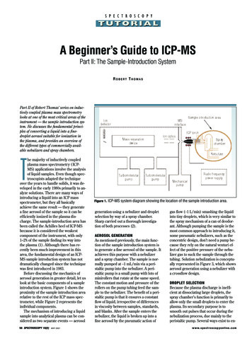
S P E C T R O S C O P YTUTORIALA Beginner’s Guide to ICP-MSPart III: The Plasma SourceROBERT THOMASPart III of Robert Thomas’ series on inductively coupled plasma–mass spectroscopy( ICP-MS) looks at the area where the ionsare generated — the plasma discharge. Hegives a brief historical perspective of someof the common analytical plasmas usedover the years and discusses the components that are used to create the ICP. Hefinishes by explaining the fundamentalprinciples of formation of a plasma discharge and how it is used to convert thesample aerosol into a stream of positivelycharged ions.Inductively coupled plasmas are by farthe most common type of plasmasources used in today’s commercialICP–optical emission spectrometry(OES) and ICP-MS instrumentation.However, it wasn’t always that way. In theearly days, when researchers were attempting to find the ideal plasma sourceto use for spectrometric studies, it wasunclear which approach would prove tobe the most successful. In addition toICPs, some of the other novel plasmasources developed were direct currentplasmas (DCP) and microwave-inducedplasmas (MIP). A DCP is formed when agas (usually argon) is introduced into ahigh current flowing between two orthree electrodes. Ionization of the gasproduces an inverted Y-shaped plasma.Unfortunately, early DCP instrumentation was prone to interference effects andalso had some usability and reliabilityproblems. For these reasons, the technique never became widely accepted bythe analytical community (1). However,its one major benefit was that it could aspirate high levels of dissolved or suspended solids, because there was no restrictive sample injector for the solidmaterial to block. This feature alonemade it attractive for some laboratories,and once the initial limitations of DCPs26 SPECTROSCOPY 16(6)JUNE 2001MSinterfaceIondetectorICP torchIon opticsSpraychamberMass separationdeviceNebulizerRadio frequencypower alpumpFigure 1. Schematic of an ICP-MS system showing the location of the plasma torch and radiofrequency (RF) power supply.were better understood, the techniquebecame more accepted. In fact, for thosewho want a DCP excitation source coupled with an optical emission instrumenttoday, an Echelle-based grating using asolid-state detector is commerciallyavailable (2).Limitations in the DCP approach led tothe development of electrodeless plasma,of which the MIP was the simplest form.In this system, microwave energy (typically 100–200 W) is supplied to the plasmagas from an excitation cavity around aglass or quartz tube. The plasma discharge in the form of a ring is generatedinside the tube. Unfortunately, eventhough the discharge achieves a veryhigh power density, the high excitationtemperatures exist only along a central filament. The bulk of the MIP never getshotter than 2000–3000 K, which means itis prone to very severe matrix effects. Inaddition, they are easily extinguished dur-ing aspiration of liquid samples. For thesereasons, they have had limited success asan emission source, because they are notconsidered robust enough for the analysisof real-world, solution-based samples.However, they have gained acceptance asan ion source for mass spectrometry (3)and also as emission-based detectors forgas chromatography.Because of the limitations of the DCPand MIP approaches, ICPs became thedominant focus of research for both optical emission and mass spectrometricstudies. As early as 1964, Greenfield andco-workers reported that an atmosphericpressure ICP coupled with OES could beused for elemental analysis (4). Althoughcrude by today’s standards, the systemshowed the enormous possibilities of theICP as an excitation source and most definitely opened the door in the early 1980sto the even more exciting potential of using the ICP to generate ions (5).w w w. s p e c t r o s c o p y o n l i n e . c o m
arygasSPECTROSCOPY TUTORIAL(a)Quartztorch.(b)Nebulizer gasSample injectorRFcoilRF powerFigure 2. Detailed view of a plasma torchand RF coil relative to the ICP-MS interface.Figure 3. (right) Schematic of an ICP torchand load coil showing how the inductivelycoupled plasma is formed. (a) A tangentialflow of argon gas
he majority of inductively coupledplasma mass spectrometry (ICP-MS) applications involve the analysis of liquid samples. Even though spec-troscopists adapted the technique over the years to handle solids, it was de-veloped in the early 1980s primarily to an-alyze solutions. There are many ways