Transcription
Struct Multidisc Optim (2010) 41:621–635DOI 10.1007/s00158-009-0435-8INDUSTRIAL APPLICATIONMultidisciplinary optimization of injection molding systemsIrene Ferreira · Olivier de Weck ·Pedro Saraiva · José CabralReceived: 11 September 2008 / Revised: 4 August 2009 / Accepted: 25 August 2009 / Published online: 6 October 2009c Springer-Verlag 2009 Abstract The design of injection molding systems for plastic parts relies heavily on experience and intuition. Recently,mold makers have been compelled to shorten lead times,reduce costs and improve process performance due to globalcompetition. This paper presents a framework, based on aMultidisciplinary Design Optimization (MDO) methodology, which tackles the design of an injection mold by integrating the structural, feeding, ejection and heat-exchangesub-systems to achieve significant improvements. To validate it single objective optimization is presented leadingto a 42% reduction in cycle time. We also perform multiple objective optimization simultaneously minimizing cycletime, wasted material and pressure drop. Sensitivity analysisshows a large impact of the sprue diameter ( 1.5 normalized sensitivity) highlighting the importance of the feedingsubsystem on overall quality. The results show substantialimprovements resulting in reduced rework and time savingsfor the entire mold design process.Nomenclatured Spr uel Runnerl GatedGateα Spr uel Spr uePin jdRunnern Ramifn downstreamn GatedReleaseαAprojSprue diameter [m]Runner length [m]Gate length [m]Gate diameter [m]Sprue draft angle [ ]Sprue length [m]Injection pressure [Pa]Runner diameter [m]Number of ramifications of runnersNumber of ramification streamsNumber of gates’ points per partDistance of part’s release [m]Coefficient of diffusitivity [m2 /s]Projected area of molded part [m2 ]1 IntroductionKeywords Injection mold design · MDO ·Global design · Cycle timeI. Ferreira (B) · O. de WeckEngineering Systems Division (ESD),Massachusetts Institute of Technology,Cambridge, MA 02139, USAe-mail: iferreira@estg.ipleiria.ptP. SaraivaChemical Engineering Department, University of Coimbra,Coimbra, PortugalJ. CabralEngineering Faculty, University of Porto, Porto, PortugalAn injection mold is a high precision tool required for theproduction of plastic parts. Its main purpose is to replicatethe desired geometry of the final plastic part by transformingmolten plastic into its final shape and dimensional details.Currently, the design of an injection mold is a highly interactive and manual process involving substantial knowledgeof multiple areas, such as mold design features, mold making processes, molding equipment and part design, all ofwhich are highly coupled to each other. The main challenge is to design and produce a mold that is straightforwardto manufacture, while providing uniform filling and cooling of plastic parts. At the same time the tool has to bestrong enough to withstand millions of cyclic internal loadsfrom injection pressures and external clamp pressures, inorder to assure the target part’s reproducibility (Beaumont
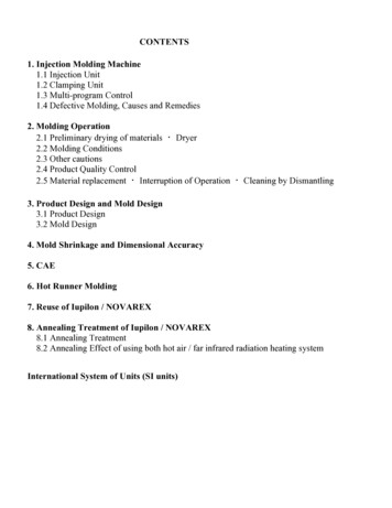
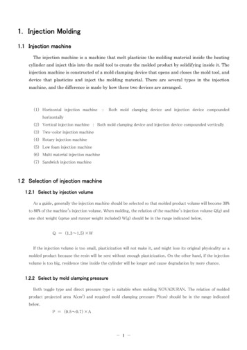
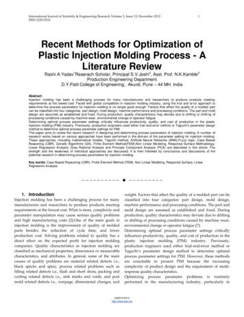
622I. Ferreira et al.Fig. 1 Typical halves of aninjection mold: cavity (left) andcore (right) (Centimfe 2000)et al. 2002). In this sense, an injection mold can be seenas a mechanical structure with some functional subsystems,such as the feeding system, heat-transfer system, structuralsystem and ejection system. Usually, this structure is composed of two halves, where the top half of the mold iscommonly referred to as the cavity half or the fixed half ofthe mold. The bottom half is known as the core or movablehalf (Fig. 1). In some cases, the cavity and core halves canbe switched.It is common for the cavity to be machined directly inthe cavity inserts (dark elements), but sometimes it includesan injection clamping and a cavity retainer plate (Fig. 2). Inless demanding cases, the cavity is machined directly into acavity plate, which avoids the use of the retainer plate. Thepath for the melt (liquid plastic) to travel from the injectionmachine to the parting line is defined by a sprue brushing,which may feed directly a cavity (at a single gate point), ora runner in a multi-cavity (more than one part injected foreach injection cycle) or a multi-gates point part (more thanone gate point per part). During mold opening—for coldrunner systems—the plastic sprue and runners are pulledfrom the sprue bushing by the ejection system, while forhot runner systems, the runners stay molten and are ejectedduring the molding cycle.Typically, the other half of the mold contains the core andthe ejection system. The core usually refers to the portionof the two mold halves where there are protrusions, ontowhich the forming plastic part will shrink and to which itwill adhere during mold opening. The part is then usuallypushed off the core by a mechanical ejection system. Inorder to release the part after cooling, some space is normally provided to allow movement (ejector stroke) of theejector plates to which ejector pins are attached. This backand forth movement is assured by a hydraulic cylinder toItem1237891216232526293032DesignationInjection clamping plateCavity retainer plateCore retainer plateEjector pin plateEjector pin retainer plateE jection clamping plateSupport pillarLeader pinEjector plate pinGuide bushingCentering sleeveEjector plate bushingReturn pinLocating ringFig. 2 Cross-sectional view of a common mold assembly (Vasco et al. 2007 with authors’ 484511DesignationLocating ringSprue bushingMainfoldK.O.Cavity insertSub-insertCavity insertCore insertJinggle pinJinggle pin rodMold floor supportInsulator plateEjector protection plate
Multidisciplinary optimization of injection molding systemswhich the ejector plate is attached. Based on this cycle, themain components of a typical injection mold, and respectivefunctions, are as follows:623Table 1 Subsystems andobjective functions for injectionmold designSystemInjectionmoldGlobal objectivesMin cycle timeMin costSubsystem Local objectives(a) Feeding System (including the venting system). Itsmain function is to channel the molten plastic material coming from the injection nozzle of the moldingmachine and distribute it into each cavity, through therunners and respective gate points. Generally, injection molds can be classified as either “cold runner” or“hot runner” molds. A cold runner refers to a moldin which the feeding system is cooled, solidified andejected with the molded part in each molding cycle. Inthe case of a hot runner mold, the runner is kept in amolten state, avoiding a runner that must be refilledand discarded in each cycle. The hot runner systemis typically composed of two components: the manifold and the drop(s). The venting subsystem mustallow for gas release, because when the melt entersinto the cavity the displaced air must have a meansto escape. The design of this subsystem depends onthe part’s geometry, its position in the mold and itsgating;(b) Heat-transfer System. It supplies the mold with a system of cooling channels, through which a coolant ispumped. Usually, its main function is to remove heatfrom the mold, so that—once filled—the part is sufficiently rigid to be demolded. Note that given the fastcycle time of most machines that the coolant flow iscontinuous and thus some amount of heat evacuationis always ongoing;(c) Ejection System. Its main function is to knock outthe injection molded parts, in order to release themfrom the mold. Typically, after the mold is opened, thehydraulic cylinder of the injection machine will actuate the ejection system to move forward, pushing themolded parts out. It is critical that the ejection systemdoes not cause damage (marks) to completed parts;(d) Structural System. It must allow the mold (tool) to becoupled into the injection machine and assure the overall assembly of its components. It is also necessaryto guarantee the alignment and guiding of the mold.According to the type of mold, it involves several metalplates to form a rigid body where some components areassembled together (e.g. locating ring; guide pins andguide bushings, amongst others);(e) Others: for complex plastic parts, some other mechanisms, such as slides, lifters, unscrewing devices,amongst others, might also be necessary.Therefore, the mold design optimization must encompass the optimization of four main highly-coupled systems,FeedingMin volumeMin pressure dropHeat-Max heat transferexchangeEjectionMin marksStructuralMin bendingMin deflectionnamely the Structural, Feeding, Heat-Exchange and Ejection systems, where each one is characterized by one ormore local objective functions, in order to assure satisfaction of both final part and manufacturing processrequirements. Globally, the mold as a system involves theoptimization of two main functions, namely the mold’s costand performance (Table 1). At this stage, the mold’s performance will be evaluated by its cycle time. The cycle time isdefined as the time required from initial injection of a part,through cooling and ejection to the point where the next partis ready to be injected. It is the major attribute of injectionmolding productivity. Part tolerances and uniformity are setas constraints.2 Related researchThe design of an injection mold is considered criticallyimportant to product quality and efficient processing, aswell as a determining factor for the economics of the entireprocess (Chan et al. 2003; Low 2003). In this sense, andin order to achieve high levels of product quality in lesstime, both academia and industry have been looking for newmethods to address mold design. Therefore, a lot of scientific research has been done on mold design and its relatedfields over the last years, mostly on Knowledge-Based (KB)methods (this approach is justified by the extensive empirical knowledge about mold component functions). Examples of work in this area are IKB-MOULD (Mok et al.2001), a 3D CAD KB (Chan et al. 2003) and ESMOLD(Chin and Wong 1996). According to Chan et al. (2003),one emergent area of research in the injection molding fieldattempts to generate automatically the design of mold toolcomponents. Although, due to high complexity and significant mold component interactions, some authors (Chanet al. 2003; Low 2003) consider this approach not to befeasible for the automatic generation of an entire injection mold. Thus, this new approach has been used only tosolve particular aspects of mold design. As examples of this
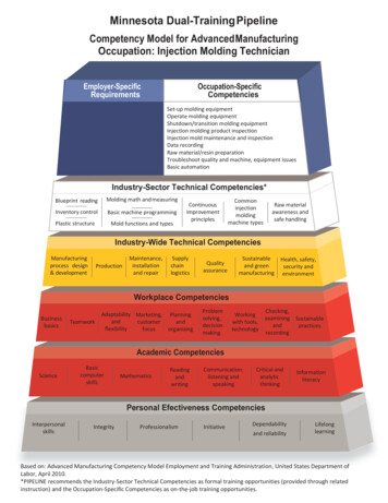
624I. Ferreira et al.research thrust, Mehnen et al. (2004) studied the automation of Heat-Exchange subsystem design while Lam et al.(2004b) pursued a multi-objective approach with integrationof Genetic Algorithms and CAE. On the subject of optimal feeding subsystems, Lee and Lin (2006) used FEM,Taguchi’s method and an abductive network to select thebest parameters. Lam et al. (2004a) proposed an automatedgate optimization routine and Shen et al. (2004) developeda modified hill-climbing algorithm in order to determine thebest gate location. These examples highlight the fact thatresearch in injection mold design optimization is underway,but generally involves only one particular aspect of the totaldesign. In our opinion the inexistence of a mold’s subsystemintegration (which points out the coupled relations) and theinadequate exploration of the feasible design space are limitations that must be overcome. In this sense, it is importantto optimize the mold as a system through integration of itsmain subsystems.3 Proposed approachCurrently, due to market pressure to reduce the time-tomarket of products, the lead-time available for designingand making injection molds is decreasing. Rather than taking several months, mold design must now be accomplishedin a matter of 2–4 weeks, depending on part complexity.Additionally, during the mold design process, customersoftentimes impose several changes to the plastic part geometry and other attributes, requiring fast modifications of themold. Therefore, molds makers are compelled to shortenboth lead times and cost, as well to accomplish higher levels of mold performance. This will only be possible withnew design approaches. For all the reasons previously mentioned, a framework based on MDO, that aims to optimizethe mold design as a system, was developed. The maindesign loop of the developed framework, where processintegration is made by blocks representing its individualmodules (Fig. 3), starts with a geometrical configurationof the initial mold solution, designed according to bestpractice guidelines. Then, the Geometry handler modulecalculates the geometrical and physical dimensions thatwill be used in the following steps and creates the Parasolid file needed by the subsequent analysis. Phenomenaanalyses are, at this stage, carried out by some analysiscodes that use simplified mathematical models to characterize the main injection molding modules: the Structural, theSubsystem characteristicsCycle time, Vfeed, Pressure,Deflection, MarksInitial/Old subsystemsgeometryMold costDesign loopNew subsystems geometry(parasolid, meshing)Subsystemscharacteristics, Mold sizeFeedingsubsystemHeatexchangesubsystemThermal and Rheological(Simplified vs high-fidelity models)Cycle time, Vfeed, PressureFig. 3 Framework process integrationStructural subsystemEjection subsystemStructuralMechanicalDeflection, Mold sizeMarks
Multidisciplinary optimization of injection molding systemsSymbolDesignationSymbol6251.5 typeRunnerPosition of molding on thepartition planeType of runner3.2l SprueDesignationFinal distance on X coordinate4.1for plate iFinal distance on Y coordinate4.2for plate iDistance on X coordinate of4.3cavity insertDistance on Y coordinate of4.4cavity insertLength of sprue4.51.6 TmoldTemperature of mold3.3d SprueDiameter of sprue4.6Zcool1.7 PartlineParting line3.6d RunnerDiameter of runner4.7Pitchcool3.7l RunnerLength of runner5.1nPinsNumber of ejection elements3.8typeGate Type of gate5.2(x,y)pPosition of ejection element p3.9d Gate5.3dPinsDiameter of ejection element1.1 t injTime of injection2.20 X i1.2 PinjInjection pressure2.21 Yi1.3 typeMold1.4 Positionmolding2.1 Xmold2.2 Ymold2.4 nplates2.5 Zi2.18 l Ret2.19 dRetType of moldDistance of mold on XcoordinateDistance mold on YcoordinateNumber of platesFinal distance on Zcoordinatefor plate iLenght of return elementsDiameter of return elementsFig. 4 Block diagram for injection mold modules2.22 InsX2.23 InsYDiameter of gateSymbol(x0,y0)cDesignationInitial Coordinates line i(xh,yh) cFinal Coordinates line inturnsNumber of changes inposition of cooling channelncoolNumber of cooling channelsdcoolDiameter of cooling channelDistance on Z from cavitysurface to the center ofcooling linePitch betwen coolingchannels3.10 l GateLength gate5.5l PinsLength of ejection element3.11 (x,y,z)g3.12 n GatesPosition of each gateNumber of gates5.6dReleaseDistance of part’s release
626Feeding, the Ejection and the Heat-Exchange subsystems.Later, as future research, these phenomena will be model bymore accurate and realistic approximations through the integration of high-fidelity numerical models (e.g. Moldflowcode—www.moldflow.com).The system level of this framework involves the initialdesign decisions, such as type of mold, type of feedingsystem, etc. and the integration of the functional modules as interlinked subsystems. The respective inputs andoutputs of each module were determined (Fig. 4), and ablock diagram was built in order to identify the feedforward and feedback paths between the different modules. Itis important to note that the mapping is generic and wasestablished independently of specific plastic part and injection machine characteristics (i.e. these modules and theirrelations are present in every mold design problem). Thisapproach allows the mathematical formulation of the molddesign as a multidisciplinary system design problem. Themultidisciplinary processes considered were rheological,which seeks to model and evaluate the mold filling process, thermal, encompassing heat transfer, mechanical,concerning the mold’s physical movements, and, finally,structural (mainly represented by the number of plates anddimensions of each plate) aiming to minimize the mold’sdeformation induced by compressive and bending stresses.Some assumptions have been made to simplify this MDOapproach to injection mold design. For example, issues likethe spatial collisions between some of the mold’s elements(e.g. pins, cooling lines, fixing elements, venting, amongstothers), as well as the design of more complex elements, likeslides and lifters, have not been taken into account. Also, areliable cost model (both for design and tool cost, as well aspart manufacturing cost) has not yet been developed. Forthis reason, at the present stage the mold design will beoptimized for minimum cycle time. In order to undertakea first multi-objective optimization, the cycle time, as welltwo local objectives, namely, the volume of feeding systemand the injection pressure drop, will be used as indicators ofthe mold’s performance.The cycle time is computed considering that the injectionmolding process has five main stages (Rosato et al. 2001).The first one, designated as Plasticizing (1), involves theheating and melting of the plastic in the plasticator. The second stage, Injection (2), encompasses a shot of melt into theclosed mold. The third stage, named Afterfilling or Packing (3), aims to prevent back flow and compensates for thedecrease in volume of melt during solidification. The fourth,the Cooling stage (4), involves the molded part coolingin the mold until it is sufficiently rigid to be ejected. Finally,the last stage, Release (5), allows removal of the part byhydraulically opening and closing the mold to start the nextcycle (Fig. 5).I. Ferreira et al.Fig. 5 Main stages of injection moldingBased on this assumption, the cycle time is calculatedas the sum of each of the stage times. However, plasticizing time (1) was not considered in cycle time computation,since it occurs simultaneously with the cooling and packingstages of the previous part. Regarding filling time (2), whichdepends mostly on process conditions, it was assumed asa reasonable imposed (user selected) value, similarly to themodeling procedure in Moldflow. This is a realistic assumption and allows comparison of solutions modeled by theproposed framework and verified by Moldflow.The cooling stage, which in fact begins with mold fillingand finishes when enough heat has been removed fromthe part in order to eject it without distortion, is the mostimportant stage, since it absorbs about 80% of the cycletime (Qiao 2006). The heat exchange between plastic andcoolant, which occurs at this stage through thermal conduction, can be described by Fourier’s differential equation(Menges et al. 2001). Since heat is mainly removed in onedirection (thickness direction), heat-transfer is usuallydescribed using a one dimensional description (Mengeset al. 2001; Kazmer 2007). Following this approach,Fourier’s differential equation can be reduced to: T 2T α 2 t z(1)where α is the thermal diffusitivity, T is the temperature,t is time and z is the thickness direction coordinate. Assuming that immediately after injection the melt temperature inthe cavity has a uniform constant value of Tmelt , and thatthe temperature of the cavity walls jumps abruptly to theconstant value Tcool , which remains constant, the cooling
Multidisciplinary optimization of injection molding systems627time (4) for a strip plane geometry can be estimated usingthe previous equation, leading to the following expression(Kazmer 2007):tcool s2π 2α ln8 (Tmelt Tcool )π 2 (Tdemol Tcool ) (2)where s is the wall thickness assuming the plastic part asa strip plate, Tmelt is the melting temperature, Tcool is thecavity wall temperature and Tdemol is the mean demoldingtemperature (the temperature at which the material is rigidenough to be ejected). Assuming that the time required forcooling the feeding system is longer than the time neededto cool the part itself (this is a necessary constraint toavoid premature freezing inside the part which could leadto incomplete filling), the bottleneck of the cooling process will be the feeding system, or more precisely the Sprue(biggest component of this subsystem, since it must supply the entire feeding system with enough melt). Due to theconical shape of this component (Menges et al. 2001), theprevious generic equation (1) must be replaced by: (Tmelt Tcool )ln 0.69223.1α(Tdemol Tcool )2tcool d Spr ue(3)where d Spr ue is the sprue mean diameter. Note that both (2)and (3) are solutions of (1), but (2) is valid for strip plates,while (3) assumes a cylindrical geometry.The post-filling time (3), generally known as packingtime, is determined based on the gate dimensions (Kazmer2007). The packing stage has as its main function to forceadditional melt into the cavity, after the filling stage, in orderto compensate for volumetric shrinkage of the part and toavoid any back flow of melt. Therefore, if the gate is toosmall the melt will prematurely solidify and no additionalmaterial will enter into the cavity (packing does not occur).If it is too large, the gate will take more time than necessary to solidify, which results in a longer pack time. Thus,the packing stage time must end with the gate freeze-off.The necessary cooling time for gates (i.e. gate freeze-off) isdetermined using an expression according to (4):t pack 2dGate(Tmelt Tcool )ln 0.692 23.1α(Tdemol Tcool )(4)where dGate is the gate diameter.The mold opening time is calculated as the ratio of themold opening distance (designated as d Release ) and the moldopening velocity. The velocity of mold opening (vopen ) wasbased on Kazmer’s regression (Kazmer 2007: page 129),which states that the velocity is a logarithmic function ofthe ratio between the clamping force (i.e. the force neededto hold the mold closed expressed in tons) and a referenceforce of 1 ton (5). vopen [mm/s] 184 13logFclampFr e f (5)Where vopen is expresses in millimeters per second. Sincethe clamping force can be computed as the injection pressure (Pin j ) times the projected area of molding (A pr oj ), themold opening time can be calculated using (6).topen d Release 1 103 P A proj 1 10 3184 13log in j 9.8Fref(6)In this work, it is assumed that the time to open is equalto the time to close the mold (i.e. the time to release the part(5) is equal to two times the opening time). In summary, thetheoretical cycle time (objective function), which involvesthe summation of cooling time (expressed by the necessarytime to cool the Sprue) plus the packing time (which is limited by gate’s freezing), and, finally, the time to open andto close the mold, that can be described by the followingexpression: α ue π 2l Spr ued Spr ue tan Spr180C ycle time 23.1α (Tmelt Tcool ) ln 0.692(Tdemol Tcool ) 2dgate(Tmelt Tcool ) ln 0.69223.1α(Tdemol Tcool ) 2 d Release 1 103 P A proj 1 10 3184 13log in j 9.8Fref(7)Considering Fig. 5 the plasticizing time (1) is neglectedsince it occurs in parallel with the other processes for thepreceding part. Also, the injection time (2) is very smallcompared to the other times in (7) and is assumed as a constant value (it was assumed 1.5 s for filing time). Finally,the cooling time (4) is not the total time doing which cooling occurs, but only the excess cooling time required for theSprue to freeze (Fig. 6).Note that d Spr ue can be determined based on the geometrical characteristics of the Sprue as:d Spr ue d Spr ue tan αSpr ue π180 l Spr ue(8)where d Spr ue is the initial diameter, l Spr ue is the length andα Spr ue is the draft angle.
628I. Ferreira et al.To optimize cycle time, the following constraints areconsidered: Pin j 32 l Spr ue l Runner l Gates l par t ϕv F ηae ff 0 22MaxY MintMaxY MintThe pressure demand to counter the resistance to flowin plate (flow length/wall thickness ratio derived fromHagen–Pouseuille’s law (Menges et al. 2001)).(9)Pin j The melt pressure acting in the projected area of moldcavities must not surpass the maximum clamp force(required to hold the mold closed during operation).Fclamp max 0A pr oj(10)To assure geometric feasibility, the length of Sprue mustbe equal to plate’s distance starting in injection nozzleuntil partition plane.(11)l Spr ue Z cav Z plate 1 0 dGate 2(3 1/n) V̇π γ̇max1/3 0Shear rate for flow in gates must not surpass the maximumallowable shear (Power law is assumed, which is aconservative approach).(12) d Release Max Open Z mold 0Distance of part’s release must not surpass the maximumfree open distance of mold.(13) d Release 2.5Max Z 0The distance of mold opening must assure part’s release.(14) d Spr ue d Runner n downstr eam 0Sprue must have enough capacity to fulfill all thedownstream runners.(15)where l Runner is the runner length, l Gates is the gates lengthand l par t is the part length, ϕ represents a constant ratiobetween width and thickness (which is equal to 1.5, whenwidth is much bigger than thickness), v̄ F is the velocity ofthe flow front and ηae ff is the apparent effective viscosity;MaxY and MaxZ are the part maximum distances along theReal coolingY and Z directions, respectively; Fclampmax is the maximumclamping force; Z cav , Z plate 1 and Z mold correspond to thedistance in the Z direction for the cavity plate, plate one andfor the complete mold, respectively; n is the power indexof the Power Law model, V̇ is the volumetric flow rate andγ̇max is the maximum shear rate for the plastic; MaxOpen isthe maximum distance in Z direction for the mold. The runner diameter is defined by d Runner and, finally, n downstr eamis the number of streams of each ramification. The designvariable bounds are defined as follows:Lower and upper bounds:Fig. 6 Timeline of each injection molding staged Spr ue 0.02(16)1 α Spr ue 4(17)
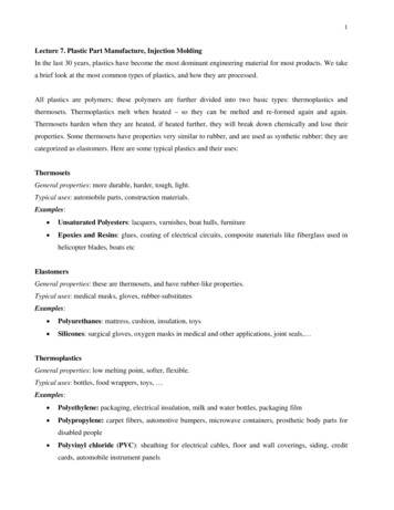
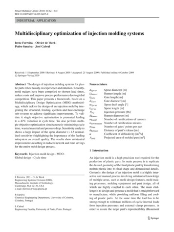
Multidisciplinary optimization of injection molding systems6290.0005 dGate 0.003(18)0.0005 l Gate 0.001(19)Additional Constraints (for single objective optimization):Volume of feeding system 0.3V par t 0.5Pin jPressure drop(20)(21)where Vpar t is the total volume of the molded plastic part.The minimization of wasted material is defined based onthe volume of the feeding system (cold runner system),computed by:π 22Vf eed d̄ Sprue l Spr ue n downstr eam n Rami f d Runner l Runner4 2(22) dGatel Gates n Gateswhere n Rami f and n Gates are the number of ramificationsof the runner and number of gates per each plastic part,respectively.The minimization of pressure drop is determined usingthe equation of motion, where the force due to pressure dropalong the flow (caused by the viscous flow in the channel)must be equal to the force resulting from shear stresses.Both occur along the length of the melt flow. Therefore,using the Power Law Model, which has been shown toprovide accurate results, that states that viscosity is an exponential function of the shear rate, it is possible to estimatepressure drop as a function of the volumetric flow rate. Fora channel with a circular shape, the pressure drop estimateis given by: n 14k L 3 n V̇ P (23) 3Dπ D2Fig. 7 The designedbenchmark part back viewswhere k is the viscosity evaluated at a shear rate of onereciprocal second, n is the power law index, V̇ is the volumetric flow rate, D is diameter and L is the channel length.Based on this expression, the total pressure drop caused bythe feeding system is established as: P 4kl Spr ued Spr ue n3 n1 V̇ 3 d Spr ueπ2 4kl Runnerd Runner n3 n1 V̇ 3 π d Runner2 4kl GatesdGates n3 n1 V̇ 3 dGatesπ2(24)The mathematical problem for the design of an injectionmold is therefore defined.However, since the mold design is highly dependent onthe plastic part geometry, it was necessary to establish aspecific plastic part to apply the MDO framework. Thebenchmark plastic part studied (ABS Cycolac MG47 produced by GE Plastics—USA) is illustrated in Fig. 7. Thesimple geometry of the plastic part was adopted, becauseat this stage of research, the developed framework doesnot include the design of complex elements, such as sliders or lifters, which are necessary to guarantee undercuts ofthe plastic part (for this particular case, these elements arenot required). Regarding material selection, ABS CycolacMG47 was adopted since it is a well characterized material, for which all necessary information is included in mostmaterial industry databases.
630I. Ferreira et al.4 Single objective optimizationIn a first optimization procedure, one single objective function was considered, namely cycle time minimization. Theremaining objective functions, concerning the Structural,Feeding, Heat-Exchange and Ejection subsystems, wereincluded in the model as constraints. Cost minimization isnot yet included in the model, since this variable is mostly afunction of part’s size and complexity, which at this stagewere considered as fixed parameters. To undertake cycletime optimization as a single objective function, a gradientbased approach was adopted. In order to select the mostadequate gradient-based algorithm, some important characteristics of injection mold design were considered, namelythe number and type of design variables and constraints, thefeasibility of design space, the type of initial solution andthe adequate simulation runtime. Based on these factors,and following iSIGHT criteria (iSIGHT-FD 2007), a briefcharacterization of this mold design problem was obtained(Table 2).In this context, and considering that certain optimizationtechniques do not perform adequately in the presence ofequality constraints (e.g., Method of Feasible Directions—CONMIN) and others are better adapted to handle problemswith infeasible initial designs (e.g. penalty-based optimization techniques), some gradients based methods can beexcluded. Moreover, since the mold
Currently, the design of an injection mold is a highly inter-active and manual process involving substantial knowledge of multiple areas, such as mold design features, mold mak-ing processes, molding equipment and part design, all of which are highly coupled to each other. The main chal-leng