Transcription
Injection Mold DesignPart 4: Injection Molding Curriculum
Injection Mold Design
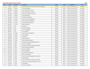
Mold Design Common terms used to describe the tool used toproduce injection molded parts. Injection Molds areconstructed from hardened steel, pre- hardened steel,aluminum, beryllium-copper alloy.In general, steel cost more to construct, but theirlonger lifespan will offset the higher initial cost over ahigher number of parts made before wearing out.Injection Molds / Tool can be manufactured either byCNC machining or by using electrical dischargemachining processes.
Design The consists of two primary components,the injection (A plate) and the ejector (Bplate).
Design Consideration Shrinkage allowance: Depends on shrinkageproperty of material core and cavity size.Cooling circuit: In order to reduce the cycletime, water circulates through holes drilled inboth the core and cavity plates.Ejection gap: The gap between the ejectorplate face and core back plate face shouldhold dimension within the core. It must allowcomponent to be fully removed from the mold.
Design Consideration Mold polishing: The core, cavity, runner andsprue should have good surface finish andshould be polished along material flowdirection.Mold filling: The gate should be placed suchthat the component is filled from the thickersection to thinner section.Draft: Required in both the core and cavity foreasy ejection of the finished component.
Design Steps
2. Parting line
3.
CoreCavity
3. Number of Cavity
Ejector system
Cooling System
Mold Structure: Parting line A dividing line between a cavity plate and a coreplate of a mold. - Make a parting line on a flat or simple-curvedsurface so that flash cannot be generated. - Venting gas or air.
Two plate moldOne parting line
Three plate moldTwo parting lines
Melt Delivery
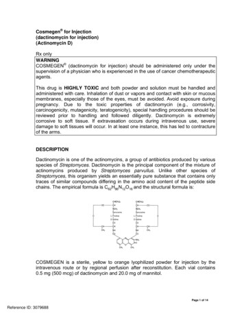
Gate Delivers the flow of molten plastics. Quickly cools and solidifies to avoid backflow aftermolten plastics has filled up in the cavity. Easy cutting from a runner Location is important to balance flow and orientationand to avoid defects.L 0.5-0.75 mmh(thickness) n.tW n A1/230
Runner cross sectionRunner cross section that minimizes liquid resistanceand temperature reduction when molten plastics flowsinto the cavity. Too big Longer cooling time, more material, cost Too small short shot, sink mark, bad quality Too long pressure drop, waste, coolingHot runner, runnerless mold
Runner balancingBalancedNot balanced
DefectsMolding defects are caused by related and complicatedreasons as follows:* Malfunctions of molding machine* Inappropriate molding conditions* Flaws in product and mold design* Improper Selection of molding material
Weldline This is a phenomenon where a thin line is created when different flows ofmolten plastics in a mold cavity meet and remain undissolved. It is aboundary between flows caused by incomplete dissolution of moltenplastics. It often develops around the far edge of the gate.Cause Low temperature of the mold causes incomplete dissolution of the moltenplastics.Solution Increase injection speed and raise the mold temperature. Lower the moltenplastics temperature and increase the injection pressure. Change the gateposition and the flow of molten plastics. Change the gate position to preventdevelopment of weldline.
Flashes Flashes develop at the mold parting line or ejector pin installation point. It is aphenomenon where molten polymer smears out and sticks to the gap.Cause Poor quality of the mold. The molten polymer has too low viscosity. Injection pressure is too high, or clamping force is too weak.Solution Avoiding excessive difference in thickness is most effective. Slow down the injection speed. Apply well-balanced pressure to the mold to get consistent clamping force, orincrease the clamping force. Enhance the surface quality of the parting lines, ejector pins and holes.
Short shot This is the phenomenon where molten plastics does not fill the mold cavitycompletely. and the portion of parts becomes incomplete shape.Cause The shot volume or injection pressure is not sufficient. Injection speed is so slow that the molten plastics becomes solid before itflows to the end of the mold.Solution Apply higher injection pressure. Install air vent or degassing device.Change the shape of the mold or gate position for better flow of theplastics.
Warpage This deformation appears when the part is removed from the mold andpressure is released.Cause Uneven shrinkage due to the mold temperature difference (surfacetemperature difference at cavity and core), and the thickness differencein the part. Injection pressure was too low and insufficient packing.Solution Take a longer cooling time and lower the ejection speed. Adjust theejector pin position or enlarge the draft angle. Examine the partthickness or dimension. Balance cooling lines. Increase packingpressure.
Sink markststs tt-Equal cooling from the surface-Secondary flow-Collapsed surface Sink Mark
Considerations in design of injection molded partsGuideline (3) gate location determines weld linesweld lines* Source: ction design 7.htm
Injection Molding: molds with moving cores and side-action cams- If the geometry of the part has undercuts.
Mold Structure: Undercut, Slide core
Designing injection molds:Typical Features[source: www.idsa-mp.org]
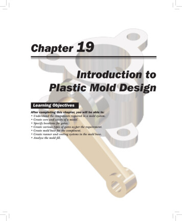
Designing injection molds:Typical Features(a) Shut-off hole:no side action required(b) Latch:no side action required(c) Angled Latch:Side action cam required
Injection Mold Design. Mold Design Common terms used to describe the tool used to produce injection molded parts. Injection Molds are constructed from hardened steel, pre- hardened steel, aluminum, beryllium-copper alloy. In general, steel cost more to construct, but their longer lifespan will offset the higher initial cost over a higher number of parts made before wearing out. Injection Molds .