Transcription
Chapter 5Product andMold DesignProduct DesignMold Design55
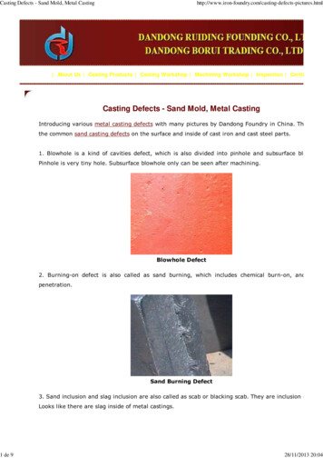
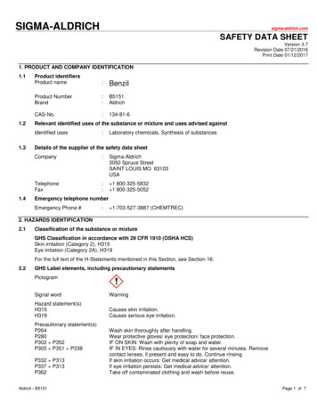
5Product and Mold DesignProduct DesignAlthough component design in thermoplastics is complex, following a few fundamentalprinciples will help you minimize problemsduring molding and in part performance. Ofcourse, the guidelines given here are general.Depending on the particular requirements ofthe part, it may not always be possible tofollow all of our suggestions. But theseguidelines, in furthering your understanding of the behavior of thermoplastics, canhelp you effectively resolve some of themore common design problems.Nominal Wall ThicknessFor parts made from most thermoplastics,nominal wall thickness should not exceed4.0 mm. Walls thicker than 4.0 mm willresult in increased cycle times (due to thelonger time required for cooling), willincrease the likelihood of voids and significantly decrease the physical properties ofthe part. If a design requires wall thicknesses greater than the suggested limit of4.0 mm, structural foam resins should beconsidered, even though additional processing technology would be required.In general, a uniform wall thicknessshould be maintained throughout the part.If variations are necessary, avoid abruptchanges in thickness by the use of transition zones, as shown in Figure 25. Transitionzones will eliminate stress concentrationsthat can significantly reduce the impactstrength of the part. Also, transition zonesreduce the occurrence of sinks, voids, andwarping in the molded parts.56A wall thickness variation of 25% isacceptable in a part made with a thermoplastic having a shrinkage rate of less than0.01 mm/mm. If the shrinkage rate exceeds0.01 mm/mm, then a thickness variationof 15% is permissible.RadiiIt is best not to design parts with sharpcorners. Sharp corners act as notches,which concentrate stress and reduce thepart’s impact strength. A corner radius,as shown in Figure 26, will increase thestrength of the corner and improve moldfilling. The radius should be in the rangeof 25% to 75% of wall thickness; 50% issuggested. Figure 27 shows stress concentration as a function of the ratio of cornerradius to wall thickness, R/T.Draft AngleSo that parts can be easily ejected from themold, walls should be designed with a slightdraft angle, as shown in Figure 28. A draftangle of 1 2 draft per side is the extrememinimum to provide satisfactory results.1 draft per side is considered standardpractice. The smaller draft angles causeproblems in removing completed parts fromthe mold. However, any draft is better thanno draft at all.Parts with a molded-in deep texture, suchas leather-graining, as part of their designrequire additional draft. Generally, an additional 1 of draft should be provided forevery 0.025 mm depth of texture.
Figure 25 – Suggested Designfor Wall Thickness Transition ZoneFigure 27 – Stress Concentrationas a Function of Wall Thickness andCorner RadiusInappropriateAppropriateFigure 26 – Suggested Design forCorner RadiusStress-Concentration FactorP Applied LoadR Fillet RadiusT igure 28 – Exaggerated Draft AngleMinimum TRadius4ReleaseDraftInside Radius TRecommendedNot Recommended57
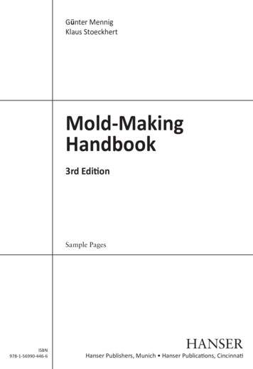
5Product and Mold DesignRibs and GussetsWhen designing ribs and gussets, it isimportant to follow the proportional thickness guidelines shown in Figures 29 and 30.If the rib or gusset is too thick in relationship to the part wall, sinks, voids, warpage,weld lines (all resulting in high amounts ofmolded-in stress), longer cycle times canbe expected.The location of ribs and gussets also canaffect mold design for the part. Keep gatelocation in mind when designing ribs orgussets. For more information on gate location, see page 66. Ribs well-positioned in theline of flow, as well as gussets, can improvepart filling by acting as internal runners.Poorly placed or ill-designed ribs and gussetscan cause poor filling of the mold and canresult in burn marks on the finished part.These problems generally occur in isolatedribs or gussets where entrapment of airbecomes a venting problem.Note: It is further recommended that therib thickness at the intersection of the nominal wall not exceed one-half of the nominalwall in HIGHLY COSMETIC areas. For example, in Figure 29, the dimension of the rib atthe intersection of the nominal wall shouldnot exceed one-half of the nominal wall.Experience shows that violation of thisrule significantly increases the risk of ribread-through (localized gloss gradientdifference).58Figure 29 – Example of Rib Designfdceaa wall thicknessb 0.5 to 0.75ac 3a maximum(if more stiffnessis required, addadditional ribs)bd 2.5a minimume 0.25a (radius corner)f 1 2 per side, minimum(draft angle)Figure 30 – Example of Gusset Designbdecfaa wall thicknessb ac ad 2ae 0.5 – 0.75af 2.5a minimum
Figure 31 – Recommended Design of aBoss Near a Wall (with Ribs and Gussets)RecommendedBossesBosses are used in parts that will be assembled with inserts, self-tapping screws,drive pins, expansion inserts, cut threads,and plug or force-fits. Avoid stand-alonebosses whenever possible. Instead, connectthe boss to a wall or rib, with a connectingrib as shown in Figure 31. If the boss is sofar away from a wall that a connecting rib isimpractical, design the boss with gussetsas shown in Figure 32.Figures 33 and 34 give the recommendeddimensional proportions for designing bossesat or away from a wall. Note that these bossesare cored all the way to the bottom of the boss.Not RecommendedFigure 32 – Recommended Design of aBoss Away From a Wall (with Gussets)RecommendedNot Recommended59
5Product and Mold DesignFigure 33 – Recommended Dimensions for a Boss Near aWall (with Rib and Gussets)a wall thicknessb diameter of core(at top of boss)c 2.5bd 3ae 0.9dmin f 0.3emax f eg 1 2 per side (draft angle)h 0.6a (at base)i 0.25a (radius corner)j 0.6a (at base)hjcbfgdeiaFigure 34 – Recommended Dimensions for a Boss Away Froma Wall (with Gusset)ichga wall thicknessb diameter of core(at top of boss)c 2.5bd 3ae 1 2 per side (draft angle)f 0.25a (radius corner)max g 0.95dmin h 0.3gmax h gi 0.6a (at top of gusset)ebdfa60
ThreadsMolded-in threads can be designed intoparts made of engineering thermoplasticresins. Threads always should haveradiused roots and should not have featheredges – to avoid stress concentrations.Figure 35 shows examples of good designfor molded-in external and internal threads.For additional information on molded-inthreads, see page 105. Threads also formundercuts and should be treated as suchwhen the part is being removed from themold i.e., by provision of unscrewingmechanisms, collapsible cores, etc. Everyeffort should be made to locate externalthreads on the parting line of the moldwhere economics and mold reliability aremost favorable.Figure 35 – Recommended Design forMolded-in ThreadsExternal ThreadsRecommendedNotRecommendedInternal ThreadsRecommendedNotRecommendedUndercutsBecause of the rigidity of most engineeringthermoplastic resins, undercuts in a partare not recommended. However, should adesign require an undercut, make certainthe undercut will be relieved by a cam,core puller, or some other device whenthe mold is opened.61
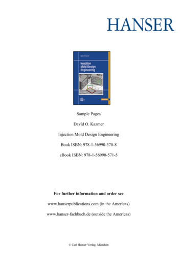
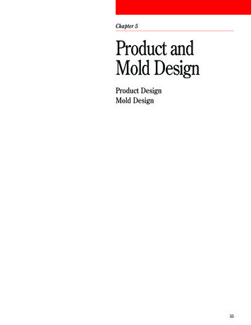
5Product and Mold DesignMold DesignProper design of the injection mold iscrucial to producing a functional plasticcomponent. Mold design has great impacton productivity and part quality, directlyaffecting the profitability of the moldingoperation. This section provides generalguidelines for the design of a good, efficientmold for making thermoplastic parts.Figure 36 – Three Common Sprue PullersSprue BushingsSprue bushings connect the nozzle of theinjection molding machine to the runnersystem of the mold. Ideally, the sprue shouldbe as short as possible to minimize materialusage and cycle time. To ensure clean separation of the sprue and the bushing, thebushing should have a smooth, taperedinternal finish that has been polished in thedirection of draw (draw polished.) Also, theuse of a positive sprue puller is recommended.Figure 36 shows three common spruepuller designs.Runner Geometry ofConventional MoldAnnular RingReverse TaperZ PinFigure 37 – Three Conventional Runner Profiles5 Full Round62TrapezoidalHalf RoundRunner systems convey the molten materialfrom the sprue to the gate. The section ofthe runner should have maximal crosssectional area and minimal perimeter.Runners should have a high volume-tosurface area ratio. Such a section willminimize heat loss, premature solidificationof the molten resin in the runner system,and pressure drop.The ideal cross-sectional profile for arunner is circular. This is known as a fullround runner, as shown in Figure 37. Whilethe full-round runner is the most efficienttype, it also is more expensive to provide,because the runner must be cut into bothhalves of the mold.A less expensive yet adequately efficientsection is the trapezoid. The trapezoidalrunner should be designed with a taper of2 to 5 per side, with the depth of thetrapezoid equal to its base width, as shownin Figure 37. This configuration ensures agood volume-to-surface area ratio.
Half-round runners are not recommendedbecause of their low volume-to-surface arearatio. Figure 37 illustrates the problem. Ifthe inscribed circles are imagined to be theflow channels of the polymer through therunners, the poor perimeter-to-area ratio ofthe half-round runner design is apparent incomparison to the trapezoidal design.Runner Diameter SizeIdeally, the size of the runner diameter willtake many factors into account – partvolume, part flow length, runner length,machine capacity gate size, and cycle time.Generally, runners should have diametersequal to the maximum part thickness, butwithin the 4 mm to 10 mm diameter rangeto avoid early freeze-off or excessive cycletime. The runner should be large enough tominimize pressure loss, yet small enoughto maintain satisfactory cycle time. SmallerFigure 38 – Runner System Layoutsrunner diameters have been successfullyused as a result of computer flow analysiswhere the smaller runner diameter increasesmaterial shear heat, thereby assisting inmaintaining melt temperature and enhancingthe polymer flow.Large runners are not economical becauseof the amount of energy that goes intoforming, and then regrinding the materialthat solidifies within them.Runner LayoutSimilar multicavity part molds should use abalanced “H” runner system, as shown inFigure 38. Balancing the runner systemensures that all mold cavities fill at the samerate and pressure. Of course, not all moldsare multicavity, nor do they all have similarpart geometry. As a service to customers,Dow Plastics offers computer-aided moldfilling analysis to ensure better-balancedfilling of whatever mold your part designrequires. Utilizing mold filling simulationprograms enables you to design molds with: Minimum size runners that deliver meltat the proper temperature, reduce regrind,reduce barrel temperature and pressure,and save energy while minimizing thepossibility of material degradation.Conventional Runner Artificially balanced runner systems thatfill family tool cavities at the same timeand pressure, eliminating overpackingof more easily filled cavities.Improved RunnerBalanced “H” Runner63
5Product and Mold DesignCold Slug WellsRunnerless MoldsAt all runner intersections, the primaryrunner should overrun the secondaryrunner by a minimum distance equal to onediameter, as shown in Figure 39. Thisproduces a feature known as a melt trap orcold slug well. Cold slug wells improve theflow of the polymer by catching the colder,higher-viscosity polymer moving at theforefront of the molten mass and allowingthe following, hot, lower-viscosity polymerto flow more readily into the mold-cavity.The cold slug well thus prevents a mass ofcold material from entering the cavity andadversely affecting the final properties ofthe finished part.Runnerless molds differ from the conventional cold runner mold (Figure 40) byextending the molding machine’s meltchamber and acting as an extension of themachine nozzle. A runnerless system maintains all, or a portion, of the polymer meltat approximately the same temperature andviscosity as the polymer in the plasticatingbarrel. There are two general types of runnerless molds: the insulated system, andthe hot (heated) runner system.Figure 39 – Recommended Design of a Cold Slug WellDMaterial flowDFigure 40 – Conventional Cold Runner Moldsprue bushing64runnersgatesInsulated RunnersThe insulated runner system (Figure 41)allows the molten polymer to flow into therunner, and then cool to form an insulatinglayer of solid plastic along the walls of therunner. The insulating layer reduces thediameter of the runner and helps maintainthe temperature of the molten portion ofthe melt as it awaits the next shot.The insulated runner system should bedesigned so that, while the runner volumedoes not exceed the cavity volume, all of themolten polymer in the runners is injected intothe mold during each shot. This full consumption is necessary to prevent excessbuild-up of the insulating skin and to minimize any drop in melt temperature.The many advantages of insulated runnersystems, compared with conventionalrunner systems, include: Less sensitivity to the requirements forbalanced runners. Reduction in material shear. More consistent volume of polymer per part. Faster molding cycles. Elimination of runner scrap – less regrind. Improved part finish. Decreased tool wear.
However, the insulated runner system alsohas disadvantages. The increased level oftechnology required to manufacture andoperate the mold results in: Generally more complicated mold design. Generally higher mold costs. More difficult start-up procedures untilrunning correctly. Possible thermal degradation of thepolymer melt. More difficult color changes. Higher maintenance costs.Hot RunnersThe more commonly used runne
Mold Design Figure 36 – Three Common Sprue Pullers Figure 37 – Three Conventional Runner Profiles Sprue Bushings Sprue bushings connect the nozzle of the injection molding machine to the runner system of the mold. Ideally, the sprue should be as short as possible to minimize material usage and cycle time. To ensure clean sep- aration of the sprue and the bushing, the bushing should have a .File Size: 210KBPage Count: 19