Transcription
Vol-7 Issue-4 2021IJARIIE-ISSN(O)-2395-4396Injection Moulding Process – An OverviewMayuresh Nitin MadiwaleGraduate Mechanical Engineer, Intern at Amol Enterprises, MIDC Satpur NashikABSTRACTInjection Moulding process is one of the most commonly used among all plastic processing methods due to itsadvantages over other processes. Injection Moulding Process uses high temperature to melt the charge and pressureto inject molten charge in mould cavity. This paper covers a brief overview of Injection Moulding Process alongwith process parameters and their influence; mould design parameters, defects seen in moulded part with theirremedy and latest trends in Injection Moulding ProcessKeywords: - Injection Moulding Process, Thermoplastics, Defects and Remedies, Process Parameters, latesttrends.1. INTRODUCTIONAs the demand of plastic products is increasing in the market, the need of supplying more in less time is alsoincreasing in order to maintain the demand and supply chain. This creates an obligation for manufacturers to reducecycle time and to improve quality. Therefore the conditions are approving for Injection Moulding as its productionrate is high, repeatability is high, low production cost, moderate scrap, vast availability of materials as per need andhas ability to produce required surface finish and engraved surfaces.Manufacturers tend towards “one time setting” of all process parameters and try to achieve their daily productionschedule so as to maintain and improve their competency in the market which is also possible in this process.Waste in production process is also an important factor that leads to loss in efficiency of manufacturing unit andfinancial balance of company. To counter that, the wastage produced in Injection Moulding Process (flash, runners,gates, defective parts) is recycled (Mostly thermoplastic materials).The pressure in IM is relatively less than compression moulding (CM) process as it is only useful for injection stagethereafter full pressure is not required. Thermoplastics are most commonly used material as this group possesseshigher MFI (Melt Flow Index) than that of Thermosets. Thus Thermosets are not suggested to be moulded by thisprocess and another reason being their inability to re-melt. The process starts with granulated raw material which isdried in a drier to remove moisture content and to soften the material before moulding. Then the dried raw materialis poured in the hopper of moulding machine from where it moves to the barrel to be melted. After melting, it is theninjected into the mould from nozzle to sprue bush to runner of the part and then finally in the cavity where itsolidifies and takes the shape of cavity. The barrel is maintained at high temperature to melt the plastic while themould is maintained at lower temperature to initiate and catalyze solidification by means of running cold waterthrough mould or by simple air circulation around the mould. The ejection system arranged in the mould facilitatesthe ejection safely. Thus the process completes with ejection of moulded part.1.1 Requirements of Injection Moulding ProcessInjection Moulding process requires following:1)Raw materialPlastic or Polymer precisely has three main subtypes namely Thermoplastics, Thermosets and Elastomers.Thermoplastics are recyclable upto certain limit. They can be melted by heating and solidified by cooling.Polypropylene (PP), Polyethylene (PE), Polystyrene (PS), Vinyl, Acrylic, ABS, Nylon, and Polycarbonate(PC) are some TP’s used in various applications. On the other hand, Thermosets are not recyclable. Theycan be heated to melt only for first time after which they cannot be used again. If heated again, they willdegrade and will be of no use for moulding thereafter. Phenolic, Polyester, Melamine, Urethane, Epoxy,Alkyd, Diallyl are some TS’s available for various applications. Elastomers group contains polymers with15225www.ijariie.com2238
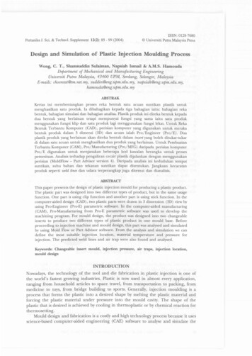
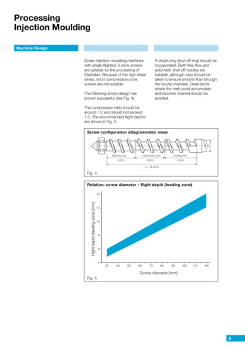
Vol-7 Issue-4 2021IJARIIE-ISSN(O)-2395-4396high elasticity. These are also engineering materials used in various applications which require differentprocesses. Rubber, Butyl, Silicone, Fluorocarbon, Polysulfide, Polysulfide, Neoprene, etc are someElastomers used in day to day application.Thus, Thermoplastics are widely used in Injection Moulding process while Thermosets are moulded byCompression Moulding process.Raw Thermoplastic is available in granules, powders, flakes, tapes, pellets or liquids. These are mainlyavailable in clear or white base colour. To add colour, master batches are added in specific amounts.Master batches can be pigments or dyes. Raw material is dried in a drier to eliminate the moisture contentin plastic and to soften them before melting.Fig -1 Raw Material Granules2) Injection MouldAn accurate and precise mould cavity makes a perfect product. Mould has three main components, Cavity,Core (Punch) and Ejection system. Cavity is the pocket in mould where molten plastic gets filled andsolidifies. Punch covers the cavity and or makes desired alignment with cavity to produce a hole in product.Ejector system helps eject the final product from mould. Cavity is on one side of mould hence it is calledcavity half similarly, punch is on one side of mould, so it is called punch half. Ejector system is usuallyarranged behind cavity side.Mould material plays a vital role in accuracy of product. Components of mould that come in direct contactof plastic such as Punch plate, Cavity plate, Stripper plate are made to withstand heat, pressure and weartear, thus they are made with strong metal alloys such as HDS (Hot Die Steel) or OHNS. Guide pins andejector pins are also made with same material. Other parts such as Top plate, Bottom plate, Punch backplate, Cavity back plate, Ejector plates, and spacers are made with softer material like MS (Mild Steel).Fig -2 Schematic of Injection Mould15225www.ijariie.com2239
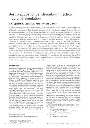
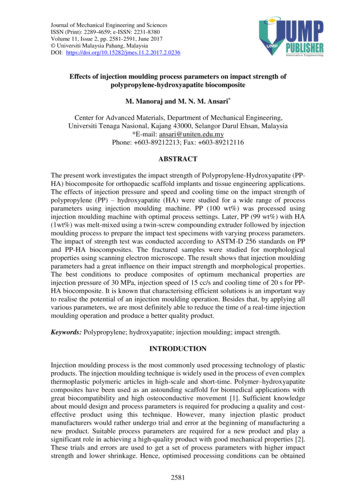
Vol-7 Issue-4 2021IJARIIE-ISSN(O)-2395-43963) Injection Moulding machineInjection moulding machines are available in two types, Vertical Moulding machines, and HorizontalMoulding machines. This is distinguished by the direction of molten plastic through which it enters themould. Vertical machines usually require less floor space and are used for small light weighted productswhile the Horizontal machines require more floor space and are used for heavy and large products. Modernmoulding machines (both vertical and horizontal) usually are fully automatic which theoretically do notrequire any attention from workers.But in practical applications, they are operated as semi automatic machines requiring some attention. E.g.:removing product and runners, adjusting various pressures as per need, lubricating the mould if the productis sticking to it, etc. In Vertical Moulding machines plastic enters the mould through a channel carvedbetween punch and cavity plates. This method is useful only in Vertical Moulding machines; it does notrequire sprue or any auxiliary components. In Horizontal Moulding machines, plastic enters through punchside through a channel or hole drilled. This requires sprue, locating ring and proper channeling to thecavity.Fig -3 Horizontal Injection Moulding Machine2 PROCESS FLOW1) Raw material procurementRaw material in form of granules, sheets, tapes are purchased as per requirement and inspected upon arrival.Incoming inspection is done to assure that the material bags aren’t tampered with or damaged in any way. Alsothe grade and quantity are checked to be sure. Finally it is stored in its appropriate location.2) Pre-Moulding processa)StoragePurchased raw material needs to be stored in a well-ventilated dry place away from direct sunlight andany heat source. Moisture has a bad impact on moulding process thus it should be away from moisture.Thus the bags should not be opened until it is needed.b)Colour mixingRaw material can be procured in two ways, 1) pre-colored with desired colour code or, 2) clear plasticand its separate master batch (Colorant). The choice depends on manufacturer or the client. If masterbatch is to be added to the clear plastic, it is defined by Let-Down Ratio (LDR) which is the ratio ofmaster batch to the base material.E.g.:- If LDR is 3%, master batch is 3 grams per 100 grams of base material.1. Color code system:The colorant is defined by many color matching systems one of which is RAL value .E.g.:RAL 7032 – Pebble grey, RAL 1004 – Golden yellowRAL is a European color matching system which defines colors for paint, coatings and plastics.The RAL color standard is administrated by the RAL Deutsches Institut für Gütesicherung undKennzeichnung. 'RAL' is the abbreviation of 'Reichs-Ausschuß für Lieferbedingungen und15225www.ijariie.com2240
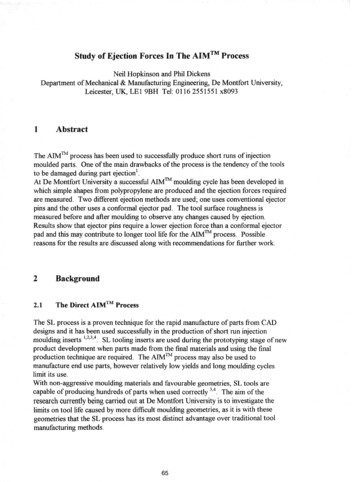
Vol-7 Issue-4 2021IJARIIE-ISSN(O)-2395-4396Gütesicherung'. This name can be translated in English as 'National Commission forDelivery Terms and Quality Assurance'. [1]c)DryingAfter mixing of colorant pigment or granules, the batch is dried in a Blow Drier. This process removesthe moisture content from the plastic. This can also be done in a low temperature furnace.Fig -4 Hopper Drier [4]3) Moulding processa)Shot sizeIn each cycle, a specific amount of plastic is injected into the mould. This amount depends upon theweight of part to be moulded and runner system used in moulding. Extra material in small quantities isalways helpful in ensuring the complete filling of cavity.E.g.:- a part is weighing 50 grams, and runner system is weighing 2 grams, then the shot size is 10 2 12 gramsb) HomogenizationPlastic granules from hopper are fed into the barrel of injection moulding. The screw in the barrel mixesthe plastic thoroughly, this ensures proper color as per requirement and the color is homogenized for theentire batch. After one cycle is completed, the barrel screw turns while moving backwards filling the shotand homogenizing the color simultaneously in this process.c)MeltingHeaters attached at various points on the barrel melts the plastic. Ceramic, MICA band, induction coilheaters are some types of heaters used in injection moulding process. Modern moulding machines have 5point heaters, four on the barrel and one on the nozzle.d) PressurizingThe screw is then fed linearly pressurizing the charge in the barrel. As the screw moves towards thenozzle, the pressure increases because the nozzle area is far less than the barrel cross-sectional area. Thepressure can be controlled with changing the pressure of hydraulic system.e)15225InjectingPressurized charge moves with high velocity as it passes the nozzle and enters the sprue bush. Theinternal aperture of sprue bush is tapered to facilitate the easy removal of runner after the solidification ofpart. This also helps in reducing the jet velocity and increasing pressure similar to a venturi.www.ijariie.com2241
Vol-7 Issue-4 2021f)IJARIIE-ISSN(O)-2395-4396SolidificationAfter complete filling of cavity, the plastic starts to solidify as the mould temperature is significantlylower than the barrel. Also the mould temperature can be controlled by using external aid such as watercooling system.g) EjectionAfter complete solidification, the part is ejected or “De-moulded” from the mould. There can be in-builtejection system which is most widely used in practice or there can be external ejection system such as“Pneumatic Ejection” which requires compressed air supply.Various types of ejection systems include:I.Pin ejectionII.Sleeve ejectionIII.Stripper plate ejectiona. Ejection pin operatedb. Side ejectionIV.Blade ejectionV.Pneumatic ejection (Air ejection)Fig -5 Pneumatic Ejection System Schematic4) Post-Moulding processa)De-flashingFlash/ Burr are difficult to eliminate. Thus the parts are deflashed. Operator removes the flash present onthe edges of the part and also removes the runner attached to the parts. This can be done when next cycleis underway so as to eliminate further processing time.b) ConditioningPost Moulding Conditioning is a process required by some polymer types like Polyamide (Nylon), Acetaland composites like Glass filled Nylon. These polymers absorb water from atmosphere. Water is aplasticizer of these polymers and is necessary for dimensional and structural stability. The time it takes toabsorb moisture from atmosphere and attain equilibrium can be few days, weeks or even months. Thusconditioning is necessary as soon as the part is ejected. Standard procedure suggests the conditioning inwater at 80-85º C for at least an hour.c)15225StorageAfter above steps are carried out, parts are dried again if there is moisture present and stored in a wellventilated, dry room before it can be shipped to the customer.www.ijariie.com2242
Vol-7 Issue-4 2021IJARIIE-ISSN(O)-2395-43963. PROCESS PARAMETERSThere are various process parameters that control the operations. Also Mould design plays a significant role inquality of part moulded. Following are some process parameters:I.Melt temperatureIt is the temperature of the melted plastic. If the temperature is low, the plastic will not evenly melt andmay get stuck in the nozzle or gate area. If too high, it will degrade during the cycle and will evaporate themoisture trapped and will be prone to trapped air bubbles.II.Injection pressureIt is the pressure applied by plunger on the charge. If too high, it will show flow marks in the part and if toolow, the mould cavity will not fill completely.III.Ejection pressureIt is the pressure applied by the ejector rod on the ejection system and on the part ultimately. If too low,part will take longer to leave the cavity. If too high, the part will get deformed and may get scored by thewalls of cavity.IV.Back pressureIt is the pressure applied on the screw on the way to collect new material from hopper. For properhomogenization, this pressure should be controlled properly.V.Screw RPMIt is the speed in revolutions per minute for the screw while it mixes the material for homogenization. If thespeed is low, the material may not mix properly causing colour defects. If too high, it will mix unnecessaryair in the material causing blow holes.VI.Charge massIt is the quantity of material imported in the barrel from hopper. This quantity should be equal to the massof part, runner system and little bit extra to ensure complete filling of cavity. More quantity will affect thepart as it will create flash. Less material will lead to short shot.VII.Hold time / cooling timeIt is the time for which the mould is kept closed after injection is complete. During this time, the partsolidifies inside the cavity. If this time is less, the part will not solidify completely and will get deformed onremoval. If it is more than required, it will increase cycle time.VIII.Fill timeIt is the time for which the injection is carried out. If enough time is not provided, it will cause incompletefilling of cavity. If more, it will cause more material to get inside cavity causing excessive flash.IX.Injection speedIt is the jet velocity of molten plastic. If it is more, it will cause flow pattern on part, which is a problemwhen part is transparent. To avoid this runner design can be made such that it will not let high velocity jetto go inside cavity.X.Ejection speedIt is the speed by which the ejection system will operate. If the speed is more than requirement, it will causedeformation on part. If the speed is less it will increase the overall cycle time of moulding.XI.Clamping forceIt is the force applied by the machine on the mould halves for proper sealing of mould. If less, it may leavegap between the mould plates where material will get filled and flashes would occur. If too high, it willcause damage to the hydraulics of machine and the mould surfaces.15225www.ijariie.com2243
Vol-7 Issue-4 2021IJARIIE-ISSN(O)-2395-43964. MOULD DESIGN PARAMETERSThese are the parameters to be considered while designing the mould. These parameters affect the part quality aswell.I.Number of gatesNumber of gates in a product influences its mechanical properties as well as the cycle time. If more thanone gate is present in the part, there will be weld line created compulsorily. There can be no such partmoulded with a number of gates and no weld line. And when weld line gets created, the structural rigiditywill be compromised specifically when the part is to be used where loads will be applied. To reduce this,the gates should be placed such that the weld line will be on non critical areas of the part. However thecycle time will be reduced dramatically when there is more than one gate.II.Gate sizeIf there is obligation that number of gates cannot be made and the cycle time should be less, then increasingthe gate size can to the trick. More cross sectional area of gate means fast filling of part but much largerportion of part needs to be trimmed of when runner system is being cut. Thus size of gate should beappropriate such that final part does not look shabby on gate location.III.Part’s geometric complexityGeometric complexity of part matters a lot when moulding is being done. A very complex part will takemore time in mould design and manufacturing and hence will cost more. So it should be clear that the partwhen designed for a specific condition should be less complex and easy to mould.IV.Mould materialFor a long run mould material should be capable of handling loads, abrasion and wear and tear. A verysimple mould which will not be used for mass production can be made from mild steel which is cheap aswell as capable for handling load for short duration. On the other hand, most moulds are made with hardermaterials such as P20, OHNS, and HDS which perform excellent in long runs. However, more durablemetal alloys come with more cost. Thus the trick used by majority of mould makers is using harder anddurable alloys in most critical areas i.e. the core inserts, cavity inserts, cavity plate and stripper plate.V.Runner designAn effective runner design leads to effective parts, less consumption of time and less wastage of plastic inrunners. There are several runner system designs the mould makers can choose as per the requirement. Atwo cavity mould will require a simple Y-Balance system assuming each part has one gate. The care shouldbe taken that when more than one part is to be moulded, the effective length of runner from sprue should besame for all parts. This will ensure that same time is required for all parts to be filled with same pressureand velocity of melted plastic.VI.Mould temperatureMould temperature plays a vital role in solidification stage in moulding. The temperature control of mouldis hence necessary and controlled with care. More than required temperature will result in poorsolidification with deformed part at ejection. Too low temperature will solidify the plastic in the runnersystem much prior it reaches the cavity. This will not only be good for part, but will also be bad for themoulding machine as it will create excess pressure in the barrel and on the screw plunger.Mould temperature control depends on type of moulding as well. Injection moulding requires mouldcooling whereas compression moulding requires mould heating. For cooling, air cooled moulds are mostconventional and cheap method but is in affective for large moulds. Water cooled system are used in largemoulds with much improved performance than that of air cooled but requires complex channels carvedinside the moulds which is time consuming and costly.VII.Air vent location and sizeAir vent is a necessary element in the mould. The air trapped in cavity needs to be rejected as the cavitygets filled with molten plastic. It is seen in practice that air gets trapped in an area far away from gatelocation. This is due to the air compressibility. Molten plastic pushes the air towards the far end and cannot15225www.ijariie.com2244
Vol-7 Issue-4 2021IJARIIE-ISSN(O)-2395-4396compress it further causing bubble. Thus air vents are located in such areas if cavity is large. In smallmoldings, the “clearance fit” provided on ejection rods is sufficient to let the air escape. The gap should bein a range of 0.02 to 0.03 mm.VIII.Mould opening/closing speedThis is the speed of mould operation. If the mould closing speed is too high, the collision of plates willaffect the part quality and will also lead to wear and tear of mould itself. If the opening speed is too high,there will be fluctuations in quality and also a high probability of surface scratches on part. Modernmoulding machines are programmed considering this and have the speed variation in three stages. In firststage the speed is slow, followed by a fast second stage and again slow stage at end.5. DEFECTS FOUND IN INJECTION MOULDING PROCESS AND THEIR REMEDIESThere are many defects that can be encountered while moulding. This is because the process has many variables thathave implications on the final part quality. It’s hence important to know the potential defects and the way toeliminate or at least reduce them. Following some defects that can be usually seen and can be avoided by some easytricks and techniques are discussed.Table -1 Defect and their remedies in moulding.Sr.no1Short shotIncrease injection pressure orinjection time. Increase shot sizeby proper calculation2Flow linesIncrease injection temperature ordecrease injection pressure.Change gate location if jet isabruptly gets stopped in cavity3FlashDecrease injection pressure orchange mould design to have lessgaps in cavityDefect15225Remedywww.ijariie.com2245
Vol-7 Issue-4 2021IJARIIE-ISSN(O)-2395-43964Blow holes/ air bubble trappedIncrease injection pressure or addair vents in mould5WarpageInduce slow cooling of part aftersolidification or place weight onparts to reduce the effect.6Surface scratchesApply lubricant spray on cavitysurface to reduce the effect.7DistortionIncrease solidification time ordecrease mould temperature.Reduce ejection speed andejection pressure8Colour inclusionProper purging of plastic afterproduction15225www.ijariie.com2246
Vol-7 Issue-4 2021IJARIIE-ISSN(O)-2395-43969Thermal crackingUsually occurs in initial cycles,increase mould temperature10Blow holesProper air vents required. Slowdown screw rotation speed toreduce air inclusion6. LATEST TRENDS IN INJECTION MOULDINGI.IML (In Mould Labeling)In mould labeling is a part of In-Mould Decoration process which eliminates labeling time and the processafter the moulding is done. The process is carried out by placing the labels to be put on part placed insidethe cavity even before plastic is injected. The process is suitable for mass production. The most commonexample is: - Ice-cream boxes with labels on all four sides.Fig -6 In-Mould Labeling ProcessII.15225Stack MouldsThis is advancement in conventional injection moulds. Conventional mould has only one mould face whilestack moulds have number of mould faces. The mould is divided into three parts. One side is the injectingend which has sprue bush in it. The central core has two faces and both faces have cavities. And third sideis a supporting part which is used to open and close the mould.One other type of stack mould has a rotating central core. This core has four moulding faces which rotatearound its central axis. Due to this rotation, a new face is exposed to the injecting side after a cycle iswww.ijariie.com2247
Vol-7 Issue-4 2021IJARIIE-ISSN(O)-2395-4396completed. This increases the productivity as no time is wasted in removing the part. Then next cycle isunderway, previous part is already facing away from injecting end thus part can be removed withoutstopping the machine for long time.Fig -7 Stack Mould – Mould Closed – Injection Done Fig -8 Stack Mould – Mould Open – Part EjectionFig -9 Rotating Cube Stack MouldIII.Micro MouldingMicro-molding is a highly specialized manufacturing process that produces extremely small, high-precisionthermoplastic parts and components with micron tolerances. The process starts in a tooling departmentwhere a mold is created that has a cavity in the shape of the part desired. Thermoplastic or resin is rapidlyinjected into the cavity, creating the component or part at high speedPart sizes in micron scale that too in high precision and accuracy is possible in Micro Moulding. Partdimensions below 1mm with complex shapes and intricate patterns are maintained by this process. Thisprocess can be single shot or two shot. Two shot micro moulding refers to use of two types of plasticinjected into cavity at same time.IV.Bio Degradable Plastics in Injection moulding [2]Traditional plastics do not decompose easily or rather take years to do so. Biodegradable plastic is avariety that can decompose naturally in the environment. Fermentation of canola oil or sugar can produce apolymer that decomposes under the right temperature and humidity conditions.This makes biodegradable plastic especially well-suited for items and products which will be discardedafter one use.The most common types of biodegradable plastic resins used in plastic injection molding include:1.2.3.4.5.15225Thermoplastic Starch-based Plastics (TPS)Polyhydroxyalkanoates (PHA)Polylactic Acid (PLA)Polybutylene Succinate (PBS)Polycaprolactone (PCL)www.ijariie.com2248
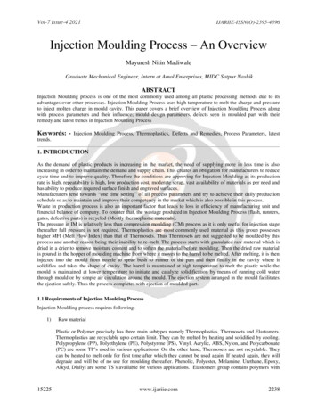
Vol-7 Issue-4 2021IJARIIE-ISSN(O)-2395-4396V.Gas Assisted Moulding [3]The basic concept of the gas-assisted molding process is quite similar to regular injectionmoulding process. In this gas-assisted molding, the plastic material is melted with the help of extruderbarrel and injected into the mold cavities like the regular injection moulding process but only up to70% 80% of the mold volume. Plastic melts in contact with the mold walls begins to solidify and nitrogengas is injected into the mold through strategically designed and placed gas channels, providing pressure thatpushes the plastic material into the mold extremities and finally the molded part is ejected like the regularinjection molding process.VI.Moulding of Structural Foam [4]The Structural Foam Process is a low pressure injection molding process where an inert gas is introducedinto melted polymer for the purpose of reducing density and hence weight of the finished product.Structural foam molded products have cellular cores surrounded by rigid, integral skins. Foaming agent(NI, CO2 or CBA) is introduced into the polymer melt stream, creating a homogenous mixture of polymerand gas. The mixture is short-shot injected through nozzles into the mold in a volume that is less than theamount required to mold a solid part. Injection pressure and expansion of the polymer/gas mixture fills themold. A porous skin is formed when the melt contacts the cold surface of the mold. The expandingpolymer/gas mixture forms the cellular core.Fig -10 Injection of Structural Foam Along With PlasticVII.15225Use of Robotics In Injection Moulding [5]Robots are made to do things which are either too difficult for humans or too labour intensive and timeconsuming. Robots can handle these chores easily and relieve worker’s extra work which in turn improvesproductivity. Highly repetitive actions are tedious to do and also can cause fatigue to workers. This is whyrobotics in injection moulding process can be pain reducer. Machine tending – loading and unloading ofmoulded parts from machine to further processes is the best area for robotic automation. In market there arevarious types of robots available from which a few are discussed below.1. 3-Axis Robots Top Entry RobotsPart picking, In-Mold Decorating (IMD), In-Mold Labeling (IML), Insert Loading, Inspection,Stacking and Palletizing are some of the processes that can be done with this type of robot. Theseare used on Horizontal Plastic Injection Molding Machines (top entry automation applications)and applications requiring higher speed.2. 6-Axis Robots Articulated RobotsFlexible automation on both Horizontal and Vertical Plastic Injection Molding Machines is donewith these robots. Larger working envelope and flexibility in upstream and downstream processesare the advantages of Articulated Robots.3. Collaborative Robots (Cobots)The name itself suggests the function of the robot. Collaborative work of robot with humans is theprimary advantage of this type. Workers can work safely alongside these robots. Alsoprogramming of these robots is way simpler than traditional robots. While traditional robotsrequire an engineer to write the codes for a certain movement to be done, cobots can be easilyprogrammed just by moving the arm in desired location and it will remember the movement. Thisnot only makes working alongside easier but also safer.www.ijariie.com2249
Vol-7 Issue-4 20214.5.6.IJARIIE-ISSN(O)-2395-43964-Axis SCARA RobotsSelective Compliant Assembly Robot Arm - 4-axis robots typically work in Plastic InjectionMolding automation applications for loading and unloading Vertical Injection Molding machines.They have a circular work envelope with flexibility. These can work with other robots such as 3axis or 6 axis robots for work sharing and high precision automation.Side Entry RobotsSide entry robots are single axis robots that perform a specific application. They are capable ofextreme high speed applications such as placing decorations / labels for In-Mold Decorating(IMD) / In-Mold Labeling (IML) and part removal.Servo Sprue PickersServo Sprue Pickers are simple pick-and-place robotic devices used for sprue removal or part andrunner separation in plastic injection molding automation. All three axes i.e. X, Y, and Z axis areservo driven for maximum flexibility and programmability. A simple hand held pendant is enoughto move the robot in desired location with great flexibility and simplicity. Servo sprue pickers arealso capable for pre-staging above the mold. This minimizes cycle time. They are flexibleallowing for deposit on both sides of the injection molding machine - runners out on one side andparts out on the other.1). 3-Axis Robots Top Entry Robots3). Collaborative Robots (Cobots)2). 6-Axis Robots Articulated Robots5). Side Entry Robots6). Servo Sp
the ejection safely. Thus the process completes with ejection of moulded part. 1.1 Requirements of Injection Moulding Process Injection Moulding process requires following:- 1) Raw material Plastic or Polymer precisely has three main subtypes namely Thermoplastics, Thermosets and Elas