Transcription
Journal of Engineering Science and TechnologyVol. 5, No. 1 (2010) 17 - 29 School of Engineering, Taylor’s University CollegeDEVELOPMENT OF SMALL INJECTION MOULDING MACHINEFOR FORMING SMALL PLASTIC ARTICLESFOR SMALL-SCALE INDUSTRIESOYETUNJI, A.Department of Metallurgical and Materials Engineering,The Federal University of Technology, Akure, Ondo State, Nigeria.Email: akinlabioyetunji@yahoo.comAbstractDevelopment of small injection moulding machine for forming small plasticarticles in small-scale industries was studied. This work which entailed design,construction and test small injection moulding machine that was capable offorming small plastic articles by injecting molten resins into a closed, cooledmould, where it solidifies to give the desired products was developed. Themachine was designed and constructed to work as a prototype for producingvery small plastic components. Design concept, operation, and assembly ofcomponents parts were made. Also, working drawings and materials selectionwere made based on calculations of the diameter of injection plunger, numberof teeth required for the plunger rack and spur gear, the angular velocity,number of revolution, torque and power obtained from the electric motorselected and the leverage on the handle of the machine. The machineparts/components were then assembled in line with the designed made,thereafter the constructed machine was tested using high density polyethyleneand master batch. The results obtained from the test were satisfactory.Keywords: Development, Injection, Moulding, Machine, Plastics, Industries.1. IntroductionInjection moulding machine offers many advantages to alternativesmanufacturing methods, including minimal losses from scrap (since scrap piecescan be melted and recycled), and minimal finishing requirements. Injectionmoulding machine differs from metal die casting, in that molten metal’s cansimply be poured, and plastic resins must be injected with force [1]. It is mostcommon used method for mass production of plastic articles [2].17
18OYETUNJI A.Nomenclaturesdd1FglmmhNPrrsTVvDiameter of plunger, mDistance of the handle from the platen, mForce, NAcceleration due to gravity, m/s2Length of injection plunger, mMass of the melt, kgMass of handle, mNumber of revolution, rpmPower, WRadius of plunger, mRadius of motor shaft, mTorque, NmVolume of the melt, m3Injection linear velocity, m/sGreek SymbolsρωDensity of the melt, kg/m3Angular velocity, rad/sThe process involves introducing raw materials in form of granules into oneend of a heated cylinder, heating the materials in the heating chamber, and forcingthe molten metal into a closed mould, where the final solidification of the moltenmetal in form of the configuration of the mould cavity takes [3].The intending injection machine will be made from mild steel and mediumcarbon steel. It can only be used for the production of small components such askey holder, bottle cap, tally, ruler, and clothes peg. The mild steel is used for theconstruction of supporting plates, hopper, mainframe, mould, and platens, handle,and tie bars. This is because; they are not subjected to constant heat. It is easilyweldable, and has good workability but show poor response to heat treatment.An injection moulding machine is a piece of equipment consists of two basicelements, the injection unit and the clamping unit. Injection moulding can be usedwith a variety of plastic resins. The chosen resins for this process arepolyethylene; polypropylene, ABS, and fluorocarbons, because of characteristicsof intricate shapes can easily be produced [4]. The advantages of small injectionmoulding process include good surface finish of the product can be produced, lessscrap and flashes are produced, and the process has relatively low labour costs.The main aim of the research work is to design, construct and testing of smallinjection moulding machine while the specific objectives of the research work areto design and construct a small injection moulding machine, and testing. Thescope of the work is to design and construct a cost effective and environmentallyfriendly small injection moulding machine for the production of small plasticarticles. The research work will involve design concept, operations, designanalysis that will entail design of injection plunger, motor selection, design of thehandle, and the leverage on the handle of the machine. Also, assembly drawingsof the machine, recommended materials and equipment for the construction ofJournal of Engineering Science and TechnologyMARCH 2010, Vol. 5(1)
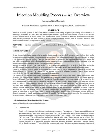
Development of Small Injection Moulding Machine for Forming Small Articles 19design machine will be provided to assist investors that want to venture intoconstruction of this machine.Development of small injection moulding machine for forming small plasticarticles in small-scale industries was borne out of the fact that most injectionmoulding machines were of big size and most small-scale industries in developingcountries could not avoid buying them due to their costs. In solving this problem,there is a need to design small injection moulding machine that is avoidable bysmall scale industries for production of small plastic articles, this is the rationalebehind this work.2. Design Concept and AnalysisThis design concept encompasses the following:a)Maximum volume of the melt needed to fill the mould. This entailsplunger travel (l), diameter of the barrel (d), melt density (ρm) and meltmass (m);b) Design of barrel which entails diameter of the barrel and maximumpiston travel; andc) Design for plunger.While the design analysis entails the following units:a)b)c)The injection unit comprises of the hopper, barrel, heater bands, nozzle,and injection plunger.The clamping unit consists of the mould, platens, and the handle knownas the locking device.The electrical panel comprises of temperature control, contactors,thermocouple, heat resistance wire, and knob (control button).2.1. Design of injection plungerIn the injection plunger design shown in Fig. 1, the volume of the melt (V) theplunger can successfully pushed from the barrel can be determined by knowingthe diameter of the plunger. It goes thus:dlRackFig. 1. Injection Plunger.Journal of Engineering Science and TechnologyMARCH 2010, Vol. 5(1)
20OYETUNJI A.Using Fig. 1, the diameter of the plunger can be determined from Eq. (1)V πr 2l(1)r d/2(2)The expression in Eq. (1) can be expressed in terms of diameter (d),V1 πd2l4(3)Also, volume (V) of the melt in the barrel can be obtained from Eq. (4),V2 mass of the melt, mdensity of the melt, ρ(4)Therefore,V1 V2(5)This implies that,πd2ml 4ρ(6)Making d2 the subject of expression, we haved2 4m(7)πρlTherefore, the plunger diameter can be determined from Eq. (7),d 4m(8)πρlNumber of teeth required on the plunger rackThe number of teeth required is determined from Eq. (9)Number of teeth required on the plunger rack length of travel expected of plungercircular pitch distance(9)Number of teeth required on spur gear (pinion).The number of teeth required on the spur gear is determined from Eq. (10),Number of teeth required on spur gear π diameter of pitch circlecircular pitch distance(10)Motor selectionThe angular velocity (ω) can be determined from Eq. (11),ω v/rJournal of Engineering Science and Technology(11)MARCH 2010, Vol. 5(1)
Development of Small Injection Moulding Machine for Forming Small Articles 21While the number of revolution (N) can be determined from Eq. (12),N 60ω2π(12)In addition, the torque (T) of the motor can be determined from Eq. (13),(13)T FrsLikewise the power (P) can be determined from Eq. (14),P Tω(14)Design of the handleIn the design of the handle, the leverage on the handle (ML) of the machine can bedetermined from Eq. (15),ML mhgd1(15)2.2. Design calculationsIn this work the complete design calculations are made. The design calculationsinclude the calculations of the diameter of injection plunger, number of teethrequired on the plunger rack, number of teeth required on spur gear (pinion),motor selection, and leverage on the handle. These calculations are based on themathematical equations shown in Sec. 2.1. The numerical calculations for theselected concept are outlined in Appendix A.3. MethodsWhen designing the machine, the construction and parts specification, and testingperformance are some of the critical procedures that were followed to achievegood results.3.1. Assembly of machineThe procedures for assembling the machine are as follows:fixing the main frame,position the supporting plates and bolt them together with the tie bars,bolt the barrel to the supporting plate 2,mount the plunger assembly through the supporting plates 1 and 2 to the barrel,positioning of the driven unit to the plunger assembly: the driven unit arespur gear, the reduction gearbox and electric motor,- mount the handle (locking device) through the supporting plate 4 to theplaten, and- install the mould to supporting plate 3 and the platen.-Journal of Engineering Science and TechnologyMARCH 2010, Vol. 5(1)
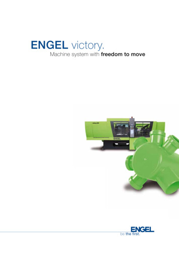
22OYETUNJI A.3.2. Working drawingThe working drawings were produced based on the earlier designed that stateall components of the machine. It gives further internal and external details ofthe entire machine with specifications for the construction. The constructionwas purely based on the designed made. The constructed machine is shown inFigs. 2 to 7.Fig. 2. Plan View of the Constructed Injection Moulding Machine.Fig. 3. Dimensional Plan View of the ConstructedInjection Moulding Machine.Journal of Engineering Science and TechnologyMARCH 2010, Vol. 5(1)
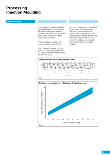
Development of Small Injection Moulding Machine for Forming Small Articles 23hopperFig. 4. Front View of the Constructed Injection Moulding Machine.Fig. 5. Dimensional Front View of the Constructed InjectionMoulding Machine.Journal of Engineering Science and TechnologyMARCH 2010, Vol. 5(1)
24OYETUNJI A.Fig. 6. Side View of the ConstructedInjection Moulding Machine.Fig. 7. Dimensional Side View ofthe Constructed InjectionMoulding Machine.Constructional techniquesThe major techniques employed in construction of the designed machine includemachining operation on lathe machine, drilling operations on drilling machine,flame cutting using oxyacetylene gas welding machines, grinding for goodfinishing, electric welding using arc welding machine. Basically, theseconstructional techniques were broken down into four sub-heading namely;cutting operation, machining operation, welding operation and assembly; andfinishing operation.3.3. Materials selectionMaterials are selected based on designed and metallurgical properties of thematerials such as machinability, formability, weldability that greatly influence theconstruction methods and other joining methods. Other factors considered are costof the materials; and mechanical properties of the materials. MaterialsThe following materials used in the construction of this machine are medium carbonsteel used for injection plunger, barrel and nozzle. Mild steel was used for hopper,supporting plates, tie bars, platen, mould, bolts, and main frame. Other materialsused are thermocouples, limit switches, knobs (control button), bolts, and 4-coreflexible wires, heat resistance wires, and contactors, red and light green paints. Specification of Materials SelectionThe following parts and materials were used to achieve the set objectives. Theyare summarized and presented in Table 1.Journal of Engineering Science and TechnologyMARCH 2010, Vol. 5(1)
Development of Small Injection Moulding Machine for Forming Small Articles 25Table 1. Specifications for Materials Utilized.1Injection plunger2Barrel345HopperSupporting platesTie lMild steelMild steelMild steel678PlatenMouldBoltsMild steelMild steelMild steel9Main frameMild steel10111213HandleElectric it switchesKnobs (controlbutton)NozzleMild steelParts14151617Size(mm)φ22 mm 900 mmQtyProduction1Fabricationφ45 mm 470 mm1Fabrication92 mm 92 mm 115 mm242 mm 22 mm 250 mmPlate 1 to 2φ25 mm 305 mm,Plate 2 to 3φ25 mm 470 mm,Plate 3 to 4φ25 mm 152 mm240 mm 12 mm 240 mm122 mm 25 mm 122 mmM6 thread,M8 thread,M12 thread.1233 mm 380 mm 870 mmφ124 mm 260 mmG-80 type10 ampsJ-type144FabricationBrought outBrought out11186201Brought outFabricationBrought outBrought out1142FabricationBrought outBrought outBrought out222Brought outBrought outBrought out1FabricationJ-typeT85φ28 mmMediumcarbonsteel3.4. EquipmentThe equipment used are as follows: electric motor, other such as mainframe is cutinto sizes using oxyacetylene gas welding, facing operation mould, barrel,injection plunger, and handle were faced using the lathe machine., drillingoperation, milling operation, and tapping operation using drilling machine,milling machine and tapping machine respectively. Components such as thedrilling operation on the lathe machine were performed on the components suchas the mould, barrel, tie bars, and the supporting plates. Milling operation wascarried out on the barrel, and the spur gear teeth. Tapping operation was alsocarried out on the tie bars.All the general finishing operation was carried out on the machine such asgrinding of all rough edges using a hand grinding machine. Cutting saw or framecutting were used for cutting the various metals into sizes and required shapes.Metals such as the supporting plates, platen, tie bars, barrel, injection plunger, andhopper were cut sizes using manual hacksaw.Journal of Engineering Science and TechnologyMARCH 2010, Vol. 5(1)
26OYETUNJI A.3.5. Operation procedureThe operational principles of this machine are as follows: switch on the heater forone hour, and set the electric controllers to the desired temperature, and fill thehopper with materials (high-density polyethylene and master batch). Whenbeginning to inject the molten resins to the mould, make sure the mould is closeand there are two limit switches that determine the stroke of forward andbackward movement of the injection plunger [4]. That is, when the injectionplunger reaches the maximum forward stroke predetermined for the particularmould, a limit switch will be actuated and this will stop the electric motormovement. The same way goes to the backward stroke and this determined theamount of molten resins that goes into the mould. If the mould functions properly,the finished product will fall out of the mould on its own.3.6. TestingIn testing the constructed machine, the materials used for the test are high densitypolyethylene and master batch. The reasons are due to excellent chemicalresistance, very tough at low temperatures; and easy of processing.The steps taken during the test are as follows: materials (resins) are fed intothe hopper, the heater bands heat up the barrel for an hour and when it reaches ahigh temperature (220ºC), and the resins melt into liquid. Thereafter, the mould isheld closed by a handle, which serves as a locking device and a knob is pressedand the injection plunger forces the molten resins under pressure through thesprue into the closed mould cavity, where it cools into a required shape.The volume of the plastic shot is controlled by a limit switch, which shuts offthe electric motor and the plunger when it has reached its stroke. Duringsolidification, a knob is pressed for the injection plunger to move backward untilenough molten resins are being accumulated for the next shot, and the mould isthen opened, and the required product will fall out of the mould on its own.4. Results and DiscussionsIt was found that the major problems in the moulding process are:a) The problem of product or molding that was not fully injected; and thiswas due to the melt temperature either too low or injection has beenstarted before the necessary temperature has been reached. It may also bedue to either the sprue channel is too weak, and or difficulty in the airescaped from mould [5].b) The problem of sinks or blisters on the product or molding was due tothe melt temperature too high, the sprue channel too weak or unsuitablylocated, and the mould is insufficiently cooled.c) Also, the problem of product discolors observed may be due to theoverheated of the melt and the colour fastness of the material.5. ConclusionsThe design, construction and testing of the small injection molding machine hadbeen successfully accomplished. It was observed and concluded that theJournal of Engineering Science and TechnologyMARCH 2010, Vol. 5(1)
Development of Small Injection Moulding Machine for Forming Small Articles 27practicability and efficiency of the machine depends on strict compliance with theoperational procedures of the machine.This work was designed and constructed for the small-scale production ofsmall plastic articles. Hence, it can be recommended for small-scale investors thatare willing to produce small plastic articles such as key holders, clothes pegs, flatrulers, bottle covers/caps and tally.References1.2.3.4.5.6.7.8.Kwong, C.K.; and Smith, G.F. (1998). A computational system for processdesign of injection moulding: Combining blackboard-based expert systemand case-based reasoning approach. International Journal of AdvancedManufacturing Technology, 14(4), 239-246.Niebel, B.W.; Draper, A.B.; and Wysk, R.A. (1989). Modern manufacturingprocess engineering. Mcgraw-Hill Book Company, Singapore, 435-437.Lindberg, R. A. (1990). Processes and materials of manufacture. PrenticeHall of USA, Inc., New Jersey, 247-250.Netstal, C. (1978). Instruction manual for injection moulding machine. NetsalMachine and Foundry Limited, Switzerland, 36-60.Simonson, J.R. (1997). Engineering heat transfer. Mc-Graw-Hill BookCompany, New York, USA, 352.Khurmi, R.S.; and Gupta, J.K. (2003). Machine design. S. Chand andCompany Limited, New Delhi, India, 920-959.Hughes, E. (1995). Electrical technology. Pearson Education Limited.Harlow, England, 699-713.Joseph, E.S.; and Mischke, C.R. (1976). Mechanical engineering design. McGraw-Hill Publishers, Aucland, 162-164.Appendix ADesign Calculationsa) Diameter of injection plungerIn the injection plunger design, the plunger diameter is calculated from Eq. (8),d 4mπρl(8)wheremelt mass, m 2.7 kg (laboratory measurement),melt density of resin, ρ 7900 kg/m3,length of the plunger, l 0.9 m.Substituting these values into Eq. (8) givesJournal of Engineering Science and TechnologyMARCH 2010, Vol. 5(1)
28OYETUNJI A.d 4 2.7 0.022 mπ 7900 0.9This implies that d 22 mmb) Number of teeth required on the plunger rackThe number of teeth required is determined from Eq. (9)Number of teeth required on the plunger rack length of travel expected of plungercircular pitch distance(9)where length of plunger Length of travel expected of plunger 180 mm and circular5 pitch distance 6 mm/toothTherefore, substituting these values into Eq. (9) givesNumber of teeth required on the plunger rack 180 mm 30 Teeth6 mm/toothc) Number of teeth required on spur gear (pinion)The number of teeth required on the spur gear is determined from Eq. (10),Number of teeth required on spur gear π diameter of pitch circlecircular pitch distance(10)whereDiameter of pitch circle 76 mm andCircular pitch distance 6 mm/toothSubstitution of these values into Eq. (10) givesNumber of teeth required on spur gear π 76 mm 40 Teeth6 mm/toothd) Motor selectionIn the selection of the electric motor, the following parameters are required:The angular velocity (ω) is calculated from Eq. (11),ω vr(11)where,Injection linear velocity, v 1.61 m/s [6]Radius of motor shaft, rs 12 mm 0.012 mJournal of Engineering Science and TechnologyMARCH 2010, Vol. 5(1)
Development of Small Injection Moulding Machine for Forming Small Articles 29Substitute these values into Eq. (11) to have1.61 134 rad/sω 0.012Most electric motors operate between 500 rpm and 3000 rpm in accordance withHughes [7]. Hence, the number of revolution (N) is determined using Eq. (12),N 60ω2π(12)where angular velocity ω 134 rad/s and the substitution into Eq. (12) givesN 60 134 1279.5 rpm2πThis implies that,N 1280 rpmIn addition, the torque (T) of the motor is calculated from Eq. (13),T Frs(13)wherethe turning force of G.80 type electric motor shaft, F 0.112 N andthe radius of the motor shaft, rs 0.012 m [7], therefore,T 0.112 x 0.012 0.00134 NmLikewise, the power (P) is determined from Eq. (14)P Tω(14)Recall that the torque, T 0.00134 Nm and angular velocity, ω 134 rad/s,therefore,P 0.00134 x 134 0.17956 kW. This implies that,P 0.18 kWe) Leverage on the handleIn the design of the handle, the leverage on the handle (ML) of the machine iscalculated from Eq. (15) [8]ML mhgd1(15)where,mass of platen, mh 5.39 kg (Laboratory measurement),acceleration due to gravity, g 9.81 m/s2, anddistance in which the handle, d1 moves the platen 180 mm (one fifth of thelength of the plunger) 0.18 m.Substituting these values into Eq. (15) givesML 5.39 x 9.81 x 0.18 9.52 JJournal of Engineering Science and TechnologyMARCH 2010, Vol. 5(1)
An injection moulding machine is a piece of equipment consists of two basic elements, the injection unit and the clamping unit. Injection moulding can be used with a variety of plastic resins. The chosen resins for this process are polyethylene; polyprop