Transcription
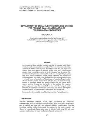
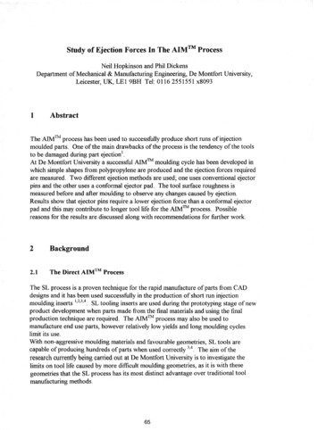
ProcessingInjection MouldingMachine DesignScrew injection moulding machineswith single-flighted, 3-zone screwsare suitable for the processing ofElastollan. Because of the high shearstress, short compression-zonescrews are not suitable.A check ring (shut-off ring) should beincorporated. Both free flow andautomatic shut off nozzles aresuitable, although care should betaken to ensure smooth flow throughthe nozzle channels. Dead spotswhere the melt could accumulateand become charred should beavoided.The following screw design hasproven successful (see Fig. 4):The compression ratio should bearound 1:2 and should not exceed1:3. The recommended flight depthsare shown in Fig. 5.Screw configuration (diagrammatic view)DMetering zoneCompression zone0,25 LFeeding zone0,35 L0,40 LL 18–22 DFig. 4Relation: screw diameter – flight depth (feeding zone)Flight depth (feeding zone) [mm]14121086430405060708090100110120Screw diameter [mm]Fig. 59
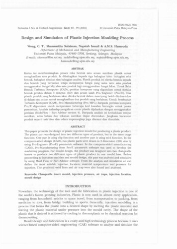
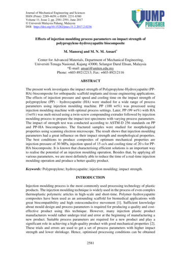
ProcessingInjection MouldingProcessing ParametersTo ensure trouble-free processingand consistently high qualitymoulded parts, precise and constanttemperature control in the injectionmoulding cylinder is necessary.temperature controllers accordingly(see table 4).As Elastollan melts are shearsensitive, excessive screw speedcan cause reduced productproperties.The temperature should increase byroughly 10 to 20 C from the feedingzone to the metering zone. Nozzletemperature should be adjusted tosuit the melt temperature.Fig. 6 shows recommended screwspeeds in relation to screw diameter.Where cycles are interrupted forlonger periods, the material remaining in the cylinder will become overheated. It is therefore necessaryto purge out the cylinder beforeresuming production.Table 3 shows the recommendedbarrel temperatures for variousranges of hardness:It is recommended to measure melttemperature and to adjust machineRecommended barrel temperatures in CShore hardnessHeating zone temperature Nozzle temperature60 A – 80 A85 A – 95 A98 A – 74 ��240Table 3Recommended melt temperatures in CElastollan hardness 60 Shore A to 80 Shore AElastollan hardness 85 Shore A to 95 Shore AElastollan hardness 98 Shore A to 74 Shore D190 to 205205 to 220215 to 235Table 4Relation: max. screw speed – screw diameterScrew speed [rpm]10080max. circumferential 0,2 m/s60402030405060708090Screw diameter [mm]Fig. 610100110120
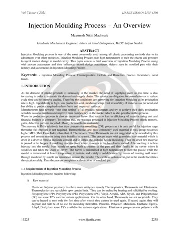
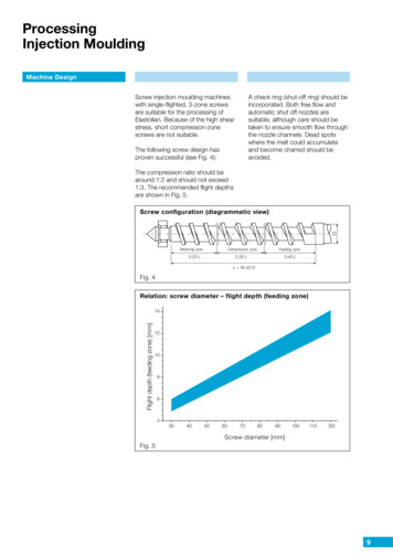
ProcessingInjection MouldingProcessing ParametersCavity pressure pattern during processingpnPressure ppsps Injection pressurepn Holding pressurepst Back pressure100–1000 bar100–1000 bar5– 20 bar(System pressure)Injection speed:as low as possible, dependent ongating, wall thickness and flowpstTime tFig. 7The following machine parametersare especially important for theprocessing of Elastoflan (see Fig. 7):Injection Pressure and HoldingPressureThese factors influence dimensionalstability and ease of demoulding ofthe finished parts. If holding pressureis too low, sink marks may occur.If injection pressure is too high, thendemoulding is more difficult.Back PressureThis effects the homogenization ofthe melt. It should not be set too high,owing to the shear sensitivity of thematerial.Injection SpeedThe correct injection speed isdependent on gating, wall sectionand flow. It should be kept as low aspossible.A typical cycle sequence forElastollan is illustrated in diagrammatic form in Fig. 7.Cycle TimeThe cycle time depends on crystallisation-behaviour and demouldingcharacteristics. Demoulding time isdetermined primarily by mouldtemperature, wall section and hardness of the material.Fig. 8 shows cycle time in relation towall thickness for grades of differentShore hardness.Cycle time in relation to wall thickness20018016060 Shore ATime [s]14012085 Shore A10064 Shore D8060402001Fig. 823456789Wall thickness [mm]11
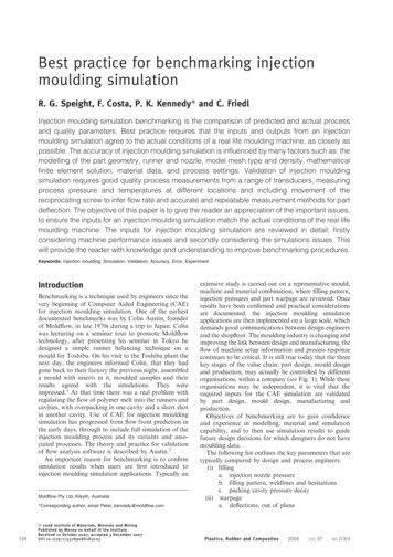
ProcessingInjection MouldingMould DesignMaterials for Mould ConstructionMaterials commonly used for tools,like steel or steel alloys, are suitablefor Elastollan mouldings. Mouldsmade from non-ferrous metals,mainly aluminium, are also workingsuccessfully; these cost-effectivemoulds are often used in footwearmanufacture.SpruesThe maximum sprue diameter shouldnot exceed the maximum wall thickness of the moulding. The diameterof the sprue cone should be adjustedto the nozzle and exceed the nozzlediameter by 0.5 mm. The gate shouldbe located in the area of maximumwall thickness.Runner systemsFig. 9Sprue cones should be as short aspossible and with a minimum angleof 6 . A sprue puller is advisable foreasier demoulding.RunnersThe melt properties of Elastollanrequire large diameter runners toavoid localized shearing and toenable the maximum pressuretransfer to ensure mould filling.Fig. 10For Elastollan, the best flow characteristics are achieved by using acircular runner cross section.GatingGates for the processing ofElastollan should be large, to ensureadequate holding pressure and toavoid sink marks. Critical shear rateis 25 000 s-1.If hot runners are used preferablyexternal heated systems should beselected. Internal heated systemsare not suitable.Multi-cavity tools need a balancedrunner system.Runner cross sectionrectangularhalf-moonunfavourableFig. 1112trapezoidroundtrapezoidbetterroundbest
ProcessingInjection MouldingMould DesignDesigns commonly used includesprue, diaphragm, ring and filmgates. Small parts may also beinjected through pin gates.Submarine gates are not recommended because of the high elasticity and possible shear degradation ofthe material. The softer Elastollangrades are especially prone to problems with this type of gate.VentingAir must be able to escape easilyfrom the mould cavities during injection of the melt, to prevent compressed air causing burn marks. Ventchannels of 0.02 to 0.05 mm in depthare best located at the parting line,at inserts and at pins.Mould SurfaceTo facilitate demoulding, particularlywhen processing the softerElastollan grades, mould surfaceswith a roughness height of approx.25 to 35 µm are recommended.Recommended types of gatefor ElastollanRing gateFig. 12Film gateFig. 13Polished and chrome-plated mouldsurfaces are less suitable, since,especially with the softer grades,they promote sticking of the parts tothe mould surface.DemouldingThe flexibility of Elastollan in thelower Shore hardness range allowsquite large undercuts. Experienceshows that short-term overstretching of less than 5% will not lead topermanent deformation.For trouble-free demoulding, ejectors should be two to three timeslarger than for harder thermoplastics. They should be providedwith venting channels, to preventvacuum during demoulding.Sprue gateFig. 14Mould temperatures may vary from15 to 70 C, depending on theElastollan grade and type ofmoulding.Possible distortion of the mouldedparts can be avoided by varying thetemperature in each half of themould.Mould Temperature ControlA good mould temperature controlsystem is essential for production ofhigh-quality mouldings. Mould temperature has an influence on surfacequality, shrinkage and distortion.13
ProcessingInjection MouldingShrinkageThe shrinkage of Elastollan mouldings is influenced by the followingparameters: For this reason it is difficult to predictshrinkage with any great accuracy.Fig. 15 shows total shrinkage forunreinforced Elastollan grades inrelation to wall thickness and Shorehardness.part designwall thicknessgate designprocessing conditions, in particular melt temperature, injectionpressure, holding pressure,mould temperature.Depending on glass fibre contentglass fibre reinforced Elastollangrades show shrinkage of 0.05 to0.20% in flow direction and of 0.1 to0.5% transversal to flow direction.Total shrinkage is a result of mouldingshrinkage and post-shrinkage whichoccurs not only during annealing, butalso during longer-time storage ofthe parts.Shrinkage in relation to wall thickness2,5Hardness 70 Shore AHardness 95 Shore A2,0Shrinkage [%]Hardness 74 Shore D1,51,00,50012345Fig. 1567891011121314Wall thickness [mm]InsertsInserts can be moulded-in withoutdifficulty. However, for this purpose,Elastollan grades without lubricantare preferred.Metal inserts must be free fromgrease, and should have features formechanical anchorage, such asholes, undercuts, knurled grooves ornotches.14Bonding may be further improved bythe use of primers.It is helpful to temper the inserts.
ProcessingInjection MouldingSpecial Processing MethodsFollowing methods are suitable tocombine other thermoplasticmaterials with Elastollan:Multicomponent InjectionMouldingInjection moulding of Elastollan andcompatible plastic materials onmulticomponent machines createsgood bonding without using additives and mechanical anchorage.Polyolefin based materials areincompatible with Elastollan.layer. Besides the combination ofdifferent thermoplastics it is possibleto use regrind as core componentand virgin grades as outer skin.Gas Injection MouldingIt is in principle similar to sandwichmoulding. Gas is injected as corecomponent for weight reduction.Sandwich Injection MouldingThis is a special method of multicomponent injection moulding wherea core component is combined witha different plastic material as outerTrouble Shooting GuidelinesTrouble shooting guidelinesMeltMouldIntemper- temper- sureShot Clamp- Cooling Venting Mois- Materialsize/ingtimetureconMeltprescontent tamicushion ionBubbles/BlistersBurned spotsDistortion/ShrinkageFlow linesGloss/Matt surfaceFlashingShort shotSink marksSplay marksDemouldingMaterial degradationIncrease to solve problemReduce to solve problemIncrease or reduce to solve problemsTable 515
Injection Moulding Processing Parameters Cavity pressure pattern during processing Fig. 7 p s Injection pressure 100–1000 bar p n Holding pressure 100–1000 bar p st Back pressure 5– 20 bar (System pressure) Injection speed: as low as possible, dependent on gating, wall thickness