Transcription
Study of Ejection Forces In The AIM ProcessNeil Hopkinson and Phil DickensDepartment ofMechanical & Manufacturing Engineering, De Montfort University,Leicester, UK, LEI 9BH Tel: 01162551551 x80931AbstractThe AIM processhas been used to successfully produce short runs of injectionmoulded parts. One of the main drawbacks ofthe process is the tendency of the toolsto be damaged during part ejection1.At De Montfort University a successful AIMTM moulding cycle has been developed inwhich simple shapes from polypropylene are produced and the ejection forces requiredare measured. TWQ different ejection methods are used; one uses conventional ejectorpins andthe other uses a conformal ejector pad. The tool surface roughness ismeasured before and after moulding to observe any changes caused by ejection.Results show that ejector pins require a lower ejection forcethan a conformal ejectorpad and this may contribute to longer tool life forthe AIM process. Possiblereasons for the results are discussed along with recommendations for further work.2BackgroundThe Direct AIM ProcessThe SL process is a proven technique for the rapid manufacture of parts from CADdesigns and it has been used successfully in the production .of short run injectionmoulding inserts 1,2,3,4. SL tooling inserts are used during the prototyping stage of newproduct development when parts.made from the final materials and using the finalproduction technique are required. The AIM process may also be used tomanufacture end use parts, however relatively low yields and long moulding cycleslimit its use.With non-aggressive moulding materials and favourable geometries, SL tools arecapable of producing hundreds of parts· when used correctly 3,4. The aim of theresearch currently being carried out at De MontfortUniversity is to inyestigate thelimits on tool life caused by more difficult moulding geometries, as it is with thesegeometries thatthe SL process has its most distinct advantage over traditional toolmanufacturing methods.65
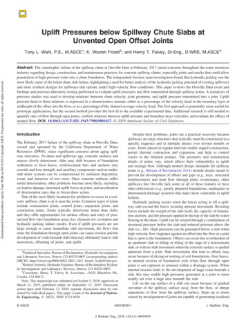
2.2Mould Failure During Part Ejection in the Direct AIM ProcessThe most common sourc.e of failure in SL moulds h s been described as the result ofthe moulding cooling onto featuresintl1ecore causingittobreak during ejection! (seeFigure 1).Moulding contracts as itcoolsCore-------c :: Nji .ormal reaction :::;:,,, dfrictionFigure 1. As the Moulding GoolsitContractsonto the GoreIt can be seen from Figure Ithatasthe part cools it contracts onto the core. It is thiscontraction along withthe sUrface roughness ofthe core Whichleadsto high ejectionforces andtherefore tool failure during ejection. Previousworkinthis area using steeltools has investigatedthe sources of high ejection forces· and their effect onthe qualityofthe moulded part5 , In the case ofdirect AJM'IM tooling, the ejection forces are evenmore important as it is the tool itself which may be damaged.2.3The Study of Ejection Forces in Injection MouldingAs mentioned above, previous work in this area has been carried out with a view tominimising damage to the moulded part. In tpe case of direct AJM'IM tooliIlg theemphasis for the research is.differellt but many of the principles of ejection inconventional·.injection moulding still.a.pply.An equation predictingthe ejection force. based. on various material properties ofthe5mould and moulding has been .qevelopedbyGlanvilland Denton . The eq ation isbased on ejecting a tube fr0 111 a core. The use ofa tube rather than.a closed cylinderlike the one used·in this research is·significant as the ejection force will not need toovercome a partial vacuum between the mould and moulding.The equation is given as:Fe a.(Tm - Te).D.E.A.JlD[(Ol2t - (O.y /4t)]Where:Fe Ejection Forcea coefficient ofthermal expansion of moulding materialTm melting temperature ofmoulding material66
Te ejection temperature of moulding materialD diameter of coreE Youngs Modulus of moulding material at TeA Area of contact between core and moulding in direction of ejectionJl coefficient of friction between moulding material and coret thickness of mouldingy Poisson's ratio for moulding material2.4Different Methods of Part EjectionA number of alternative methods are used for part ejection in the injection mouldingprocess. The simplest and most common method uses ejection pins, however in somecases ejection may be performed using ejector pads, air ejection, sprue pulling orcombinations of these 6. In this research the use of ejector pins and pads areinvestigated. The reason for assessing pad ejection is because the production of anejection pad should be relatively simple using stereolithography.2.4.1 Pin EjectionDuring the design of an injection moulding tool, ejector pins are positioned in a way toallow a clean ejection from the mould without damaging the moulding. The additionof ejector pins to a mould adds complexity, lead time and cost and is generally kept toa minimum.After a part has been moulded and allowed to cool, the mould opens and the ejectorpins are pushed forward to free the part from the mould. Ejector pins are generallyevenly spaced .within a mould to provide an even ejection, however extra pins may berequired where ejection is more difficult such as with deep features in the mould.2.4.2 Pad EjectionPad ejection is very similar to pin ejection except that whole areas ofthe part arepushed by the pad as opposed to scattered points with pins. This provides a more evenejection and is preferred for larger parts which may be damaged by pins.A major drawback ofusing ejector pads is the increased complexity in theirmanufacture. However with the flexibility of stereolithography, a conformal ejectorpad could easily be produced and fixed to ejector pins to provide a more even ejection.3Research MethodologyThe purpose of this research is to investiga.te the process of part ejection in the directAIM process by observing any changes in surface roughness of tools. Also, anyeffects of ejection method were studied by measuring the ejection forces required.67
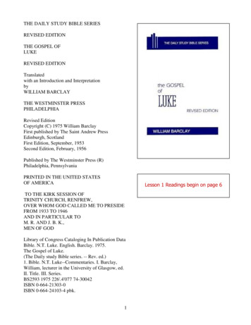
3.1Tool DesignThe basic tool design was based. on investigating the principle of failure during ejectionas shown in Figure 1. Two factors· which required attention were the possibility ofusing both pin and pad ejection for the same tool and also to ensure that the corewould be able to with stand the ejection forces without breaking.3.1.1 Allowing Both Pin and Pad EjectionTo allow both pin and pad ejection the closed cylinder shape (shown in Figure 1) had acollar added to its base as shown in Figure 2. This design also allows the use ofthinner cores with the same ejection set up.--CollarSprue]l ------------ JFigure 2. Cross Section of Test Mouldings Produced3.1.2 Ensuring that the Core Would Not Break During EjectionIn order to produce a number of mouldings and perform a number of tests it wasimportant to ensure that the core would not break off during ejection. Using theequation described earlier to predict the ejection forces along with estimates ofmaterial properties and temperatures an acceptable core design was found.Appendix 1 shows the estimates of material properties and tool temperatures based onprevious work. These data are fed into Glanvill and Denton's equation and tooldimensions which may result in failure are calculated. Based on these calculations itwas decided to use a core with an overall length of 40mm and diameter of 20mm witha 2mm wall thickness.3.2EquipmentThe equipment required for this research is described briefly below.3.2.1 Injection Moulding machineA Battenfeld 600 CDC 60 ton injection moulding machine was used. This wascontrolled by a UNILOG4000 text based programming language which allows easychanging ofthe many parameters involved in the injection moulding process.3.2.2 Injection Moulding toolsThe tools used were made from solid SL5170 resin using the ACES build style on anSLA250 machine (see Figure 3). The mould design included a single round corefeature to ensure an even shrinkage of the moulding onto the core. The core was38mm long with a base diameter of 16mmand a 1.50 taper. A 40mm diameter flange68
at the base provided an area for ejection and all wall thicknesses were 2mm. Thedesign ofthe tool with no large flat areas ensured that part distortion after an earlyejection would not occur.The parts were built so that the direction of ejection would be parallel to the z buildaxis, this maximised the effects of stair stepping on part ejection but is commonplace inthe production ofSL injection moulding tools. To maintain repeatability betweendifferent moulds each insert was thorougWy cleaned between part building and postcuring. No other form of finishing was used. Equally spaced steel ejector pins wereused to eject the mouldings.Figure 3: ACES lM Injection Moulding Inserts Used3.2.3 Measurement of Surface Roughness of CoresThe surface roughness ofthe cores were measured using a Taylor Hobson Talysurfmachine. The Talysurf drags a stylus over a surface, plots its profile and calculates theroughness average (Ra).3.2.4 Measurement of Ejection ForcesThe ejection forces were measured using 3 load cells each ofwhich consisted of a 4arm wheatstone bridge. The load cells were mounted behind the ejector pins tomeasure forces in the direction of ejection (see Figure 4).Load cellDirection ofEjection ForceEjector Front PlateEjector Back PlateFigure 4. The Load Cells Housed Behind the Ejector Pins69
3.2.5 Measurement of Tool TemperaturesThe tool temperature was measured fromthe centre ofthe core using a K Typethermocouple. TheSL core had a 2mm hole from the base to the centre of the core.After part building,·· the thennocouplewasinsertedinto the hole.and thertSL5170 resinwas injectediTltothehole ensurin that no air was trapped. The core was then postcuredinthenortnalway for·l . hours.3.2.6.DataAcquisitionwith Visual ProgrammingThe signals from the ·load cells and the thermocouple were fed into an analogue signalconditioning unit. .This t,whiFhwascontrolled byHPVee visuaLprogrammingsottware,wasus d oY l?lifytheanalogue. signals before sendingtbem to the hostcomputer; jtals /providedie citation for load cells.TheBPVeepro raIUllri glanguageiallowed a great deal of fleXibility in terms of cquisition.and1l1tl Plllation.g i'idata.For.example, the effects offriction recordedwhen actuating· thei ej ctorpinsi}cOllldbe simply·measuredi·andautomatically subtractedfrom the ejectionreadingeacl1timeamoulding was ejected.3.3ExperimeJl.tal.C()llditioDS3.3.1. Measurement ofS1.lrfaceiRoughnessMeasurements of surface roughness were made at 12 fixed positions to ensurerepeatability between results. Ata distance of 7mm from the base of the core, 6equally spaced points were measuredfor surface roughness. Similar readings weretaken at a distance of 7mm from the top of the core.3.3.2 Injection Moulding Machine ParametersMelt injection was performed at the lowest speed possible on the machine which was5% of full speed. The peak injection pressure measured by the load cells through theejector pins was 2000 psi (14MPa) and no packing pressure was applied as no surfaceripples due to cooling in the mould could be seen.3.3.3 Cycle Times and Tool CoolingCooling times were varied as these would greatly affect the melt temperature atejection (Te) which, according to Glanvill and Denton's equation will affect theejection force (Fe). The longest cooling time used was 480 seconds and the shortesttime was 20 seconds.For each moulding, the core temperature was allowed to cool to 55 degrees C beforethe next shot was performed. This ensured that the tool was below its glass transition(Tg) at the start of each cycle.3.3.4 Data Acquisition ParametersMeasurement ofthe ejection forces required a quick sampling rate of 1000Hz to catchthe peak values. The raw signal included some noise and was smoothed tocompensate. The rate of change oftool temperature was much slower and a samplingrate of only 1Hz was required for this.70
4Results4.1Surface RoughnessSutface roughness measurements were taken to assist with estimating the ejectionforces and to observe any changes caused by running the tools.surfaceroughnessscale inmicrons Ra6j53radialposition oncore surface4--7MM FROM BASE OF CORE-.-7MM FROM TOP OF COREIFigure 5. Polar Plot of Surface Roughness of Core Used with Ejector Pins Before use.-----surfaceroughnessscale inmicrons Raradialposition oncore surface1065341--7MM FROM BASE OF CORE -.-7MM FROM TOP OF CORE IFigure 6. Polar Plot of Surface Roughness of Core Used with Ejector Pad Before use.71
4.1.1 Roughness Average ValuesFigure 5 shows a polar plot ofthe surface roughness ofthe tool which was used withejector pins before any mouldings were taken. Figure 6 shows a sil11ilar plot for thetool \Vhich was due to be used wit?analul11inium ejector ring. Both plots show thatthe surface roughness measured was betwe n 3 and 7 l11icrons Ra except for positionfrom the top of each core. Bubbles could be seen on these parts at thisnumber 4, 7position which·explains the higher Ra values.mmsurfaceroughnessscale inmicrons RaI1065radialposition oncore surface34- t-7MM FROM BASE OF CORE--7MM FROM TOP OF COREIFigure 7. Polar Plot ofSurface Roughness of Core Used with Ejector Pins After 50Shotsradial------position oncore surfacesurfaceroughnessscale inmicrons Ra62/53104I--7MM FROM BASE OF CORE--7MM FROM TOP OF COREIFigure 8. Polar Plot of Surface Roughness of Core Used with Ejector Pad After 50Shots72
Figures 7 and 8 show the polar plots for the cores shown in Figures 5 and 6 after 50shots had been taken. There appears to be no real change in surface roughness after 50mouldings for 11 of the 12 points measured. The roughest point on the original plotsappears to have been smoothed after 50 mouldings.4.1.2 Surface Profile TracesFigure 9 shows a typical surface profile from the core used with pin ejection before anymouldings had been made. As expected, a regular "shark tooth" profile can be seen.Figure 10 shows the surface profile from the same point on the same core after 50shots. There appears to be no change in the profile of the surface roughness and this isconsistent with the results which showed no change in Ra values.I\Ii:i. II. iIII'II.!IFigure 9. Surface Roughness Profile ofCore Before Being Usedwith Pin EjectionIIFigure 10. Surface Roughness Profile ofCore After 50 Shots had been producedwith Pin Ejection4.2Pin EjectionFigure 11 shows the ejection forces recorded against cooling time for mouldingsejected with ejector pins; The graph shows that as cooling time is increased (andtherefore melt temperature at ejection is decreased) ejection force is increased. This isconsistent with Glanvilland Denton's equation as are the magnitudes offorces whichare up to 300 Newtons.600,-- ------------------------,----,500ens::} 400Ql6 300& s::o t 200 100 jjJ' 0 0100150200250300350400450Cooling Time (seconds)Figure 11. Graph ofEjection Force against Cooling Time Using Ejector Pins73500
For each. specified cooling period there. appears to be a significant range of eJectionforces measured. The reason forthismaybethatthe temperature ofthe mouldingvaries whel1the ejectiontiIn.eis keptthesatne. ·The temperature measured inside thecore appears to be consistent with the· ejectiontimes,.howe er the core Illaterial·is aninsulator sothe temperature at the centre ofthe core may olllygive aroughindicationofth lll?uldingtemperature.Itis hn.portan.t to remember that it is the temperature ofthelllouldiI).grather than. the temperature ofthe centre ofthe core which will dictatethe ejectionforce.4.3AluDliniuIIlRing.Eje4;tionFigure 12 showstlleejectionforces pl ttedagainst cooling time for parts ejected usingan alutIli!1ium ejector Pad. U11like the graph for ejector pins there is no il1g times. Also, the forces measured arehigher (up to 500 Newtons) than. thosefoul1d with ejector pins.The reason for higher ejection forces was thought to be due to greater cooling at thebase of the core due to the aluminium ejector pad acting as.a heat sink. In order to testthis theory, an ejector padmade fromNylon with amuchlower thermal conductivitywas used and tested.600 500.1/1c:01z400(I)e3000u.c:0:g L- I 200(I)iIi'1000 --.,. ------,--- -.,------,----.- - . , - - - - , - - - - - - , - - , . . - o50100150200250300350400450500Cooling Time (seconds)Figure 12. Graph ofEjection Force against Cooling Time Using Aluminium EjectorPad4.4Nylon Ring EjectionFigure 13 shows the ejection forces plotted against cooling time forparts ejected usinga Nylon ejector pad. The graph is almost identical to that for the aluminium eje tor.pad. This suggests that the higher ejectionforces are caused by the method of ejectIOnrather than any local cooling caused by heat sinks in the tool.74
600500.(i)c:4001z-. 300I0u. I , . . . . I *.c:0 200LiT1000 ------1o50100200150250300350400450500C(.)Oling Time (seconds)Figure 13. Graph 6fEjection Force against Cooling Time Using NylonEjector Pad5Con.clusions and DiscussionSurface Roughness of CoresThe measureme.nts taken fter 50shotssho",edthat for most .parts ofthe tool surfacethere was no change inisurface roughness. This suggests thatthere is no plasticdeformation ofthe tool surface and measurem.entsofroughnesstaken from themouldings are . similar to thos .ofthe.t()ol. Thisindicates.that. during eJection, eitherthe tool or the moulding or both are able to deform elastically before returning to theiroriginal state.i 5.2Ejection ForcesAll of the ejection forces measured were within the range which might be· expectedpins.increas dasexpectedwithlonger.coolingitimeshowever this.wasnotthe.casewith ad ejector . ()nepossible rea onforthehig erejectionforcesusing pads is thatair is· not able to .filltheivoid.between the mould and moulding at. the. earlystages ofejection. Ifthisisthe.rea.son r.lligherejection . forces,then.itslJggeststhat the use··ofpins allows ·airto.fill the gap betw enmould.andmoul iing thusireducingthe ejectionforce. It is possible that usi g pins causesthe moulding to bend while still on the corethus allowing air betvveen the mouldandm.()l.l1ding. . Illdeed,giyen thatthe jectionforce versus coolingtimegraphprofil using pins is similar to that predicted by75
Glanvill and Denton's equation using an open cylinder, this theory would seemreasonable.Another possible reason for higher ejection forces using pads is that the ejection profileusing pads is steeper than that using pins. This suggests that the moulding is pushedoff more quickly using pads and therefore the acceleration applied is greater whichrequires a higher force.5.3Further WorkTheresults presented above. showed two areas which are difficult to explain andtherefore require closet attention. Firstly the higher ejection forces using ejector padsmay be investigated by performing tests.withdifferent ejector methods. For exampleejection with 2 ejector pins could be compared to that with 6 ejector pins. If a moreeven ejection results in a higher force then it could significantly ease mould design withfewer pins.Secon?ly, the variation in ejection forces after the same cooling time may be explainedby some variation in the actual temperature atejection. Further tests should beperformed· with the temperature of the moulding being recorded rather than thetemperature of the centre ofthe core.6References1.Jacobs, P.F. Recent Advances in Rapid Tooling from Stereolithography.Proceeding ofthe 2nd NationaEConference on Rapid Prototyping and ToolingResearch. Buckinghamshire College 1996. ISBN: 085298 98222.Decelles, P. and Bamt, M.Direct AIMTM Prototype Tooling, Procedural Guide3D Systems, Valencia, CA,USAPIN 70275/11-12-963.Rahmati, S. and Dickens, P.M. Stereolithography Injection Moulding Tooling6th European Conference on Rapid Prototyping and ManufacturingNottingham UK July 1997 ISBN 0 9519759 7 84.Jayanthi,S. Hokut:B. McConnell,R.· Speer, R.I. and Fussell, P.S.Stereolithographic Injection Moulds for Direct Tooling8th SFF Proceedings Austin Texas September 97 ISSN 1053-21535.Glanvill, A and Denton, E Injection Mould Design Fundamentals.Industrial Press, NY 19656.Pye,R.G.W. Injection Mould Design 2 EditionThe Plastics and Rubber Institute 1978 ISBN 07114 3906 0nd76
Appendix 1Glanvill and Denton's equation for ejection force is:a.(Tm -FeTe).D.E.A. D[(D/2t - (D.y /4t)]The equation can be re-written as:Fe D 2 a(Tm-Te).E.1t.L. D 2.(1/2t - y/4t)Where L is the core length.The D 2 cancels out on top and bottom so the theoretical ejection force Fe isindependent of core diameter.Using the following figures, ejection forces for different core diameters can beevaluated.a 6.8 x 10⁻⁵ K-l (linear)Tm 1600CE 245 MPaA 1t.D.L 0.5t 2rnmy 0.35Length of Tool (L) 40rnmUsing an ejection temperature (Te) of 1000C gives an ejection force of289NUsing an ejection temperature (Te) of600C gives an ejectionforce of 482NThese predicted forces (remembering that a trapped vacuum has not been accountedfor) can be compared with the predicted tool strength which is governed by crosssectional area and tool temperature.Max Temp of Tool 800CTensile Strength of Tool at 800C12MPaTherefor for failure at 800C:Fe 12.1t(D/2iFor a 10rnm diameter tool 12.1t(D/2)2 942NFor a 20rnm diameter tooI12.1t(D/2i 3768NThese calculations show that both a 10rnm and 20rnm diameter core should be strongenough to resist tensile failure assuming no vacuum exists between the mould andmoulding.77
78
3.2.1 Injection Moulding machine A Battenfeld 600 CDC 60 toninjection moulding machine was used. This was controlled by a UNILOG4000 text based programming language which allows easy changing ofthe many parameters involved in the injection moulding process