Transcription
INJECTION MOULDING: WARPAGE REDUCTION BY REDUCINGRESIDUAL STRESSVOO CHUANG SHINA project report submitted in partial fulfilment of therequirements for the award of the degree ofMasters of Engineering (Mechanical)Faculty of Engineering and ScienceUniversiti Tunku Abdul RahmanJanuary 2015
iiDECLARATIONI hereby declare that this project report is based on my original work except forcitations and quotations which have been duly acknowledged. I also declare that ithas not been previously and concurrently submitted for any other degree or award atUTAR or other institutions.Signature :Name:Voo Chuang ShinID No.:13UEM03819Date:
iiiAPPROVAL FOR SUBMISSIONI certify that this project report entitled “INJECTION MOULDING: WARPAGEREDUCTION BY REDUCING RESIDUAL STRESS” was prepared by VOOCHUANG SHINhas met the required standard for submission in partial fulfilment ofthe requirements for the award of Masters of Engineering (Mechanical) at UniversitiTunku Abdul Rahman.Approved by,Signature :Supervisor : Dr. Chen Kah PinDate:
ivThe copyright of this report belongs to the author under the terms of thecopyright Act 1987 as qualified by Intellectual Property Policy of University TunkuAbdul Rahman. Due acknowledgement shall always be made of the use of anymaterial contained in, or derived from, this report. 2015, Voo Chuang Shin. All right reserved.
vSpecially dedicated tomy mother who nagged me all the way to take my masters.Also to my Bumblebee and Jodyfish.
viACKNOWLEDGEMENTSI would like to thank everyone who had contributed to the successful completion ofthis project. I would like to express my gratitude to my research supervisor, Dr.Chen Ka Pin for his invaluable advice, guidance and his enormous patiencethroughout the development of the research. Also for him being more awesome thanother supervisors for having so much free time for me In addition, I would also like to express my gratitude to the following peoplein the industry for providing the necessary drawings, moulding data as well as givingadvice on moldflow simulation techniques: Jack Dubourg – Lifesize, Engineering Manager Steve Parks– Lifesize, Sales & Marketing Manager KT Beh– CPI, Engineering Manager KH Lim– CPI, Deputy Engineering Manager EL CHuah– CPI, Project EngineerSpecial recognition to my Supervisor, Pn Puziah for covering my ass when Ihad to steal time for my studies.
viiINJECTION MOULDING: WARPAGE REDUCTION BY REDUCINGRESIDUAL STRESSABSTRACTInjection moulding is one of the most popular methods of processing polymers. It is aversatile process capable of producing high volumes with good dimensionaltolerance while maintaining cost effectiveness. Over a third of all plastic products aremade using injection moulding while over half of the world’s polymer processingequipment is used for injection moulding process. Warping, a major defect ininjection moulding is the deformation of a moulded component caused by nonuniform changes in internal stress, differential shrinkage and/or orientation effects.One of the main factors affecting warping is residual stress, the stresses that remainswithin the moulded part, when there are no external loads applied to the system. Inthe case study, the part of concern: a faceplate experiences major warping and itaffects the assembled end product. Changes are proposed to reduce the residual stressin the part post moulding, which will reduce part warpage as a result. The proposedchanges to be studied are gate size, gate quantity, gate location and mould surfacetemperature. In order to predict and study the effects of these proposed changes tothe warping, CAE software Moldflow Plastic Insight (MPI) is used to carry out thesimulation. MPI requires no introduction in the field of mould design andoptimisation, as it is one of the most widely used CAE solutions in the industry. MPIis a 3D solid-based simulation tool that allows plastic part designers and mouldmakers to successfully predict design manufacturability and quality duringpreliminary stages of product development. From the simulation studies, it isconcluded that gate size have a minor effect on reducing residual stress and warpingwhile gate quantity and location have a significant impact in reducing residual stressand warpage. Increasing mould surface temperature also reduces residual stress byreducing both flow-induced and thermal-induced residual stress.
viiiTABLE OF CONTENTSDECLARATIONiiAPPROVAL FOR SUBMISSIONiiiACKNOWLEDGEMENTSviABSTRACTviiTABLE OF CONTENTSviiiLIST OF TABLESxiiLIST OF rping21.31.2.1Injection (Filling) Rate31.2.2Cooling Rate31.2.3Cavity Pressure41.2.4Melting Temperature41.2.5Gate Design4Residual Stress51.3.1Flow-induced residual stress51.3.2Thermal-induced residual stress61.4Rationale71.5Computational Fluid Dynamics91.5.191.6MeshingMoldflow Plastics Insight 10
ix2341.6.1Beam Mesh101.6.2Midplane Mesh111.6.3Dual-Domain Mesh121.6.4Tetrahedral Mesh121.6.5Computational Time131.7Case Study141.8Aims and Objectives151.9Problem Statement151.10Proposed Solution16LITERATURE REVIEW172.1Process Parameters Optimisation: Taguchi Method172.2Effects Of Temperature and Pressure on Warpage192.3Material Strength versus Warpage Resistance Relationship 222.4Gate and Runner Designs232.5CAE and Other Numerical Methods24METHODOLOGY263.1Research Scope263.2Resources Required263.3Simulation Methodology273.3.1CAD – Geometry Preparation273.3.2CAE – Moldflow Simulation283.4Simulation Variables293.5Desired Result Output29RESULTS AND DISCUSSIONS304.1Simulation Pre-Study304.1.1Mesh Type304.1.2Mesh Size324.2Gate Study344.2.1Gate Size354.2.2Gate Quantity39
x4.354.2.3Gate Position, Gate 1414.2.4Gate Position, Gate 2424.2.5Gate Position, Gate 345Mould Temperature464.3.1Temperature Change – Original Gate Design474.3.2Temperature Change – Optimised Gate Design48CONCLUSION AND 51REFERENCES52APPENDICES55
xiLIST OF Simulation results for varying mesh type withmesh size 1mm, Gate radius 1mm31Simulation results for varying gate size with meshsize 5mm, mesh type Dual Domain35Simulation results for varying gate size with meshsize 5mm, mesh type Tetrahedral36Simulation results for varying gate quantity withmesh size 5mm, mesh type Tetrahedral39Simulation results for varying gate position withmesh size 5mm, mesh type Tetrahedral, gatequantity 142Simulation results for varying gate position withmesh size 5mm, mesh type Tetrahedral, gatequantity 243Simulation results for varying gate position withmesh size 5mm, mesh type Tetrahedral, gatequantity 345Simulation results for varying mould surfacetemperature with original gating, radius 1 mm,position datum, gate quantity 147Simulation results for varying mould surfacetemperature with mesh size 5mm, mesh type Tetrahedral, gate quantity 248Recommended final design and parameters50
xiiLIST OF FIGURESFIGURETITLEPAGE1.1Injection Moulding Machine21.2Warpage of injection moulded part due todifferences in mould wall temperature3Flow-induced residual stresses developed due to ahighly oriented solidified polymer molecules.Darker areas represent the frozen layers and (1)high cooling, high shear, and anisotropic orientedzone (2) Low cooling, low shear, and isotropiczone5Thermal-induced residual stress caused by unevenmaterial shrinkage, creating uneven stressdistribution of compressive and tensile stresses inthe finish part61.31.41.5Beam element (1D) mesh111.6Midplane element (2.5D) mesh111.7Dual-domain (2.5D) mesh121.8Tetrahedral (3D) mesh131.9Total Solution time for three different mesh types131.10Faceplate of the decoder141.11Poor fitting of the faceplate and the decoder141.12Process flow chart to determine probable solutionsto the warpage problem16A direct sprue gate extruded from the sketchlocated on the guide line273.1
xiii3.2Diagram showing warping deflection in the z-axis.Positive deflections are in red and yellow shadeswhile negative deflections are in blue shades. Thediagram is not to scale, exaggerated for clarity2Error! Bookmark not defined.4.1Mid Plane mesh (b) as opposed to Dual Domain(a). The features in Mid Plane are distorted andgaps appear in the mesh31Graph of simulation time (mins) versus the Meshsize(mm).Simulationtimedecreasesexponentially with decreasing mesh size33Graph of simulation accuracy (Actual-simulation)in percent % versus the mesh size. Total deflectionaccuracy (green line) decreases with increasingmesh size344.4Direct sprue gate354.5Graph showing stress sensitivity increases withmesh density and levels out. Accuracy is increaseswith increasing mesh density till a saturation point37Simulated results showing the pressure distributionat end of fill. First result shows pressure for gatesize r 1mm and last result shows pressure forr 5mm. The red spot (where pressure is highest)noted to spread out with increased gate size38Simulated results showing the pressure distributionat end of fill. First result shows pressure for gatequantity,n 1 and last result shows pressure for n 3.The pressure reduces significantly and is dark bluefor n 2 and light blue for n 340Gate position in terms of percentage (%) fromdatum41Graph of total deflection (mm) versus gate positionfrom datum (%). Total deflection is lowest forposition 20-8044Pressure at end of fill for different gating locations.Pressure is lowest for position 80-20444.24.34.64.74.84.94.10
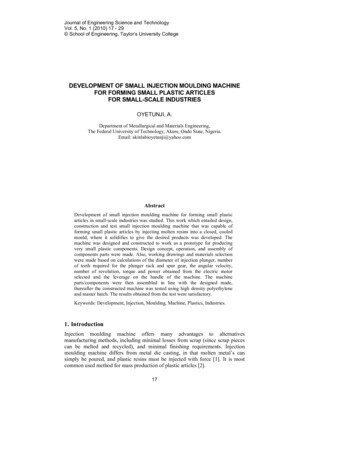
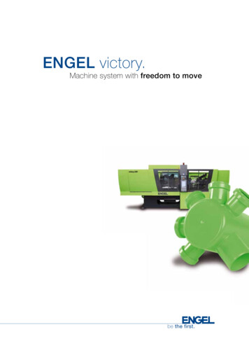
1CHAPTER 11 INTRODUCTION1.1BackgroundInjection moulding is one of the most popular methods of processing polymersespecially those with complex geometries. Injection Moulding is especially suitablefor processing in high volumes with good dimensional tolerance while maintainingcost effectiveness. It is extremely versatile, able to fabricate a wide range of productsfrom small plastic gears to large television panels. Over a third of all plastic productsare made using injection moulding while over half of the world’s polymer processingequipment is used for injection moulding process (Beaumont, Nagel and Sherman,2002).The injection moulding process is basically divided in 5 stages. They areplasticization, injection, packing, cooling and ejection. Though the stages may seemfairly simple, they are actually very complex in nature affected by a myriad ofparameters. Hence, part manufacturing defects are common. These defects includewarping, weld lines, burn marks, short moulds and streak marks to name a few.Among these, warpage is the most prominent and serious defect as it affects bothcosmetic features as well as functional features. Figure 1.1 shows a full injectionmoulding machine with the mould in place.
2Figure 1.1: Injection Moulding Machine (Source: PMolds Industrial)1.2WarpingWarping or warpage is the deformation of a moulded component caused by nonuniform changes in internal stress, differential shrinkage and/or orientation effects(Goodship, 2004). The most influential parameters affecting warpage includes:mould and melt temperatures, design of the injection moulded part, cooling system,length to thickness ratio, packing pressure and time, gate type, dimension and itslocation (Goodship, 2004). Semi-crystalline plastics are generally more prone towarping than amorphous plastics as they are anisotropic in flow, shrinking contrarilyin the direction of flow and transverse to flow (Peacock and Calhoun, 2012). Theroot cause of warping can be divided into five main groups: Incorrect processing parameters Mould design issue Injection moulding machine problems Part design issue Poor plastic material selectionWith the assumption that the injection moulding machine, part design andmaterial selection are all without problems and constant, that leaves variables ofprocessing parameters and mould design open to changes.
31.2.1Injection (Filling) RateLow injection rates will cause a lower viscosity in the material, requiring higherinjection pressures to push the material into the mould cavity. This will leave higherresidual stress in the part. High injection rates on the other hand results in highshearing of the material at the gate, adding to internal stress. High filling rates alsocauses material orientation, resulting in immediate as well as post-mouldingshrinkage.1.2.2Cooling RateMoulded parts that are ejected hot due to short cooling is more likely to warp than apart ejected cold. The part warps due to the asymmetry in heat distributionthroughout the ejected part itself, due to differences in geometry or mould walltemperature differences (Bociga et. al, 2010) (Fig. 1.2). The side that is still hot, orcools more slowly will continue to shrink upon cooling whereas the side that hasalready cooled will stop shrinking or shrink less. Semi-crystalline polymers formlarger crystals on the slower cooling side (Paulson, 2015).Large crystals will shrinkmore than smaller crystal, which makes semi-crystalline materials more prone towarping.Figure 1.2: Warpage of injection moulded part due to differences in mould walltemperature.
41.2.3Cavity PressureCavity pressure during injection is always highest closest to the gate. Hence, plasticshrinks less in the gate area than plastic at the end farthest from the gate. Higherpacking pressure and holding pressures reduces the mean free volume of the plastic,contributing to lower shrinkage during cooling cycles. With lower overall shrinkage,the warpage of the plastic part can be reduced with increasing cavity pressure.However, higher pressures may contribute to the residual stress in the part which willaffect part warpage.1.2.4Melting TemperatureChanges within the melt temperature affect all primary variables by change of plasticviscosity. It is always better to follow the recommended melting temperature asprovided by the material’s Material Safety Data Sheet (MSDS). Low meltingtemperatures will generally result in higher residual stress in the part post moulding(Paulson, 2015)1.2.5Gate DesignGate location is critical as flow front from the gate should be as uniform as possible.If any portion of the flow front starts to move backwards to the gate instead of awayfrom the gate; weld lines and voids from entrapped air will occur, resulting in extrainternal stresses in the part (Tang et. al, 2005). If the gate size is too small, it can alsogenerate large shear stresses within the material as it flows through the gate. Thehigh shear stress will also contribute to warpage of the part.
51.3Residual StressResidual stresses are the stresses that remain within the moulded part, when there areno external loads applied to the system. Internal stresses affects a part similarly tostresses applied externally and is the main cause of uneven shrinkage andwarping.There are two types of residual stress in injection moulding process, flowinduced residual stress and thermal-induced residual stress (Östergren, 2013).1.3.1Flow-induced residual stressFlow-induced residual stress occurs when the moulded part solidifies before thelong-chain polymer molecules are able to achieve its unstressed and random-coilstate of equilibrium. There will be a highly oriented anisotropic frozen layer (skin)on the surface part due to a combination of high cooling rates and high shear stressesof the polymer melt adjacent to the mould wall (Fig 1.3) (Östergren, 2013). The skinforms at the edge of the mould wall because of the metal’s good conductivity, whichin turn acts as an insulator to the polymer melt in the core. This enables the corepolymer to relax to a higher degree and better reach equilibrium, leading to isotropic,low molecular orientation zoneFigure 1.3: Flow-induced residual stresses developed due to a highly orientedsolidified polymer molecules. Darker areas represent the frozen layers and (1) highcooling, high shear, and anisotropic oriented zone (2) Low cooling, low shear, andisotropic zone (Source: Östergren, 2013)
61.3.2Thermal-induced residual stressThermal-induced residual stress can occur for several reasons. One of the mainfactors to it is uneven material shrinkage. At the beginning of the cooling cycle, theexternal surface close to the mould wall, is the first to cool and shrink forming anouter skin. This leaves the core partially molten and still free to contract. However,the rigid external skin acts as a constraint, limiting contraction when the inner corecools (Fig 1.4). The resulting constrained cooling is thermal-induced residual stressin the part. Compressive stresses develop at the skin as a result while tensile stressesdevelops in the core, which generally enhances the material’s fatigue properties(Östergren, 2013).Figure 1.4: Thermal-induced residual stress caused by uneven material shrinkage,creating uneven stress distribution of compressive and tensile stresses in the finishpart(Source: Östergren, 2013)
71.4RationaleThere have been numerous efforts made in the last few years since the beginning ofthe century to improve warpage control techniques. However, many researchersfocused on using numerical methods such as Moldflow simulator combined withstatistical methods such as Taguchi orthogonal array and Analysis of Variance(ANOVA) methods. These researchers believe that their studies demonstrate howprocess parameters can be effectively optimised using Taguchi methods, validated bymoldflow software. However, this in turn only widens the gap between academicresearch and industrial practical applications, due to the impracticability ofimplementing the studies.Manufacturers generally do not take these studies seriously as there are manyother factors that affect quality. These factors usually ignored in the studies includes:machine tonnage, machine brand, clamping force, surface aspects, cycle time, mouldconstruction and many others. Note that even when there are two identical machineshaving the same specifications, bought from the same manufacturer; these twomachines would in practice produce goods of slightly different quality in respect toeach other. Moreover, factories do not generally have the necessary experiencedemployees, time and resources to carry out such detailed studies especially withcomplex products like cameras, where they may be over 3 dozen separate plasticcomponents used. It would be extremely time consuming to carry out these studies36 times, affecting the time to release the goods to market quickly.Hence, many plastic manufacturers design the moulds and parts based onexperience and general plastic design guidelines. This saves time and money and ifthe designer or tool maker is very experienced, little modifications only need to bemade to the moulds in order to achieve good moulded parts. However, this can goawry sometimes and massive tooling modifications are required.
8The challenge involved in situations like this is to correct the part defectwithout increasing cycle time. Sanchez, R., Aisa, J., Martinez, A. and Marcado, D.(2012) like many others found that cooling time is the most significant parameteraffecting part warpage. Manufacturers honestly detest and despise recommendationsto increase cooling time to improve part quality as it bites into their productivity andultimately profit margin. Such suggestions are always met with scorn unless it issuggested by the customer itself and the customer is willing to pay the extra costs.Hence, the focus here is to generate cost effective counter measures to solvethe warping problem. As process parameters have already been pushed to the limitsin this case, there are only two options: 1. Use a cooling jig or 2. Toolingmodifications. Cooling jigs though do not generally affect cycle time, it does makethe process more labour intensive. In long terms, this might still cost the plasticmoulder higher manufacturing costs. Hence, we have to look into toolingmodifications. For tooling modifications one feasible option is to change andoptimize the gating type. Senkerik, et al. (2012) attributes built up internal stresswithin the moulded part as a major contributor to the warping phenomenon and it canbe remedied by changing the gating.As tooling costs are expensive and may take several modification trials anderrors before obtaining a solution, it is recommended to use simulation software tofirst test out the suggested solutions. Injection moulding simulation software likeMouldflow Plastic Insight (MPI) offers an effective solution, allowing the designerto test different gate designs before committing the designs to the tool shop. This inturn saves the moulder money from reduced physical trails.
91.5Computational Fluid DynamicsComputational fluid dynamics (CFD) is a branch of fluid mechanics that utilisesnumerical methods as well as algorithms to analyse and solve problems regardingfluid flow. CFD provides a qualitative method to predict fluid flows by usingmathematical modelling (e.g. partial differential equations), numerical methods (e.g.discretisation and solution techniques) and other software tools (e.g. solver, pre/postprocessing utilities) (Kuzmin, 2012). CFD is based on Navier-Stokes equation thatdescribes correlation of pressure, velocity, temperature and density. CAE is the useof computer software to carry out CFD engineering analysis. The software to be usedfor injection moulding CFD analysis is Moldflow Plastic Insight from Autodesk.1.5.1Moldflow Plastics Insight Moldflow Plastic Insight (MPI) requires no introduction in the field of mould designand optimisation, as it is one of the most widely used CAE solutions in the industry.MPI is a 3D solid-based simulation tool that allows plastic part designers and mouldmakers to successfully predict design manufacturability and quality duringpreliminary stages of product development. Moldflow enables the users to avoidpotential problems downstream which may lead to production delays and costlyoverruns such as numerous tooling modifications. MPI represents a complete suite ofadvanced simulation tools for plastic process to predict and eliminate potentialmanufacturing problems and to optimise mould design, part design, materialselection as well as processing parameters.
101.6MeshingThe first step in CFD is to define a geometry, made up of a series of finite volumes.These finite volumes or elements are referred to as a “mesh” and is normally formedby 2-D or 3-D elements. The main purpose of mesh is to allow for Navier-Stokesdiscretisation of the partial differential equation, enabling numerical computations(Jaworski, 2004).After meshing, boundary conditions and the transport properties must bespecified including any appropriate turbulence models before a solution can beinitialised. Some issues and limitations with CAE software are the need todifferentiate and select mesh type, the need to attain convergence results prior toanalysis and the need to correctly use appropriate transport and physical propertieswithin the simulation software.There are generally three basic element types inmeshing. They are: Beam elements (1D): 2-noded elements used for tasks such asmodelling cooling channels and cold runners Triangle elements (2.5D): 3-noded elements used for Dual Domain andMidplane mesh types modelling. Tetrahedral elements (3D): 4-noded elements used for 3D mesh typemodelling.1.6.1Beam MeshBeam elements are basic, one-dimensional (1D) line that connects two nodes with anassigned, cross-sectional area shape (Fig. 1.5) (Jaworski, 2004). They are usuallyutilised for representation of melt delivery systems such as runners and cooling lines.Beam elements may also be used to represent beam-like part geometry such asscrewboss. In beam elements, the flow is assumed symmetrical about the central axis. Thebeam should have a length two to three times its diameter.
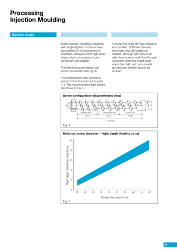
11Figure 1.5: Beam element (1D) mesh (Source: Moldflow Tutorial)1.6.2Midplane MeshA midplane or shell mesh is a representation of a three-dimensional part using twodimensional plane surface within the centre of the part (Fig 1.6). The place surface isassigned a thickness property, hence the 2.5D terminology. Midplane mesh worksbest for thin-walled injection moulding applications as to reduce computational timein CAE simulation. In this mesh, it is assumed that the flow length of a cross sectionis greater than its apparent all thickness, referred to as Hele-Shaw approximation(Jaworski, 2004). Significant errors may occur when midplane mesh is wrongly usedfor parts not considered thin-walled. As a rule, the minimum average length shouldbe four times greater than the local thickness. A more conservative rule exists,where the minimum width to local thickness ratio should not be less than 10:1. Themore a model digresses from these guiding principles, the greater the potential oferror in analyses. This is an issue with beam shapes such as air vents and grills.Figure 1.6: Midplane element (2.5D) mesh (Source: Moldflow Tutorial)
121.6.3Dual-Domain MeshA Dual-Domain mesh is a three-dimensional part represented by using skin mesh ortwo-dimensional boundary of the outside surface of a part, translated from ComputerAided Design (CAD) models such as STL or IGES format (Fig 1.7) (Jaworski, 2004).The dual-domain mesh is similar to the shell mesh except the boundary shell isaligned and matched for the outer surfaces. The part thickness is defined by thedistance between the mesh surfaces. Mesh density plays an important role indetermination of geometries with varying thickness such as hinges or drafted ribs.The same limitations in thickness ratio that applies to midplane mesh also applies todual-domain, it is more suitable for thin-wall parts.Figure 1.7: Dual-domain (2.5D) mesh (Source: Moldflow Tutorial)1.6.4Tetrahedral MeshA tetrahedral mesh, is a four-node element gives a 3D representation of the part byfilling the volume of the model (Fig 1.8). 3D mesh works well with any geometry orpart that does not adhere to the thickness-limitation ratios as in midplane mesh. Astetrahedral utilises Navier-Stokes equations rather than Hale-Shaw approximations,the 3D analyses requires extra computational time to complete. This makes 3D meshsuitable for thick models with complicated geometries.
13Figure 1.8: Tetrahedral (3D) mesh (Source: Moldflow Tutorial)1.6.5Computational TimeComputational solution time is an important consideration when choosing a meshtype for analysis. As multiple iterations or trials are required for successfulsimulation study in a work environment, carrying out simulations that require longertimes will pile up and cost significant amount of time. The total solution timeconsists of model preparation (mesh repair, set constraints, boundary conditions)time and analysis calculation time. These are reliant on the model’s element type andsum, complexity and user selected analysis option. In general, Moldflowrecommends dual-domain mesh as it provides the best combination of modelpreparation time and the time for analysis for most simulations (Fig. 1.9).Figure 1.9: Total Solution time for three different mesh types. (Source: MoldflowTutorial)
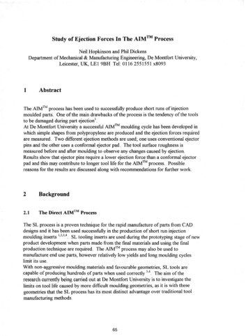
141.7Case StudyThe part in focus for this study is a faceplate (Fig 1.10), part of a decoder fromLifesize Communications. The faceplate forms the front cover and is made ofInfrared transmitting polymer, PC Lexan 940A from Sabic. The main problem withthe faceplate is part warping, causing poor fit with the main housing (Fig 1.11)creating a cosmetic defect. The part has a total part length of 330mm and width of35mm, which makes it highly susceptible to warpage due to its high length to widthratio. The part warpage is up to 2mm total and in order to obtain a good fit, it must bebrought down to less than 1mm.Figure 1.10: Faceplate of the decoder. (Source: Lifesize)Figure 1.11: Poor fitting of the faceplate and the decoder.Due to market pressure that requires immediate release of the product tocapture the market, production continued with help of cooling jigs and increasedinjection moulding cooling time which contributed to higher overall costs. Defectrates were also high, adding to the production scrap costs.
151.8Aims and ObjectivesThe aim of this project is to: Reduce the warping of the faceplate to a value less than 1.0 mm withoutchanges to the part design and without increasing production cycle time.The objectives of this study are to: To reduce warping in the faceplate to a value less than 1.0mm. To offer a cost effective solution that does not increase cycle time. To reduce residual internal stresses through optimised gate design. To determine the optimum gating layout, type and size for this case study. To simulate and verify design effectiveness. To optimise simulation mesh and constraints to obtain low and efficientcomputational time without sacrificing accuracy. 1.9To study the effects of mould surface temperature on the residual stressProblem StatementQuestion to statement on hand:How can the warping from an injection moulded plastic part be minimised oreliminated by reducing the residual stresses?Problems:i.Warpage occurs post moulding and the final moulded part has poor fit withthe main housing unitii.Process parameters have been pushed to the limits and warping still occursiii.Cycle time must not be increased to make manufacturing cost effectiveiv.Part geometry of the face plate is long and moderately thinv.Mould have been tooled, with both core and cavities finishedvi.Too late to change part geometry and design post tooling
161.10Proposed SolutionThe proposed probable solution to the problem statement is in the flow chart asbelow (Fig 1.12)How to solvewarping?Reduce residualStressHow?Change ostNOToo ositionFigure 1.12: Process flow chart to determine probable solutions to the warpageproblem.
17CHAPTER 22 LITERATURE REVIEW2.1Process Parameters Optimisation: Tag
made using injection moulding while over half of the world’s polymer processing equipment is used for injection moulding process. Warping, a major defect in injection moulding is the deformation of a moulded component caused by non-uniform changes in internal s