Transcription
P O LY M E RInjection Molding GuideS O L U T I O N S
Injection Molding Guidebarrel of the molding machine, they achieve a viscous fluid statecharacteristic of a polymer much like low-density polyethylene.Contents:Introduction. 2Materials. 2Equipment Requirements. 3Mold and Part Design. 4The Molding Operation. 6Startup Procedure. 9Troubleshooting Guide. 10Theoretically, TPUs can be injection-molded; but from a practicalstandpoint, many, particularly the softer grades ( 70A), are not viablefor practical, commercial use. Many of the softer types are nearlyamorphous; consequently, molding would require long setup times.They could be very tacky and stick to the metalmold surfaces.Melt viscosities suitable for molding will generally be lower than fortypical extrusion processing. Temperatures and shear forces inthe molding machine barrel will be higher than for extrusion. Someof the harder grades will have melt temperatures approaching450 F/232 C. In general, 450 F/232 C is the onset of TPU thermaldegradation. All LifeSciences TPU grades can be injection-moldedbelow this temperature; individual Technical Data Sheets should beconsulted and the recommendations followed. Products should beselected from the LifeSciences molding product sheets. If a specificset of end-use physical properties is found on on the LifeSciencesTPU Extrusion list, it is very likely that the grade can be successfullyinjection-molded.Molding conditions can be recommended by Lubrizol technicalrepresentatives.IntroductionLifeScience LifeSciences is a business within The LubrizolCorporation that provides innovative polymer solutions forhealthcare products. Among the chemical technologies employedby LifeSciences are thermoplastic polyurethane elastomers (TPUs).LifeSciences TPUs are grouped into several families of productswith varying chemical and physical characteristics. They can bereadily converted to durable, tough, impact-resistant articles suchmedical device housings, tubing connectors, etc., on conventionalthermoplastic injection-molding equipment.The harder thermoplastic polyurethane TPU compounds arespecifically designed for fast, easy injection-molding of large andsmall parts. By the nature of their chemical structure, the softerTPU compounds, in the Shore hardness range of 70A to 90A, willtake longer to set-up (longer cycle times). Many of the grades areformulated with small amounts of additives to facilitate mold releaseand prevent blocking of molded parts. All TPU materials produce avery low-viscosity melt compared to other thermoplastics such aspolyethylene. Polyethylene PE is a crystalline polymer that still hasa relatively high melt viscosity when the crystalline structure “melts”it. This is due to the high molecular weight (length of polymer chain)of PE. PE can have molecular weights above 1,000,000. In contrast,when a harder (e.g.g. 50D) TPU melts, it goes to a low melt viscosityrapidly. This is due to the relatively low molecular weight of TPU.TPU will typically have molecular weights in the 100,000 to 200,000range. Once melted, increasing the melt temperature generally doesnot reduce the melt viscosity significantly.This brochure is intended to provide general guidelines forequipment, procedures and molding machine conditions that willhelp the customer obtain the best possible performance from the theLubrizol LifeSciences of TPU molding grades. Additional informationcan be obtained by consulting individual product Technical DataSheets or by contacting your Lubrizol technical service or salesrepresentative.MaterialsLifeSciences TPUs are available in both aromatic and aliphatic types.The choice of polyol raw material during manufacture leads to thefamilies of polyester, polyether and polycarbonate grades. Separateliterature is available describing detailed properties of the variousmolding grades. All of these TPU types have common characteristicsas far as basic molding processing behavior and practices. Thisguide covers those general characteristics.TPUs are generally not considered to be crystalline polymers thatwould be represented by a product like low-density polyethylene(PE). Some of the harder TPU grades ( 90 Shore A) could beconsidered semicrystalline. Softer grades 62A–85A can be nearlyamorphous — they have no definite melting point, but softengradually on heating. Upon heating and shear mixing within theTPU melt viscosity easily fills the most complex mold cavities underlow injection pressure. The low viscosity melt permits the materialto flow through small gates and into thin wall sections under lowinjection pressure. Low-viscosity melt combined with low injectionpressure minimizes the possibility of producing highly stressed parts.2
P O LY M E RS O L U T I O N SEquipment RequirementsClamp CapacityType of MachineA new machine having a minimum clamp force of 300 kg/cm2to 400 kg/cm2 (2 to 3 tons/square inch) of projected part area,including runners, is recommended. The area of runners in a threeplate mold should be included.Although all types of machines have been successfully used, areciprocating-screw machine is preferred for molding LifeSciencesTPU compounds. A reciprocating-screw machine is capable ofproducing the most uniform melt, is the most easily controlled, and iscapable of the fastest cycles.Screw and TipThe screw and tip designs that are designated "general purpose" arebest. The compression ratio of most of the general-purpose screwsfalls between 2:1 and 3:1; this range is the most desirable for meltingand homogenizing TPU compounds.Machine SizeBarrel capacityTo obtain the widest processing latitude and optimum physicalproperties, an appropriate match of shot size, (i.e., volume of cavities,runners and sprue) to barrel capacity is very desirable.A shot weight of 60% to 75% of barrel capacity is recommended.The general-purpose tip usually has a 60 included angle and afree-flow mechanism of either ball check or sliding ring type. It isrecommended that an antibackflow valve, in good working order, beused when TPU compounds are molded. The low viscosity of theirmelts makes satisfactory packing-out of the mold cavity very difficultunless an antibackflow device is used.This minimizes melt residence time in the barrel, enabling processingat higher stock temperatures with optimum melt flow while avoidingdegradation.NozzlesSince the optimum match of barrel capacity is not always practicaldue to clamp requirements or machine availability, shot sizes aslow as 30% to 35% may be used with the understanding that theprocessing latitude of the material may be significantly reduced.Lower stock temperatures mean higher melt viscosity and moreresistance to flow. Greater injection pressures will be needed to fillthe part, and molded-in stresses may result. It is likely that thesemolded-in stresses could adversely affect impact, dimensionalstability and other properties of the finished part.A straight, open nozzle with a full internal taper tip is recommended.A positive-shut-off, antidrool nozzle can be helpful but is not anecessity. If the particular machine or mold design requires a longnozzle or a nozzle extension, it should be well insulated with heaterbands so that there are no cold spots. The harder TPU compounds,because of their sharp melting point, can crystallize (set up) if a coldspot exists. The next shot will result in cold slugs of material carriedinto the cavity along with the hot melt. The longer the cycle requiredby the particular part, the more troublesome this can become;therefore, the nozzle must be well insulated with heater bands. Thebands must extend as close to the tip as possible.When calculating optimum barrel capacity, always consider thespecific gravity of the TPU compounds versus the specific gravity ofthe material for which the machine was rated. Most machines arenormally rated for kilograms (ounces), a unit of weight of generalpurpose polystyrene.MoldsAny type of mold that incorporates good thermoplastic designprinciples is satisfactory for TPU compounds. Two-plate, three-plateand hot-runner molds have all been used successfully for a varietyof large and small parts. For hot-runner molds, as with nozzles, itis important that heaters provide full coverage of the runner systemso that cold spots do not exist; the TPU can be maintained in itsfluid melt state. The mold must also be adequately cored for coolingbecause TPU normally requires a relatively cool mold [(10 C to 44 C)(50 F to 110 F)] to produce optimum cycle. The nozzle tips withinthe hot-runner mold must be well-insulated from the cold side ofthe mold. Poor insulation and the quick setup characteristics ofTPU compounds (primarily the harder grades) can lead to pluggednozzles. A sheet of transite separating the hot and cold sections ofthe mold is recommended.Example: Given that the specific gravities of TPU compoundsand general purpose polystyrene are 1.20 and 1.05, respectively,a 1.7 kg (60 oz.) barrel rated in general-purpose polystyrene willdeliver 1.9 kg (67 oz.)* of TPU.*1.7 kg x 1.2 1.9 kg (67 oz.)1.05A targeted TPU shot weight, including sprue, runners and parts,would then be 1.4 kg (50 oz.) on this machine.(1.9 kg x 75% capacity 1.4 kg or 50 oz.)3
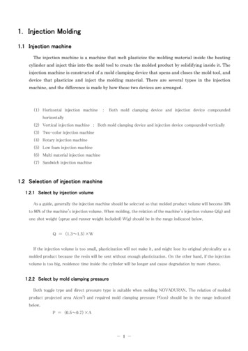
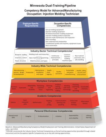
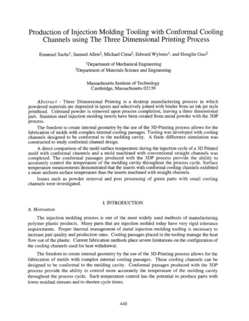
Mold and Part DesignSecondary runners should be perpendicular to the main runner,and the runner junction should be vapor-honed to remove burrs andsharp edges, and contain a cold slug well at every turn of direction.Figure 2 shows a properly sized runner system.Sprue BushingA sprue bushing with a standard 2½ included angle,approximately 42mm taper per meter (0.5 in. taper per foot)should be used. The entrance diameter of the bushing shouldalways be slightly larger than the nozzle exit orifice. To promote abalanced pressure to the runners and cavities, the exit diameterof the sprue bushing should be larger than the diameter of themain runner. Z-pin-type pullers are preferred for easy removal ofthe sprue.Figure 2 Proper Runner Sizing.CorrectRunnersCold Slug WellNo ColdSlug WellsUnbalancedFlow Length toCavitiesIn addition to proper runner sizing, the layout of the mold is also animportant consideration. A runner system should be designed to givebalanced flow to all gates, ideally designed so that the melt reaches allof the gates simultaneously.Figure 1 shows typical relative dimensions of a trapezoidal crosssection runner. The flow through a trapezoidal runner is equivalentto that of the largest circular runner whose cross-section can beinscribed within the trapezoid.TPU compounds have been molded successfully in hot-runner systems.In many cases, hot-runner mold design and temperature control havebecome the most complex part of the molding process. Hot-runnermolds have usually been designed originally for plastics other than TPU.In general, those created for PVC would offer the best characteristics forsuccess with TPU.Figure 1 Relative Dimensions of a Trapezoidal Runnerfor Use in a Three-Plate Mold.LSecondary RunnersSmaller thanMain RunnerSprue Largerthan MainRunnerIn a two-plate mold, full-round runners are preferred because theyprovide the highest volume-to-surface ratio, the least pressure dropand are the easiest to eject from the mold. Depending on the partsize and weight, typical full-round runner diameters are 0.6 cm to 1.0cm (0.25 in. to 0.4 in.). Because of excessive flow restriction, smalldiameter runners, less than 0.6 cm (0.25 in.) diameter, should beavoided. Excessively large-diameter runners offer little advantageand contribute to longer cycle times and greater material usage.If a three-plate mold is being used, full-round runners are stillpreferred, but trapezoidal runners can be used.UndesirableWCold Slug WellsDuring injection, the initial surge of material is generally cool since ithas remained dormant in the nozzle while the previous shot was beingejected from the mold. To prevent this cold material from entering thecavity and causing a visual defect, cold slug wells or runoffs should beincorporated into the runner system before material is allowed to enterthe cavities. Properly sized runner systems designed for balanced flowwhich incorporate cold slug wells are shown in Figure 3./3W2¾WTo maintain pressure and balanced flow during injection into amultiple cavity or multigated mold, the secondary runners should beslightly smaller in cross section than the main runner.4
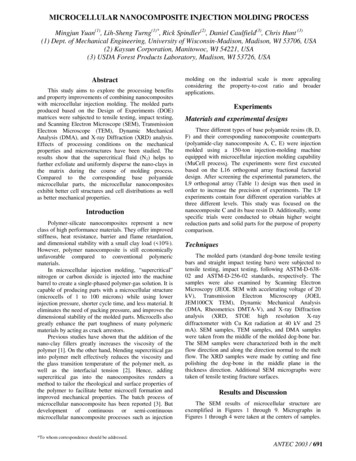
P O LY M E RFigure 3 Runner Systems with Balanced-FlowS O L U T I O N STab gates are strongly recommended for the softer TPU grades.They eliminate the distortion in the gate area that commonly occurswith very flexible materials. The use of pinpoint gates and tunnelgates should be restricted to very small parts of a few ounces or lessin weight where the flow length from the gate is less than two inches.The land length for gates should always be as short as possible. Agood rule of thumb for determining the proper land length is that itshould be no greater than one-half the gate thickness.Cavity Layouts and Cold Slug Wells.In multigated cavities, the gate location and number of gates arevery important in relation to the appearance and performance ofthe molded part. Since gate areas are almost always more highlystressed due to orientation, gates should be located in noncriticalsections of the part. Gating in thick sections of the part and allowingthe material to flow to the thinner sections keep sink marks to aminimum. When gating into a thick section, the flow should bedirected toward a cavity wall or deflector pin to break up the meltentering the cavity and to prevent a condition called “worming.”Worming is a random pattern of weld lines opposite the gate causedby the rapid cooling of the injection melt. If the design of the partrequires a split in the flow front coming from the gate, a weld linewill usually result when the flow fronts meet. Care should be takenin designing parts to keep the number of gates to a minimum tominimize weld lines. Multiple weld lines could detract from thesurface appearance and may affect performance.GatesTPU compounds have been molded satisfactorily through awidevariety of gate designs including fan, lab, edge, submarine andsprue. In general, the gates should have a generous cross-sectionalarea to allow the material to flow freely with a minimum of pressureloss. The gates should be vapor-honed with all rough edges andsharp corners removed. Figure 4 illustrates several acceptable gatedesigns with rounded corners for minimum restriction.Mold ShrinkageFigure 4 Gate Designs.Mold design, part design and operating conditions all affect the moldshrinkage value of any thermoplastic material. In cases where veryclose tolerance must be maintained, it is suggested that a prototypetool be made before building the production tool. Where standardor coarse tolerances are all that is required,the standard moldshrinkage allowance for the particular TPU compounds should beused. It should be noted that post annealing or exposing parts to apoint over temperature will increase the mold shrinkage from what isnormally expected. This data is presented in Technical Data Sheetsof Lubrizol LifeSciences TPU molding compounds.FanGateSubmarineGatePinGateEjection of the PartTPU compounds release easily from properly prepared mold surfaces.Highly polished, chrome-plated surfaces should be avoided exceptfor simple flat parts. However, for high-clarity parts, a glossy surfaceis required. Because most parts are more complex, a vapor-honedmatte surface is recommended to provide the easiest, most troublefreerelease. An electrical discharge machining (EDM) surface can alsoprovide a suitable, easy release. Ejector pins should have as large asurface area as possible, especially those located at thick part sectionswhere the interior may still be very soft at the time of ejection.Tab GateRingGateStripper plates and air ejection systems may also be used with TPUcompounds.5
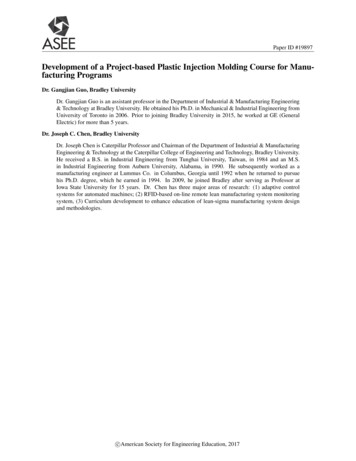
Ventsthermoplastic materials (e.g.g. nylon), LifeSciences TPU compoundsare hygroscopic (absorb water from the atmosphere). AlthoughTPU is dry when packaged, storage time and conditions andtransportation will allow moisture to enter. The amount and rate ofabsorption will depend on the type of urethane as well as the typeof storage container, temperature and humidity of the air to whichit is exposed. Excessive moisture can also cause splay, voids andparts sticking to the mold. Even if the part appearance is not beingaffected, a severe reduction of the service life of the part can beresult.Because of the low viscosity of the melt, normal vent depths of .05mm (.002 inches) and greater will allow TPU compounds to flash.Therefore, vents should be cut only after initial trials on the new toolhave indicated necessary locations. A vent channel 6.4 mm to 12.7mm (.25 in. to .50 in.) wide by .03 mm (.001 inch) deep is usuallysufficient. See Figure 5.Figure 5 Mold Venting.Mold VentDimensions:A - 0.001 to 0.002B - 0.100 to 0.150C - 0.500 typicalD - 0.400 minimumWhen moisture reacts with the TPU, the result is shorter polymerchains (lower molecular weight). Even though physical propertiesat the time of molding may be satisfactory, the reduced molecularweight may be the equivalent to years of use. For optimumappearance and part longevity, TPUs must be dry when molded.VentCAAFor a small volume of material, an oven dryer is satisfactory. The TPUcompounds should be spread in the trays one-inch deep and driedfor two hours at 105 C (220 F).DAVentBPlastic PartFeed RunWhen larger volumes of material make oven drying impractical,a dehumidifying hopper dryer is recommended. A -40 C (-40 F)maximum inlet air dewpoint is recommended. A 0.02% or lessmoisture content should be obtained before the material is molded.MoldCavityPolyurethanes are hygroscopic and will absorb moisture when thecontainers are opened to the atmosphere.PurgingThe barrel should be thoroughly purged before and after moldingTPU. Since TPU compounds purge readily from the machine, theuse of purging compounds may not be necessary. When needed,suitable purging materials are reground polystyrene, generalpurpose ABS, and acrylic molding compounds and even PE.Purging should be done immediately after the production run whilethe material is still molten. If the machine is allowed to cool to roomtemperature, purging can be more difficult because the cold materialwill stick tenaciously to the screw and, on reheating, will be difficultto remove. Slowing cooling TPU in a barrel can also crystallize withinthe barrel by an annealing process.The Molding OperationProcessing ParametersSuccessful processing of LifeSciences TPU compounds by injectionmolding is very dependent upon a wide range of variables such asmachine size, shot size, screw geometry and mold design. Due tothese factors, exact machine conditions for optimum processinghave to be determined by the processor for the system chosen.The sections that follow will outline the conditions the moldershould strive to achieve. The best processing latitude and ultimateproperties in the molded part will then be realized. Finally, startupand shutdown procedures are summarized in the Processing Guidesection. This section and the Troubleshooting Guide section shouldbe readily available to setup personnel and machine operators.Mold TemperatureMolds should be provided with good temperature control to obtainoptimum appearance and production rates. The set temperaturedepends on the particular design, operation and the TPU gradebeing used. Polyether-type polyurethane materials tend to releasebetter and set up faster when parts are cooled at a relatively slowrate. Thin-walled parts [less than 3mm (.118 in.)] require highertemperatures; thicker-walled parts require lower mold temperatures.DryersTPU compounds are fully reacted thermoplastic polyurethanematerials and will not react when exposed to atmospheric moisture.However, as with all polyurethane compounds and many other6
P O LY M E RS O L U T I O N Sbe conducted with adequate ventilation to dissipate hot vapors.Precautions should be taken to avoid being struck by hot melt. Theneedle should be jabbed into the molten plastic successively four tofive times in different locations before the actual reading is taken.Occasional wiping of the needle probe with some mold releaseagent will help prevent “freezing” of plastic on the probe during theinitial portion of the reading. If material “freezes” to the probe onthe first insertion, it acts as an insulator on the probe’s surface anderroneously low values for stock temperature will be obtained.If gassing or bubbling of the hot plastic is observed during theairshot, it generally indicates a higher-than-recommended stocktemperature is being achieved and/or excessive moisture is present.Stock temperature and moisture content should be rechecked. Themolten plastic rope should appear smooth and reasonably glossy ifthe stock temperature is near optimum.Heater Band SettingsTo achieve a given stock temperature, heater band settings dependgreatly on machine size, screw design and other settings such asbackpressure and screw RPM. Large machines typically yield stocktemperatures higher than the heater band settings.For the initial trial of TPU, an ascending barrel temperature profilefrom rear to front zones is recommended. These settings should beadjusted to achieve an airshot, stock temperature 5 C to 10 C (9 Fto 18 F) less than the final desired temperature (more heat will begenerated once the machine is cycling continuously). Since heat isbeing generated by the screw within the material, it is quite normalfor the middle and front barrel temperature zones to override thesetpoint. As long as the machine is cycling regularly, these setpointsdo not need adjustments. Carefully monitor stock temperatureduring initial startup and after any condition changes.shots and will not cause any degradation from overheating. Careshould be taken so that there are no cold spots in the nozzle area.The full length of the nozzle should be covered with heater bandsas close to the tip as possible. Inadequate coverage by the heaterbands can produce cold spots and allow some of the material to setup between shots. The result will be that the parts will contain lumpsof material that were carried into the cavity by the melt stream.Stock TemperatureThe stock temperature can be controlled by a proper combinationof the heater band settings, screw backpressure and screwRPM. To develop ultimate physical properties, it is important thatrecommendations for stock temperature be followed.Nozzle TemperatureThe nozzle should be controlled to the same temperature asthat of the melt. This will prevent material from setting up betweenshots and will not cause any degradation from overheating. Careshould be taken so that there are no cold spots in the nozzle area.The full length of the nozzle should be covered with heater bandsas close to the tip as possible. Inadequate coverage by the heaterbands can produce cold spots and allow some of the material to setup between shots. The result will be that the parts will contain lumpsof material that were carried into the cavity by themelt stream.To measure stock temperature, use an accurately calibrated needleprobe pyrometer. When making a temperature measurement witha needle pyrometer, the molten material should be injected directlyfrom the nozzle onto a piece of heavy cardboard or some otherinsulating material that will not absorb heat from the plastic. Theinjection pressure, injection speed and backpressure are normally ata lower setting for taking these airshots than when at normal cycle;therefore, a stock temperature of approximately 5 C to 10 C (9 Fto 18 F) lower than the recommended range is a good objectivewhen starting. As with any thermoplastic resin, airshots should7
Injection SpeedInjection and Holding PressuresA slow-to-moderate injection speed should be used at the start ofthe molding run and increased to the point where the part fills andno signs of weld lines or sinks exist. If the injection speed is too fast,excessive frictional heat buildup can result in velocity burning as thematerial flows through restrictions or over sharp edges.Scientific Molding or Decoupled Molding techniques based on a twostage volumetric part filling process are used most often for TPUmolding. However in some circumstances filling and packing the partcompletely on the first stage filling process is used.The amount of first-stage injection pressure (booster pressure) isrequired to fill the mold cavity will depend on the stock temperature,injection speed, mold temperature and mold design. Generally,velocities/pressures in the range of 50% to 75% maximum availableoffer the best consistency and processing latitude. It is advisableto start with lower pressures and increase to the desired pressureto avoid flashing the mold. The position for the first-stage injectionvelocity/pressure should be set to switch to the second stageholding pressure just as the part is reaching full. This should coincidewith the moment that the screw completes its relatively fast-forwardtravel, leaving a 0.3 cm to 0.6 cm (0.125 in. to 0.25 in.) cushion.This frictional heat can result in surface appearance problems, or evendegradation of the material. Injection speeds for airshots should berelatively slow since there is very little resistance to the material flow.A good rule of thumb for the injection speed is to use a time of twoseconds per inch of ram travel.Screw BackpressureThe proper value for screw backpressure will vary from machine tomachine, but generally the backpressure should be in the low end ofthe 0.3 MPa to 0.7 MPa (50 psi to 100 psi) range. Low- compressionratio screws could require backpressures to 1.4 MPa (200 psi).The second-stage injection pressure (holding pressure) should bejust enough to maintain a full part as the part cools and shrinks in thecavity. This pressure is typically one-half to two-thirds of the firststage injection pressure. Parts having thicker sections usually requiregreater holding pressure.Screw RPMFor a screw of recommended geometry, a rotating speed of 40 RPMto 50 RPM should be satisfactory; higher speeds to 75 RPM havebeen successful in some applications. Large machines generallyrequire less RPM at optimum conditions. Due to increased diameter,a larger screw has a greater circumferential velocity than a smallerscrew at a given RPM. The greater velocity promotes more shearheating of the molding compound.Overpacking the part with excessive holding pressure or time onthe first-stage injection pressure can increase molded-in stress. Thiscan be detrimental to properties. Generally, sink marks opposite thegate indicate that more injection pressure/time is needed. Once it isapparent that gates are frozen off, hold pressure can be reduced tosave on energy consumption.A small cushion must be maintained ahead of the screw tocompensate for part shrinkage as it cools under holding pressure,thus preventing sink marks. Ideally, the screw should only reach fullforward position when material movement has ceased.Cooling TimeExcept for parts with very thick sections, over 9.5 mm (3/8 in.),the time required to retract the screw after the holding pressureis released is generally sufficient for cooling harder ( 90A) TPUcompounds. The mold can be opened immediately after the screwstops. In general, the harder the compound, the faster the setuptime. The cooling time required for a 85 Shore A TPU compound, forexample, may be two to three times as long as that required for a 65Shore D TPU compound.8
P O LY M E RS O L U T I O N SStartup ProcedureThoroughly clean the injection unit by either dismantling andmechanical cleaning or by an approved purge.ColorantsLifeSciences TPUs may be colored by adding dry inorganicpigments or color concentrates. The chemistry of the carrier resinto the type of TPU being used in the process may need to be thesame. Since most TPUs commercially molded are polyester grades,off-the-shelf color concentrates may usually be based on a polyesterTPU rather than a polyether type. Having a specialty concentratemade could be required.Set temperature controllers and reduce injection pressure settings,back pressure setting and screw RPM to the lower end of theiroperating ranges.After temperature zones have stabilized, introduce the TPU pelletsinto the machine.Take air-shot stock temperatures and make adjustments totemperature settings and screw RPM to approach the desired stocktemperature. Observe the appearance of the molten plastic verycarefully at this stage. A smooth, glossy surface is indicative of agood homogeneous melt, while a bumpy rope and/or matte surfaceindicate nonhomogeneity and low melt temperature. A smoking orfrothy melt suggests that the stock temperature is too high or hasexcessive moisture. Another evidence of good melt temperatureis the ability to draw down the hot rope into a thin monofilament. Abrittle break indicates a low melt temperature. Backpressure shouldbe set to achieve adequate mixing and optimum melt temperature.Unless there is a protocol requiring that concentrates match theidentity of the resin being molded, making a special concentrate withthe same grade being used is not necessary for successful coloring.It is best if the TPU concentrate has been made from a softer TPUthan that being molded. In cases where the TPUbeing molded is a hard grade (e.g.g. 50D or higher), making a colorconcentrate can result in a masterbatch that can be difficult to meltin the machine.SummaryIn summary, to develop the ultimate physical and appearanceproperties for LifeSci
thermoplastic injection-molding equipment. This brochure is intended to provide general guidelines for equipment, procedures and molding machine conditions that will help the customer obtain the best possible performance from the the Lubrizol L