Transcription
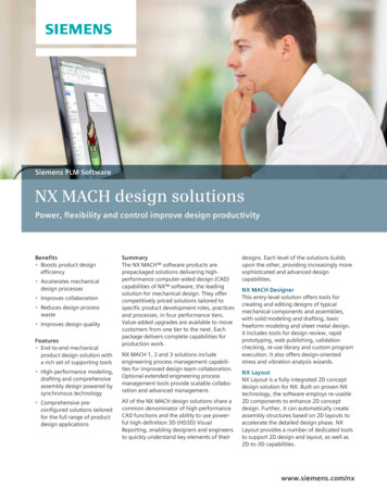
Siemens PLM SoftwareNX MACH design solutionsPower, flexibility and control improve design productivityBenefits Boosts product designefficiency Accelerates mechanicaldesign processes Improves collaboration Reduces design processwaste Improves design qualityFeatures End-to-end mechanicalproduct design solution witha rich set of supporting tools High-performance modeling,drafting and comprehensiveassembly design powered bysynchronous technology Comprehensive preconfigured solutions tailoredfor the full range of productdesign applicationsSummaryThe NX MACH software products areprepackaged solutions delivering highperformance computer-aided design (CAD)capabilities of NX software, the leadingsolution for mechanical design. They offercompetitively priced solutions tailored tospecific product development roles, practicesand processes, in four performance tiers.Value-added upgrades are available to movecustomers from one tier to the next. Eachpackage delivers complete capabilities forproduction work.NX MACH 1, 2 and 3 solutions includeengineering process management capabilities for improved design team collaboration.Optional extended engineering processmanagement tools provide scalable collaboration and advanced management.All of the NX MACH design solutions share acommon denominator of high-performanceCAD functions and the ability to use powerful high-definition 3D (HD3D) VisualReporting, enabling designers and engineersto quickly understand key elements of theirdesigns. Each level of the solutions buildsupon the other, providing increasingly moresophisticated and advanced designcapabilities.NX MACH DesignerThis entry-level solution offers tools forcreating and editing designs of typicalmechanical components and assemblies,with solid modeling and drafting, basicfreeform modeling and sheet metal design.It includes tools for design review, rapidprototyping, web publishing, validationchecking, re-use library and custom programexecution. It also offers design-orientedstress and vibration analysis wizards.NX LayoutNX Layout is a fully integrated 2D conceptdesign solution for NX. Built on proven NXtechnology, the software employs re-usable2D components to enhance 2D conceptdesign. Further, it can automatically createassembly structures based on 2D layouts toaccelerate the detailed design phase. NXLayout provides a number of dedicated toolsto support 2D design and layout, as well as2D-to-3D capabilities.www.siemens.com/nx
NXNX MACH design solutionsFeatures continued Power and flexibilitythat supports virtuallyany design methodology,whether top-down orbottom-up A cornerstone of acomplete productdevelopment system Foundation for productlifecycle management Extendible with aselection of add-onapplication modulesNX MACH 1 DesignThis solution delivers all the capabilities ofNX MACH Designer, plus a managed environment powered by Teamcenter software,with data management and visualizationcapabilities for product and processmanagement.NX MACH 2 Product DesignThe MACH 2 Product Design package provides enhanced product design capabilities,including flexible printed circuit boarddesign, validation checking, user-definedfeatures, rendering, 3D annotation forProduct and Manufacturing Information(PMI) and basic routing.NX Cool Shape DesignNX Cool Shape Design is a modeling-onlyenvironment delivering NX tools for fast andeasy development of complex shapes. NXCool Shape Design includes the advancedfreeform tools and NX Realize Shape subdivision modeling.NX MACH 3 Product DesignThe MACH 3 Product Design packageprovides a high-performance solution withNX design capabilities for advanced assemblydesign, advanced freeform modeling andsurface analysis, design optimization andmolded part validation.NX MACH 3 Industrial DesignMACH 3 Industrial Design delivers a broadrange of NX design tools, and extends thefreeform modeling capabilities with NXRealize Shape, bringing powerful subdivisionmodeling capabilities into the NXenvironment.Enhancing basic design throughproductionThe NX MACH design software packagesdeliver comprehensive and scalable digitalproduct development system from SiemensPLM Software that addresses all stages of theproduct development process, from basicdesign through production.The NX MACH packages transform theproduct development process and supportdynamic change within organizations by: Increasing innovation throughout theproduct development process Eliminating waste by better utilizing time,material and intellectual resources Improving quality from the beginningThe NX MACH design solutions offer thefollowing advantages: Unified solution – seamless applicationintegration rapidly propagates changes toproduct and associated processinformation Engineering process management – fullyintegrated, synchronized product data andprocess knowledge management Knowledge-driven automation – re-use ofproduct and process knowledge across allelements and phases of productdevelopment Integrated simulation and validation –comprehensive simulation and validationtools check product performance andmanufacturability throughout every stepof product development
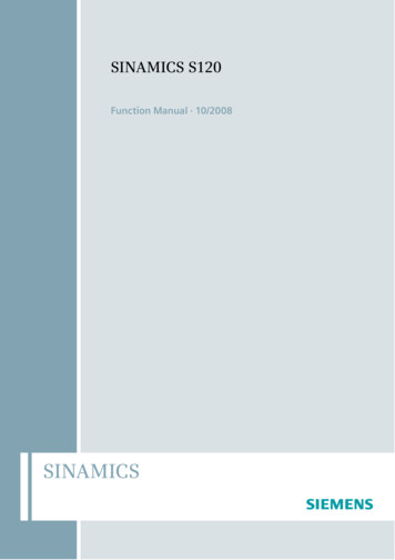
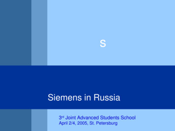
NXNX MACH design solutionsNXMACHDesignerNX MACH design capabilitiesNXLayoutNXMACH 1DesignNXMACH 2ProductDesignNXCoolShapeDesignNXMACH 3ProductDesignNXMACH 3IndustrialDesign Design modelingFeature-based solidmodelingDesignLogicUser-defined featuresAssembly designAdvanced assemblymodelingWAVE controlBasic freeform modelingAdvanced freeformmodeling Freeform shape designNX Realize ShapeProcess-specific modeling toolsSheet metal designBasic routing Flexible PCBDrafting and annotationNX LayoutDrafting GD&T, 3D annotationProduct validationHD3D Visual ReportViewing HD3D Visual ReportAuthoringProduct and datavalidation Molded Part ValidationSimulationStress and vibrationwizards Design utilitiesDesign optimizationData exchangeXpresReview collaborationWeb publishingRendering Custom programexecution Knowledge Fusion andcustom wizard execution Rapid prototypingEngineering processmanagement Design modelingFeature-based solid modelingThe core modeling capability in NXcombines wireframe, surface, solid,parametric and direct modeling ina single environment that enablesdesigners to choose the most appropriate tool for the task at hand. NXdelivers full feature-based parametric solid modeling and advancedfeatures including blends, thin-wall,draft, mirrored features, openprofile features and patterns. Inaddition, direct modeling with synchronous technology offers a fastand intuitive approach to creatingand editing designs using simplepush-and-pull methods, and enablesyou to work directly with CADgeometry created on with othersystems. For greater versatility anddesign flexibility, you can use synchronous modeling interchangeablywith all of the other modeling tools.A configurable, role-based userinterface displays the commandsyou need as you need them, andgrows as your experience levelgrows.DesignLogicDesignLogic enables users to adddesign intent or knowledge asneeded in the form of formulasand expressions. For example, adesigner may want to drive thedimensions of a feature using aformula or mathematical expression. DesignLogic allows rich controlof design parameters both atcreation time and during futuremodification.A powerful set of associative measurements allows a designer to notonly use measurements as a tool insizing and locating new features inthe design, but also monitor criticaldimensions of a design. You canalso easily add validation checks toany design parameter or associativemeasurement. These validation
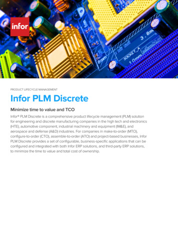
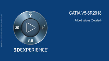
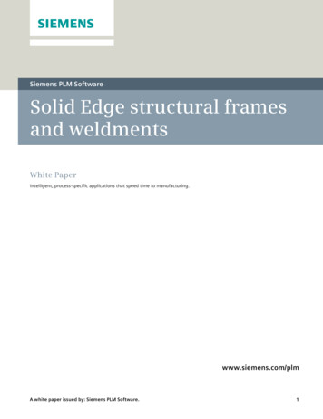
NXSynchronous technology in NX Design solutions combines the best of both parametric anddirect modeling.checks can be created on-the-fly or canbe linked to external sources of designrequirements, such as Microsoft Excel spreadsheets. Validation checks helpnotify a designer if the value of a modelexpression ever strays from appropriatelimits. Thus, DesignLogic helps adesigner create smarter, self-checkingdesigns that meet design requirements.User-defined features (UDFs)Designers using NX can capture andstore families of features for easyretrieval, editing and re-use. Userdefined features enable designers toestablish relationships between parameters, define feature variables, set defaultvalues and decide the general form thefeature will take. Existing UDFs reside ina re-use library that is accessible by anyone using NX modeling.The core assembly design tools in all NXMACH design solutions support design in theassembly context with navigation and interpart relationships.Assembly designNX assembly design supports top-downand bottom-up assembly modeling. Itprovides for rapid navigation of theassembly hierarchy and allows directaccess to the design model of any component or subassembly. It supports the“design in context” approach wherechanges can be made to any componentof the design model while working inthe context of the assembly.NX MACH design packages include toolsfor building and manipulating assemblystructures. The use of inter-part relationships enables the creation of parametricassemblies that capture and preservethe design intent whenever changesare made.Assemblies can be easily traversed usingthe assembly navigator in conjunctionwith intelligent component searchingcapabilities. NX assemblies also includesupport for the creation of flexibleassemblies and parts, enabling differentarrangements and configurations ofcomponents such as springs andpistons.Advanced assembly modelingThe advanced assembly modelingcapabilities in MACH 3 packages enableyou to simplify components or subassemblies into a single lightweight solid,to enclose assembly geometry in anenvelope of planar faces, to partitionassemblies into meaningful regions,Active mockup enables design in the fullassembly context, even with multi-CAD data.and to manage weight and other massproperties of components and assemblies. Component filtering techniquesallow users to quickly identify and loadthe components of relevance to theircurrent task, avoiding unnecessarydelays and screen clutter caused byloading irrelevant components.Assembly enveloping techniques enablethe user to represent major subassemblies as simplified abstractions to furtherreduce assembly load times and avoidthe display of unwanted or proprietaryinterior detail. The sophisticated clearance analysis and weight managementtools provided in advanced assembliesare also optimized for analyzing potential problems with fit, clearance andmass properties.Active mockupA complete digital mockup capabilityextends the toolset for building, editingand evaluating assembly models. It isespecially useful when working withlarge assemblies, but also helps improvethe productivity of most users who workregularly in an assembly context. Activemockup makes use of the standard,CAD-neutral, lightweight JT data format. This improves the performance andmemory efficiency of loading anddesigning in the context of massiveassemblies.
NXWAVE controlNX WAVE is a geometry linking tool thatenables designers to define interpartrelationships for parametric assemblymodeling. WAVE assembly control structures and constraints help simplifydesign changes and accelerate modelingof configurations, options and variants.It includes general-purpose design andmanufacturing sweeps and flanges,including dynamic law extensions, silhouette flanges, ribbons and sectionalsweeps. Designers can shape surfacesBasic freeform modelingBasic freeform modeling in NX providestools for creating complex surface andsolid models. Capabilities include: Creating solids from sheets Basic sweeping along curves Proportionally developed shapesusing 1-, 2- and 3-rail methods Lofting – ruled, curve mesh, loftedshapes using standard conic methodsand meshes of points and curvesNX design solutions include process-specificmodeling for straight-brake sheet metalcomponents. Special surface creation – surfaceextension and n-sided, bounded planeoffsetby direct point and pole manipulation,and with boundary, degree and stiffnesscontrols. Surfaces can be trimmed,extended, offset, combined, divided orenlarged. Advanced surface analysistools provide real-time graphical feedback that assists in analytical and visualevaluation of surface quality. Surface manipulation tools – surfaceextension and surface normal control Body-based trimming Surface trimming using curvesNX Realize Shape delivers fast, intuitivesubdivision modeling technology for moreefficient design of complex shapes.Advanced freeform modelingAdvanced freeform modeling extendsthe toolset to include complex filleting,blends and transition surfaces. Guidedassistance accelerates the creation ofsolids from sheets, and the softwarealso helps create surfaces from externalpoint, pole and point cloud data.Freeform shape designFreeform shape design enables designers to create conceptual surfaces forquickly capturing initial design intent,as well as creating and editing curvesdirectly on surfaces. It has direct surfacemodeling capabilities that maintainassociative surface boundary continuitycontrols ranging from G0 to G3. Styledsweeps associatively sweep profilecurves along multiple guides, andadvanced surface trimming creates cutsurfaces independent of originalsurfaces.NX Realize ShapeNX Realize Shape uses subdivisionmodeling methods to enable customers todevelop high-quality advanced 3D productforms in a fraction of the time required bytraditional tools. NX Realize Shape is fullyintegrated with other NX modeling functions, allowing advanced shapes to bebuilt and combined with traditional modeling approaches to develop advancedshapes quickly and easily.Process-specific modeling toolsSheet metal designNX provides a solids-based applicationthat is focused on design for manufacturing of sheet metal parts. Designerscan create sheet metal component models using feature-based design tools fortabs, flanges and other typical features.They can define forming tables andbend sequence tables, and reform thesolid model, taking into account material deformation properties. The sheetmetal tools generate accurate flat pattern data for downstream applications.Basic routingNX MACH 2 and 3 deliver routing capabilities that allow designers create andedit pipe, tube and cable runs. The routing capabilities also enable intelligentpart selection and placement of standard components such as elbows andtees. The routing capabilities can beextended by adding discipline-specificfunctionality for advanced applicationsincluding cabling, piping and tubing andheating, ventilation and air conditioning(HVAC).Flexible printed circuit designNX provides an environment for designof both flexible and rigid printed circuits.Based on workflows common to thedesign of printed circuit boards, theflexible printed circuit design tools helpdesigners model printed circuits rapidlyand accurately in the context of anassembly and send the outlines to manufacturing or to an ECAD system forfurther refinement. The printed circuitmodel developed in NX can be checkedfor clearances and tolerances, and thenthe finished board model can be transferred to an ECAD system for furtherrefinement, such as componentplacement or circuit trace or layerdevelopment.
NXDrafting and annotationLayout for NXNX offers tools that streamline 2Dconcept design. These includeintelligent, parametric 2D componentsthat can be dragged and dropped fromthe re-use library to accelerate creationof layouts and concepts; synchronoustechnology design tools for fast editingof 2D geometry; data conversion tools;and automated creation of 3Dassemblies from 2D layouts.NX Layout is a fully integrated 2D conceptdesign solution.DraftingNX drafting automates and streamlinesengineering drawing production. Drawings are associative to models, so modelchanges automatically update and arereflected in related drawings. Draftingcapabilities include dimensioning, symbols, tabular notes, sheet layout andplacement of standard orthographic andauxiliary views, automatic view creationfrom the 3D model, hidden line processing and automatic parts list generation.Templates that include drawing bordersand view layouts can be dragged andProduction drafting accelerates creation ofengineering drawings that are dynamicallyassociated with the 3D model.dropped into models to automate muchof the work associated with manuallycreated drawings. Drafting tools can beconfigured to comply with the drawingstandard selected by the user – ANSI,ISO, JIS, DIN, GB and ESKD.GD&T, 3D annotationWith NX, designers can capture all typesof geometry, tolerance and dimensioning information directly within the 3Dmodel, rather than on a 2D drawing. NX3D annotation associates product andmanufacturing information with the 3Dmodel, and complies with all the majorconcepts and requirements defined inthe ASME and ISO standards for 3Dproduct definition.NX quickly and accurately associatestolerance information to geometric objects via tolerance features, includingdatums, feature control block and geometric dimensioning and tolerancingsymbols. NX geometric tolerancing complies with the ASME and ISO standardsfor 3D product definition, and enforcesthe creation of standard-compliantdesigns.PMI supports the creation of dimensions, weld and surface finish symbols,material specification notes, part identification labels and a number of othermanufacturing and process-related annotations. Because the PMI is created inthe 3D CAD model and directly associated to objects in the part, the information can be easily re-used by a numberof downstream processes, from the 2DNX MACH 2 and 3 design solutions includeadvanced geometric dimensioning andtolerancing, plus 3D annotation tools foradding process and manufacturinginformation to the model.drawing to manufacturing and inspection. Incorporating PMI during the design process can enhance and shortenthe development cycle through bettercommunication, fewer errors, streamlined processes and faster change management.Product validationProduct and data validationNX validates product designs with amodel quality assurance checking utility,NX Check-Mate, which evaluates parts,assemblies and drawings to confirm that: Files comply with corporate dataquality standards Best practices for modeling andassemblies have been employed Drawings comply with internationalstandards and corporate documentation best practices Poor quality geometric data importedfrom other systems is quickly uncovered and remedied before it becomesa larger problem (for example, mismatched edges, tiny gaps in faces andnonmanifold conditions common inlower-precision modeling tools).Validation checks embedded in a designcan also help notify a designer if thevalue of a model expression ever straysfrom within appropriate limits. Thesevalidation checks can be createdon-the-fly or can be linked to externalsources of design requirements, suchas Excel spreadsheets. Companies canuse the validation checking results toestablish product quality metrics andpre-emptively head off quality issuesin the earliest stages of the development process.
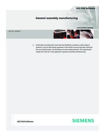
NXHD3D Visual ReportingHD3D Visual Reporting software blendsinformation of interest from your company’s data sources directly into the 3Dproduct design environment. This helpsdesigners make easier unambiguousassessments, interpret information moreaccurately and synthesize product andprocess data rapidly into correct designdecisions.NX MACH 3 design solutions include moldedpart validation that checks draft angles,undercut areas, sharp angles and wallthickness to ensure moldability.HD3D Visual Reporting comes with a setof predefined, out-of-the-box reportsthat provide your design teams withanswers to a series of commonly askedquestions. Reports related to ownership,check out, part maturity, projects, loadstatus, validation status and more areavailable for instant use. With theauthoring capability you can create andmodify your own reports to extract andpresent the data that is key to yourbusiness.HD3D visual reporting and validation toolspresent information with the 3D model for fastand intuitive interpretation.Molded part validationNX MACH 3 packages include a moldedpart validation tool that enables designers to check the moldability, even if theyknow virtually nothing about molddesign. NX analyzes parts and automatically provides designers with information about draft angles, undercut areas,sharp corners, small radiuses, and otheritems that could compromise moldingquality. It also provides designers withan easy visual check of core andcavity sides.NX MACH 3 design solutions include designoptimization that identifies key design parameters and ensures that products best meettheir design objectives.Design optimizationOptimization WizardNX offers a tool that aids in understanding which parameters are key to designobjectives. Users identify candidatevariable design parameters and a designgoal. The Optimization Wizard thenapplies sensitivity and filtering toolstogether with engineering constraints toidentify the more critical design parameters and then optimize them. Thestep-by-step wizard provides engineerswith a method to ensure that their product designs are optimized to best meetdesign goals. It also enables designersand engineers to capture engineeringrequirements, automate the explorationof alternatives and automatically identify optimized solutions.Design utilitiesData exchangeNX data exchange tools include themost commonly used translators neededto bring data into and out of NX, including IGES, STEP AP203, STEP AP214,DXF/DWG, and 2D exchange. Thesetranslators include geometry repair andsimplification capabilities to ensure themost useful data possible. All of thetranslators can be run externally fromNX or directly inside NX from “FileImport/Export” and “File Open/ Save As”or from the command line, makingthem customizable to any workflow.XpresReview collaborationFor ad hoc design reviews, theXpresReview software creates packagedfiles of lightweight design models andrelated documents that can be distributed via e-mail and viewed outside theNX environment with the freeXpresReview viewer.
NXWeb publishingNX includes an HTML publishing toolfor creating detailed documentationbased on information in NX design files.Web publishing uses template files thatcontain both HTML and special NXembedded commands. These commands extract information from adesign file and write it to an HTMLfile that can be read universally.Rapid prototypingNX enables users to automatically output model data in the faceted STLformat used with rapid prototypingtechnologies, such as stereolithographyand fused deposition. This capabilityreduces turnaround time regardless ofthe specific rapid prototyping technology employed.RenderingRendering tools in NX can be used tocommunicate designs clearly and tocreate images that can be used throughout the design and manufacturingprocesses. Users can accurately visualizedesigns to reduce costs and shortendesign cycles, and to specify real-worldmaterials that will be used when theirproducts are manufactured.Dynamic and photorealistic rendering toolsenable designers to apply textures, colorsand lighting to visualize designs and createpresentation-quality images.Custom program executionAll NX packaged design solutions canrun custom programs that were developed with the NX Open softwaredevelopment tools.Knowledge Fusion and customwizard executionMACH design packages can runapplications created with theKnowledge Fusion knowledge-basedengineering package and programscreated with Process Studio wizardbuilding tools.Add-ons availableCustomers can extend NX MACH designsolutions with a selection of optionaladd-on modules. These add-ons enablecustomers to configure their designsolutions to specific requirements suchas specialized design tools, designintegrated simulation solutions,programming and customizationtoolkits, extended engineering processmanagement and direct translators.Applications include: Advanced and aerospace sheet metal Simulation Human modeling Customization/automation Automotive design Tool design Visual reporting and analyticsEngineering process management, powered byTeamcenter, integrates product, process andprogram management with NX design tools.Engineering process managementNX delivers a foundational product datamanagement system, powered byTeamcenter software, with NX MACH1, 2 and 3 packages. It provides basicvaulting and file check-in/check-outthat are seamlessly integrated with thedesign tools. Engineering processmanagement enables designers andengineers to organize and protect allproduct data (models, drawings andassociated documents), as well as tominimize the time they spend searchingfor product data. It also helps designteams coordinate the work of teammembers. Direct translators for other CADsystemsContactSiemens PLM SoftwareAmericas 1 314-264-8499Europe 44 (0) 1276 413200Asia-Pacific 852 2230 3308www.siemens.com/plm 2015 Siemens Product LifecycleManagement Software Inc. Siemensand the Siemens logo are registeredtrademarks of Siemens AG. D-Cubed,Femap, Fibersim, Geolus, GO PLM,I-deas, JT, NX, Parasolid,SolidEdge, Syncrofit, Teamcenter andTecnomatix are trademarks or registered trademarks of Siemens ProductLifecycle Management Software Inc.or its subsidiaries in the United Statesand in other countries. Microsoft andExcel are registered trademarks ofMicrosoft Corporation. All otherlogos, trademarks, registeredtrademarks or service marksbelong to their respective holders.5242-Y10 4/15 A
product design solution with . Knowledge-driven automation – re-use of product and process knowledge across all elements and phases of product development . the context of the assembly. NX MACH design packages include tools