Transcription
1Open Phase Conditions in TransformersAnalysis and Protection AlgorithmAmir NorouziGE Digital EnergyMarkham, ONamir.norouzi@ge.comAbstract—This paper first provides an in-depth analysis ofopen phase conditions in three phase power transformers. Itdescribes why and how, upon loss of a single phase on thehigh or primary side of a transformer, voltages and currentson the low or secondary side greatly depend not only on thewindings configuration but also sometimes on transformer’s coreconstruction as well. Some particular cases are discussed in whichdetecting a high side open phase is very difficult with currenttransformers (CT) only on the low side. Then after examinationof the secondary voltages and currents practical and reliablealgorithms are presented for identification and protection ofhigh side open phase conditions from the low side of a powertransformer. Digital simulation is used for verification of theanalysis results and the protection algorithms.I. I NTRODUCTIONOpen phase condition frequently occurs in power systems,particularly in medium voltage distribution networks (suchas 33KV or below) in rural or remote areas where brokenconductor, loose connection or a blown fuse can lead to anopen phase. Some other cases of an open phase may involvea defective contact of a circuit breaker. This is considereda series fault with a different fault current calculation andsequence networks connection than other known shunt faultssuch as LG or LLG. In addition, an open phase on one side ofa transformer can be very difficult to detect on the other sidedepending on the transformer’s core and winding configurationas well as loading level.In medium voltage distribution systems, industrial plants,and rural areas and for economic reasons often smaller transformers, such as 5MVA or below, are protected mostly on theload (low) side with the possibility of only fuses on the highside usually provided by the local utility. As will be shown,with an open phase on the high side of a transformer thereare cases that the three phase voltages and currents on the lowside could be fairly balanced, particularly in lower loadingconditions, such that neither overcurrent nor negative sequencecurrent elements can pick up a fault. In fact in lower loadingconditions, even as high as 50% , the transformer may continuenormal operation for hours and possibly longer with acceptablebalanced voltages and currents on the low side while thereis an open phase on the high side. Only in higher loadingconditions may the protection relays pick up a fault, usuallyon negative sequence or sensitive ground overcurrent.An open phase anomaly can also occur in distributedgeneration (DG). Many small DG sites, including landfill,biogas, solar and wind power generation, are located in ruralor remote areas with high chances of loss of a phase on theside of the local utility grid. With relay protection only onthe low side of the grid interconnection transformer and withcertain core or winding configurations an open phase on thegrid side may go unnoticed for a while particularly in lowerloading conditions.It may initially seem that a high side open phase in atransformer will result in imbalances on the low side withenough significance that can be detected. Further analyticalinvestigation will show the amount of imbalances of currentand voltage on the low side depends on the winding configuration as well as sometimes core construction. For instance,while in a Y - transformer (ungrounded Y) an open phasewill create major unbalance voltages and currents that can beeasily detected, in a Yg - transformer it may be very difficultto detect an open phase from the low side depending on thetransformer loading.An open phase on a transformer’s primary side will createnegative sequence current and voltage as well as groundovercurrent if it has Yg winding on the same side. Theseare the main conditions that can be used to detect a faultwhen CTs are only on the secondary side of the transformer.However, relying on the low side negative sequence or groundovercurrent for open phase detection in transformers has twodisadvantages. The first relates to the inherent inability ofthis method to detect an open phase condition in certaintransformer core and winding configurations and lower loadings, leading to a gap in transformer protective relaying. Thiswill be discussed in details in the next sections. The seconddisadvantage is that a negative sequence or ground overcurrentresponding to an open phase condition on a transformer’s highside could be unhelpful or even misleading in identifying thereal cause of the problem, without which the system may notreturn to normal operating conditions. The low side protectiverelays will not allow the system to be re-energized becauseof the persistent high negative sequence or ground currentswhich leads to protracted down time with direct and indirectfinancial losses.Therefore even in those transformer configurations that anopen phase creates substantial and detectable imbalances onthe low side finding the true cause of the protection relayoperation can be confusing and tedious, particularly in remotelocations with not an easy access to technical expertise. If theprotection relay can accurately point to the specific cause of
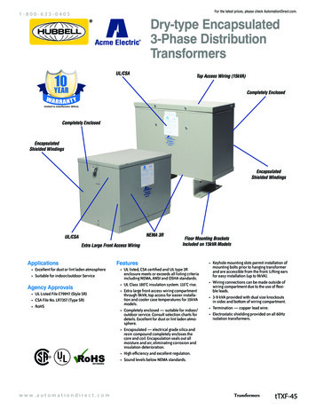
2the imbalance conditions, namely that there is an open phaseon the high side, fixing the problem will be a much easier andfaster task which will significantly reduce the down time.II. T HREE -P HASE T RANSFORMERS - A B RIEF R EVIEWIn analyzing open phase conditions in three-phase transformers we will need a basic understanding of different waystransformers are built, particularly the core construction. Whilein steady-state study of a power system we may only need toknow a transformer’s parameters, ratings and winding configuration understanding a three-phase transformer’s response toan open phase may also require further attention to its physicalconstruction.zero. As illustrated in Figure 1 in a three-leg core there is noreturn path for φ0 and it has to pass through air gap or the tankwith much higher magnetic reluctance than the core. This pathof high reluctance for φ0 in a three-leg core requires muchhigher amount of zero sequence magnetizing current whichcould lead to saturation and excessive heat. This equivalentsto a much lower zero sequence magnetizing reactance in theparallel branch of the transformer model, typically about 1 pu,which cannot be necessarily ignored when dealing with faultcurrent calculations and zero sequence networks. For comparison, the magnetizing reactance of three-phase transformersfor balanced conditions is typically 15 20 pu which can beeasily ignored in the parallel branch of a transformer model.A. Construction of Three-Phase TransformersThree-phase transformers are constructed in one of twoways: either by connecting three single phase transformersin a three-phase bank or by three sets of windings wrappedon a common core. A single core three-phase constructionis widely preferred as it is more cost effective, lighter andsmaller. However, in the older single phase bank approach eachunit may be replaced individually in the event of a failure ofthat particular unit which is an advantage over common coreconstruction.Typically the common core construction is either core typeor shell type as illustrated in Figures 1 to 4. Primary andsecondary windings can be connected as either Y or . Coretype construction consists of legs (or limbs) and yokes. Bothprimary and secondary windings of each phase are on the sameleg one on top of the other with the high voltage winding onthe outer side. This winding construction has two advantages:it makes high voltage insulation easier and it results in lessleakage flux. Yokes are the top and bottom part of the corethat joins the legs together and have no windings.Fig. 2.To provide a return path for φ0 in unbalanced systemsa fourth and even a fifth leg is added to the core typetransformers as illustrated in Figures 2 and 3. Both four andfive leg core type transformers have similar performance indealing with zero sequence flux. Five-leg core helps reducethe size of the yoke as it will carry less φ0 , thus smallertransformer size. Four and five leg transformers provide lowreluctance path for φ0 through the core with low zero sequencemagnetizing current and large magnetizing reactance.Fig. 3.Fig. 1.Four-Leg Core Type TransformerFive-Leg Core Type TransformerThree-Leg Core Type TransformerCore type construction may have 3, 4 or 5 legs withgreat impact on zero sequence flux, φ0 , and zero sequencemagnetizing current or magnetizing reactance, X0M . In abalanced power system the three phase fluxes, φa , φb andφc , are also balanced with a vector sum of zero at the yoke.However, an unbalanced power system creates zero sequenceflux as the sum of the three phase fluxes, φa φb φc , is notShell type three-phase transformer design is illustrated inFigure 4 which is a variation of five-leg core type transformer.Three phase fluxes have multiple paths within the core. Shelltype transformers provide return path for zero sequence fluxand thus demonstrate a performance similar to four or five legcore type transformers when exposed to unbalanced system,i.e. low reluctance path for φ0 and small zero sequencemagnetizing current.
3Magnitudes of induced voltage, e1 , and flux φ are linearlyproportional. With a known frequency and winding turnsequation 3 may be reduced to Vrms Kφm which is asimple linear relationship. Magnitude of the established core flux is solely determined by the magnitude of the applied voltage, itsfrequency and winding turns. In other words, if voltageV1 is applied to winding 1 magnetic flux φ is establishedin the core and similarly if flux φ passes through winding1 voltage V1 will be induced in that winding.We will revisit these observations, particularly the last one,when discussing open phase conditions in transformers. Fig. 4.Shell Type TransformerB. Fundamental Equation of Magnetic Flux in TransformersIn discussing open phase conditions in transformers we alsoneed to review the basic concept of the interaction betweenmagnetic flux and induced voltage in transformers. This willalso help understand transformer’s response to an open phase.Figure 5 shows a single phase transformer with V1 Vm cos ωt applied to the primary winding with a total numberof N1 turns with no loads on the secondary winding. Recallfrom basic theory of transformer operation that a countervoltage, e1 , will be induced in winding 1 that is almost equalto V1 provided that we assume magnetic reluctance of the core, , and winding resistance, R, are negligible. This means thatmagnetization current and voltage drop in winding 1 are verysmall which is a reasonable assumption as long as the coreis not saturated and operates within its linear magnetizationcurve.The induced voltage, e1 , will establish a magnetic flux, φ,in the core according to the Faraday’s law, i.e. e1 N1 dφdt .With the assumption of V1 e1 it follows that the flux willalso be sinusoidal and can be obtained as:Z1Vm cos ωt dt(1)φ N1 Vm2Vrmsφ sin ωt sin ωtN1 ω2πf N1(2)Therefore magnetic flux, φ, is sinusoidal with an amplitude2Vrmsof φm 2πfN1 . We can write equation 2 in the followingwell-known format:Vrms 4.44N1 f φm(3)Equation 3 is the fundamental equation that defines howvoltage and magnetic flux interact in an unloaded transformer.The assumption is again that the core is not saturated andwinding’s voltage drop is negligible which are essential to thisequation. The following important observations can be madefrom equation 3: As long as the core is not saturated and its magneticreluctance is very small if a sinusoidal voltage is appliedto one of the windings on the core it will establish asinusoidal magnetic flux within the core. Consideringthat the winding’s voltage drop is negligible the inducedvoltage e1 is equal to the applied voltage V1 .Fig. 5.Illustration of V1 , e1 and φ in an Unloaded TransformerIII. A NALYSIS OF O PEN P HASE C ONDITIONS INT HREE -P HASE T RANSFORMERSBefore presenting this analysis of open phase conditionsin three-phase transformers we need to review some basicassumptions as below: Open phase conditions or loss of a phase refers toone phase of the three phases being physically andunintentionally disconnected on the primary side of atransformer. This could occur for several reasons suchas a loose cable, a broken conductor, a blown fuse, acircuit breaker with one defective contact, etc. Primary and high side terms are used interchangeably.This is the high voltage side of the transformer which isgenerally the grid side. Secondary and low side terms are used interchangeably.This is the low voltage side of the transformer which isgenerally the load or distributed generation (DG) side. Open phase is assumed to have occurred on the primaryside of a transformer. There are no current transformers (CT) or protectionvoltage transformers (PT) on the high voltage terminalsof the transformers being discussed.First in III-A the impact of an open phase on the primarywinding are discussed independently and without consideringany magnetic or electric interaction between high and low sideof the transformer. Then in III-B with the help of the firstpart open phase conditions will be examined with completeconsideration of the interaction between the primary andsecondary sides.
4A. Primary Side Investigation (Independent From the LowSide)Grounded (Yg ) and ungrounded ( or Y ) primary windingswill respond differently to an open phase.1) Grounded Primary (Yg ): In Figure 6 with phase A openIA is zero. It is assumed that the utility grid supplying thehigh side is strong enough that upon loss of phase A voltagesof the other phases, VB and VC will essentially remain thesame.Now if the transformer is three-leg core type, as illustratedin Figure 1, the only return path for φA and φB is through thecoil of the disconnected phase A. Therefore, φA φB φCwhich is still the same as when phase A was connected tothe transformer (in balanced conditions before the phase lossφA φB φC 0). This is because from observations ofSection II-B we know magnetic flux of a winding is solelydetermined by voltage, frequency and winding turns and herewith all three parameters essentially the same before and afterthe open phase conditions φB and φC will also remain thesame. Hence the same φA is passing through winding A whichmeans the same voltage, VA , will be induced in this winding.Therefore, in a three-leg transformer with Yg primary windingsthe winding with the lost phase will have an induced voltageequal to the voltage before the open phase occurrence.still VBC and remains unchanged. However, VBC is evenlydivided between coils ωA and ωC . After the loss of phase Aand considering the dot convention the followings are true forthe coil voltages and line currents:VωB VBC(5)11VωA VωC VBC VBC 6 180 22(6)IA 0; IC IB(7)For a D11 configuration, equation 6 will become VωA VωB 12 VBC with VωC VBC .Fig. 7. Primary Winding with Phase A OpenFor an ungrounded Y primary in Figure 8 and with thesame assumption that VB and VC are the same before andafter phase A is open we will have the followings for voltagesacross each coil and line currents:VωA 0VωB VωC Fig. 6.(8)1VBC2(9)Yg Primary Winding with Phase A OpenIA 0; IC IBHowever, in other types of transformer cores upon openphase conditions either a fraction of φB and φC will passthrough winding A (4-leg, 5-leg, shell type) or there is no fluxlinkage between the phases at all (three single phase bank).In either case there is very little or no voltage induced in thewinding with lost phase.As illustrated in Figure 6 and regardless of the core type,upon loss of phase A the ground current at the neutral pointof the transformer is per below equation. We will use thisequation later in the discussions on the open phase conditionin transformers.IG 3I0 IB IC(4)2) Ungrounded Primary ( or Y ): Figure 7 illustratesa primary winding with phase A open. With an ABCphase sequence this is D1 configuration, i.e. side lags thesecondary Y side by 30 . The individual phase coils are calledωA , ωB and ωC . With phase A open the voltage across ωB is(10)Hence the following observations can be made for anungrounded primary winding, or Y , when one phase inopen: In primary the coil with no lost phases will havethe same voltage as before the open phase conditions.The other two coils will maintain half of their originalvoltages. These voltages will have the same magnitudeand phase angle although the new angle is totally different from before the loss of phase. This is regardlessof the physical construction of the transformer, whetherthree/four/five legs or three single phase bank. Besides,the remaining two coils will have currents with equalmagnitude but 180 apart. With these voltages and currents the system will be substantially unbalanced. In Y primary voltage of the coil with lost phase isalways zero regardless of the physical construction ofthe transformer. This is because the other two coils willalways have equal but opposite voltages which means
5the magnetic fluxes of the two remaining coils are alsoequal and opposite, i.e. φB φC . Therefore, in coreand shell type transformers no flux can go through anypaths, including leg A or ωA , except the path of legs Band C and part of the yokes that joints these two legs.This can be observed by examination of Figures 2 to 4.Similar to winding case, currents of the two remainingphases of the Y winding will be equal in magnitude butwith opposite direction, i.e. Ic IB .Fig. 9.Fig. 8.Y Primary Winding with Phase A OpenB. Open Phase Conditions in TransformersWith the discussion and findings of Section III-A we cannow investigate open phase conditions in transformers ingreater details with consideration of magnetic and electricalinteractions within the three-phase transformer. Heretransformers with commonly used configuration, includingYg - , -Yg , Yg -Yg , - are examined. Ungrounded Y willalso be discussed. The first letter indicates the high side ofthe transformer.1) Yg - Transformers: Yg - transformer is one of themost commonly used configurations. With Yg on the high sideeach coil is subjected to 13 or 57.7% of line voltage whichmakes it easier to insulate the primary coils. In distributedgeneration (DG) applications with the DG source on the side the grid cannot contribute to a ground fault on the DGgenerator while in case of a ground fault on the grid DGcan contribute to the fault which makes the anti-islandingprotection more practical by sensing the ground current onthe neutral of the Yg . This is a useful characteristic of thisconfiguration which makes it preferable in DG.Figure 9 illustrates a Yg - transformer with phase A openon the high side. Assuming that the high side is strong enoughthat VB and VC are almost the same after loss of phase A(except for additional voltage drop due to larger IB and ICas will be discussed later) low side coils of ωb and ωc willhave the same induced voltage as before loss of phase A. Thisis because high side coils of ωB and ωC still have the samevoltage, hence the same induced voltage on the correspondinglow side coils. Therefore, upon loss of phase A, voltage incoil a will be:Vωa Vωb Vωc(11)Open Phase in a Yg - TransformerWhich is the same as when coil a was energized from thehigh side coil A (before loss of phase A we had Vωa Vωb Vωc 0).It is important to notice that, despite discussions on Ygprimary in Section III-A1 and how similar voltage may ormay not be induced on the coil with lost phase dependingon the construction of the transformer, here Vωa and VωA arealways re-generated regardless of transformer’s construction,including three single-phase banks. This is because the interaction between the primary and secondary coils is taken intoconsideration. In fact re-generation of voltages of the coilswith lost phase is by a different mechanism than what wasdiscussed in Section III-A1.In an unloaded Yg - transformer both the high and lowside voltages corresponding to the lost phase is perfectlyre-generated such that effectively no change in three phasevoltage magnitudes and angels is seen on primary andsecondary sides. When loads are added the transformer willcontinue to supply the low side loads from all three phasesas before the phase loss with the following important notes:1) With almost the same line voltages on the low side thetransformer will supply nearly the same power to theloads.2) On the high side power is carried only by the remainingtwo phases. Therefore, the current on those phases willbe roughly 50% larger than before the loss of phase.However, since the high side is no longer a three-phasesystem new phase angles will be established. The newIB and IC will be apart considerably different from the120 of a three-phase balanced system.3) The high side coil with lost voltage and its corresponding coil on the low side do not carry any power, despiteboth coils being energized with almost the same voltage.Coil a on the low side doesn’t carry any current excepta very small current for magnetization and losses. Thisis simply because high side coil A doesn’t transfer anypower to coil a and this is the only way coil a canreceive power from the primary side. It follows thatpower being supplied to the load by phases a, b andc all come from only two coils on the low and highsides, particularly power being supplied by phase a isactually being provided only by coils b and c. We will
6Fig. 10.Single Line Diagram of the Sample Power SystemFigure 11 illustrates simulation results for an open phasecondition which occurs at t 0.1Sec. on phase A when thetransformer is lightly loaded at 60KW. Only low and highside voltages and currents are shown. Low side voltages andcurrents as well as high side voltages are very balanced afterthe loss of phase and almost the same power is being suppliedto the load. While IA 0 after phase A is lost the other twocurrents, IB and IC considerably increase to compensate forthe lost phase in order to supply the same power to the load.Further simulation results show that on the low side II21 and VV21are about 0.62% which demonstrate a quite balanced system.Transformer LV Voltages- Vab, Vbc, VcaTransformer LV Currents- Ia, Ib, Ic1.050.036pupu0.03410.0320.950.030Transformer HV Voltages- VAn, VBn, VCn0.050.10.150.2Transformer HV Currents- IA, IB, IC1.05pu0.06pusee that this is fundamentally different from three-legcore Yg -Yg transformers where the low side coil withlost phase carries current and real power because there-generated voltage comes from flux interaction, not asimple voltage build-up. Hence despite the line currentsIa , Ib and Ic being almost unchanged the current of coilsb and c are roughly 50% larger than before to supply theadditional power to be transferred by line a.4) As the loads are being added on the low side theperfect balanced voltages of the unloaded transformerwill start to become more unbalanced with line voltagesand currents being more and more unbalanced. The mainelements impacting the system balance conditions areleakage flux and voltage drop. With higher currents afterthe phase loss come larger leakage flux and voltagedrop. As the high side line currents and also low sidecoil currents will become considerably larger roughlyby a factor of 50% two types of voltage drops willappear: one is voltage drop on the feeders supplying thetransformer’s primary side which makes the high sideterminal voltages lower than before.The other voltagedrop is due to high and low side active coils carryingagain about 50% more current than before. The coilvoltage drops impact the low side terminal voltages ofthe active coils, but the coil corresponding to the lostphase doesn’t carry current and not being impacted bythe internal transformer voltage drops.To better demonstrate the above characteristics in Yg - transformers, a digital simulation using MATLAB’s Simulinkwas performed. The transformer has a five-leg core, but wesaw that in Yg - this has no impact on transformer’s responseto an open phase conditions. Consider the power system ofFigure 10. Two different loading conditions are considered:a light resistive load of 60KW and a larger load of 600KW(33%).10.040.020.9500.050.1Time (Sec)0.150.2000.050.1Time (Sec)0.150.2Fig. 11. Simulation Results for a Yg - Transformer After Loss of PhaseA- Load 60KWFigure 12 illustrates simulation results for the same systemand conditions but the transformer is loaded at 600KW or33% of its rated power. Here we can see the impact of greatercurrents and the associated higher voltage drops and leakageflux on the system voltages. Although the transformer stillsupplies close to 33% of its rated power to the load after theloss of one phase the high side currents of the two remainingphases are more than 50% of the rated current. The simulationresults show that on the low side II21 and VV21 are about 5.9%,much greater than the previous lightly loaded conditions, butstill not a highly unbalanced system. After loss of phase thetransformer still delivers 96.4% of the power it was deliveringbefore the fault.Figure 13 illustrates individual coil currents on the low( ) side. As discussed earlier although coil a is energized itdoesn’t carry any current (except for the magnetizing currentand losses) and power after loss of phase. All three phases onthe low side receive power from only the two remaining coils.The protection elements that may seem to be applicableto open phase conditions on the transformer’s low side aremainly negative sequence voltage or current as well as groundovercurrent. From the above discussions and example we seethat in a Yg - transformer negative sequence quantities arequite low and may not necessarily be relied on for open phaseconditions. The other protection element, ground overcurrent,is meant to be used for ground faults on the grid side ofthe transformer and hence is usually set somewhat belowthe ground fault level which is most of the time considerably higher than the transformer’s rated phase current. Fromequation 4 we know that the ground current of the Yg isIG IB IC upon loss of phase A. However, this isnot a conventional three-phase system with current vectors120 apart. Assuming that upon loss of a phase the high sidecurrentswill rise about 50%, ground current, IG , is roughly 3 times the phase current, and that the ground overcurrent
7is set 50% higher than the transformer’s full load current wecan estimate that if transformer’s pre-fault current is up toabout 60% of its rated current ground overcurrent element willnot pick any fault. This is why this protection element is notreliable either in dealing with open phase conditions. Even ifground overcurrent detects a fault there is little indication thatthe fault is actually due to an open phase and not a groundfault.Transformer LV Voltages Vab, Vbc, VcaTransformer LV Currents- Ia, Ib, Ic1.10.4pupu10.30.90.80.2Transformer HV Voltages- VAn, VBn, VCnTransformer HV Currents- IA, IB, IC1.10.6pupu10.90.80.40.200.050.1Time (Sec)0.1500.200.050.1Time (Sec)0.150.2Fig. 12. Simulation Results for a Yg - Transformer After Loss of PhaseA- Load 600KWCoil Currents- Secondary Side0.350.3pu0.20.10specific conclusions applicable to open phase conditions inany type of transformer construction and configuration andseries fault calculations don’t provide such analytical tool.Besides, fault calculation methods are not necessarily capableof handling those cases that closely depend on the physicalconstruction of the transformer such as Yg -Yg .2) Transformers with Ungrounded Primary ( or Y ):Transformers with or ungrounded Y primary demonstratesimilar characteristics upon loss of a phase regardless of thesecondary configuration or core construction. These characteristics are obtained and discussed in this section. We willsee that same protection principle can be applied to suchtransformers as -Yg , -Y , - , Y - , Y -Yg and Y -Y .What is common among all such transformers with ungrounded primary winding is that upon loss of a single phasethere will be substantial voltage unbalance on both primaryand secondary side of the transformer. As discussed in III-A2only half of the phase-phase voltage will appear on two of theprimary coils. Therefore, with considerable voltage and currentdrops protection elements such as undervoltage or negativesequence current will pick up a fault on the primary side.An example is illustrated in Figure 14 where a -Ygtransformer has an open phase A on the high side. With anungrounded primary winding, as discussed in III-A2, onlyhalf of the line voltage will be established across the twocoils associated with the lost phase on the high side, i.e. coilsωA and ωC . See equations 6. Therefore, in the correspondingsecondary coils of ωa and ωc a voltage equal to half thepre-fault voltage will be induced. While here, unlike Yg - transformers, there is no voltage re-generation and existingprotection elements will detect a fault finding the actual causeof the fault can be a challenge as none of these elements firmlysuggest an open phase condition on the high side.To further investigate such cases of open phase we canuse the following well-known equations to obtain sequencecurrents, I1 and I2 , on the high side of the transformer inFigure 14 (I0 0), where a 16 120 :1(IA aIB a2 IC )(12)31I2 (IA a2 IB aIC )3We observed that IA 0 and IC IB . Substituting inthe above equations we will have:I1 00.050.1Time (Sec)0.150.2Fig. 13.Coil Currents on the Secondary Side After Loss of Phase ALoad 600KWA note on open phase fault calculations: Open phaseis considered a series fault in power systems. Similar tothe shunt faults such as LG or LLG sequence networkconnections for series faults have also been develo
from basic theory of transformer operation that a counter-voltage, e 1, will be induced in winding 1 that is almost equal to V 1 provided that we assume magnetic reluctance of the core, , and winding resistance, R, are negligible. This means that magnetization