Transcription
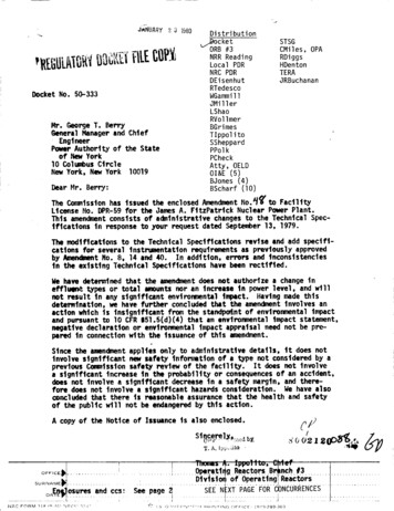
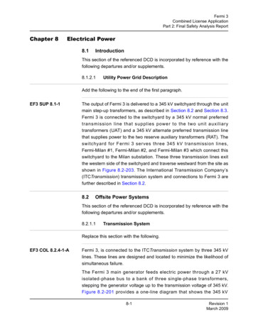
Fermi 3Combined License ApplicationPart 2: Final Safety Analysis ReportChapter 8Electrical Power8.1IntroductionThis section of the referenced DCD is incorporated by reference with thefollowing departures and/or supplements.8.1.2.1Utility Power Grid DescriptionAdd the following to the end of the first paragraph.EF3 SUP 8.1-1The output of Fermi 3 is delivered to a 345 kV switchyard through the unitmain step-up transformers, as described in Section 8.2 and Section 8.3.Fermi 3 is connected to the switchyard by a 345 kV normal preferredtransmission line that supplies power to the two unit auxiliarytransformers (UAT) and a 345 kV alternate preferred transmission linethat supplies power to the two reserve auxiliary transformers (RAT). Theswitchyard for Fermi 3 serves three 345 kV transmission lines,Fermi-Milan #1, Fermi-Milan #2, and Fermi-Milan #3 which connect thisswitchyard to the Milan substation. These three transmission lines exitthe western side of the switchyard and traverse westward from the site asshown in Figure 8.2-203. The International Transmission Company’s(ITCTransmission) transmission system and connections to Fermi 3 arefurther described in Section 8.2.8.2Offsite Power SystemsThis section of the referenced DCD is incorporated by reference with thefollowing departures and/or supplements.8.2.1.1Transmission SystemReplace this section with the following.EF3 COL 8.2.4-1-AFermi 3, is connected to the ITCTransmission system by three 345 kVlines. These lines are designed and located to minimize the likelihood ofsimultaneous failure.The Fermi 3 main generator feeds electric power through a 27 kVisolated-phase bus to a bank of three single-phase transformers,stepping the generator voltage up to the transmission voltage of 345 kV.Figure 8.2-201 provides a one-line diagram that shows the 345 kV8-1Revision 1March 2009
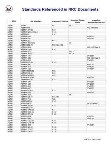
Fermi 3Combined License ApplicationPart 2: Final Safety Analysis Reportswitchyard electrical connections to the onsite power system for Fermi 3.The anticipated physical arrangement of power lines from offsite powersources is shown in Figure 8.2-202. Figure 8.2-203 maps the offsitetransmission lines.The transmission lines connecting the 345 kV switchyard for Fermi 3 tothe transmission system are as follows: A 345 kV Fermi-Milan #1 overhead line to the Milan substation(approximately 47.3 km [29.4 mi]) A 345 kV Fermi-Milan #2 overhead line to the Milan substation(approximately 47.3 km [29.4 mi]) A 345 kV Fermi-Milan #3 overhead line to the Milan substation(approximately 47.3 km [29.4 mi])The three 345 kV lines for Fermi 3 run in a common corridor, withtransmission lines for Fermi 2, to a point just east of I-75. From theintersection of this Fermi site corridor and I-75, the three Fermi-Milanlines run west and north for approximately 19.3 km (12 mi) in a corridorshared with other non-Fermi lines. From this point, all non-Fermi linesturn north and continue on to their respective destinations and the threeFermi-Milan lines continue west for approximately 16 km (10 mi) to theMilan substation.Transmission tower and steel pole separation, line installation, andclearances are consistent with applicable regulatory standards, typicallythe National Electrical Safety Code (NESC), and ITCTransmission linestandards. Design standards and parameters, including number of wires,structure heights, materials and finish are consistent withITCTransmission line design standards.8.2.1.2Offsite Power SystemReplace the first paragraph with the following.EF3 COL 8.2.4-3-AEF3 COL 8.2.4-4-AThe offsite power system is a non-safety related system. Power issupplied to Fermi 3 from three independent and physically separateoffsite power sources. The normal preferred power source is any one ofthe three 345 kV Fermi-Milan transmission lines, and the alternatepreferred power source is any other one of the three 345 kV lines.8-2Revision 1March 2009
Fermi 3Combined License ApplicationPart 2: Final Safety Analysis ReportDelete the last paragraph and add the following paragraph.Normal and alternate preferred power to the UATs and RATs,respectively, is via overhead conductors. To maintain their independencefrom each other, the conductors are routed such that they are physicallyand electrically separate from each other.8.2.1.2.1 SwitchyardReplace the last paragraph with the following.EF3 COL 8.2.4-2-AEF3 COL 8.2.4-6-AEF3 COL 8.2.4-7-AEF3 COL 8.2.4-8-AThe Fermi 3 switchyard, prior to the point of interconnection with Fermi 3,is a 345 kV, air-insulated, breaker-and-a-half bus arrangement. Fermi 3 isconnected to this switchyard by overhead conductors, the normalpreferred and alternate preferred power conductors.The anticipated physical location and electrical interconnection of the 345kV switchyard for Fermi 3 is shown on Figure 8.2-201 and Figure8.2-202.The 345 kV switchyard for Fermi 3 receives two sources of AC auxiliarypower from the 6.9 kV Plant Investment Protection (PIP) buses for thenormal preferred switchyard power center and alternate preferredswitchyard power center, as shown on DCD Figure 8.1-1. The switchyardauxiliary power system is designed with adequate equipment, standbypower, and protection to provide maximum continuity of service foroperation of the essential switchyard equipment during both normal andabnormal conditions. There are two independent sets of 125 V DCbatteries, chargers, and DC panels for the switchyard relay and controlsystems DC supply requirements. Each charger is powered from aseparate AC source with an automatic switchover to the alternate source,in the event the preferred source is lost. The distribution systems for thetwo battery systems are physically separated.Control and relay protection systems are provided. Support systems,such as grounding, raceway, lighting, AC/DC station service, andswitchyard lightning protection, are also provided.8-3Revision 1March 2009
Fermi 3Combined License ApplicationPart 2: Final Safety Analysis ReportThe anticipated capacity and electrical characteristics for switchyardequipment are as follows:Breakers345 kVEF3 COL 8.2.4-5-AMaxDesign(kV)Rated Current (A)Interrupting Currentat Max kV379.5325063 kATransmission LinesRated Current at 86 F345 kV2940 ABus WorkRated Current345 kV3660 A8.2.1.2.2 Protective RelayingThe 345 kV transmission lines are protected with redundant high-speedcommunications-assisted relay schemes and include automatic breakerreclosing. The 345 kV switchyard buses have redundant differentialprotection using separate and independent current and control circuits.Normal and alternate preferred power conductors located between theFermi 3 UATs and RATs and the 345 kV switchyard buses are protectedby dual high-speed current differential schemes.The 345 kV switchyard circuit breakers are equipped with breaker failureprotection. All of these breakers have dual trip coils. There are twoindependent DC supply systems, each with a 125 V battery and batterycharger. Each redundant protection scheme that supplies a trip signal ispowered from its redundant DC power supply and connected to aseparate trip coil.The 345 kV switchyard for Fermi 3 does not require any transformers forFermi 3. Therefore, Fermi 3 switchyard transformer protection is notrequired.EF3 SUP 8.2-28.2.1.2.3 Testing and InspectionTransmission lines are periodically inspected via an aerial inspectionprogram in accordance with the ITCTransmission inspection plan. The8-4Revision 1March 2009
Fermi 3Combined License ApplicationPart 2: Final Safety Analysis Reportinspection focuses on such items as right-of-way encroachment,vegetation management, conductor and line hardware condition, and thecondition of supporting structures.Routine switchyard inspection activities include, but are not necessarilylimited to, the following: Periodic inspection of circuit breakers Semi-annual infrared scan of substation equipment Semi-annual inspection of substation equipment Periodic relay inspectionsRoutine switchyard testing activities include, but are not necessarilylimited to, the following: 5-year relay calibration 10-year ground grid testing tionw/annualpreventativeReliability and Stability AnalysisReplace this section with the following.EF3 COL 8.2.4-9-AEF3 COL 8.2.4-10AA system impact study performed by ITCTransmission analyzed loadflow,transient stability and fault analysis for the addition of Fermi 3.(Reference 8.2-201) The base case for this analysis represented theexpected system configuration and loading in 2017 and included plannedtransmission projects that had budgetary approval at the time theanalysis was performed. The sub-transmission system used for theanalysis represented the summer for 2007 case and did not include anyplanned upgrades beyond that time. Stability analysis was performed onboth the 2017 summer peak base model and the 2017 eighty percentmodel with Fermi 3 and projected network upgrades included.The ITCTransmission system was analyzed for thermal and voltagelimitations for normal and post contingency conditions via power flowanalysis using Power Technology International Software PSS/E andMUST power flow and contingency analysis simulation tools. Theanalysis examined potential constraints such as thermal equipmentoverloads, voltage criteria violations, breakers that exceed their rated8-5Revision 1March 2009
Fermi 3Combined License ApplicationPart 2: Final Safety Analysis Reportcapabilities as well as constraints related to maintaining system stabilityand the sudden loss of single critical generation.EF3 COL 8.2.4-10AThe equipment considered is from the point of interconnection of Fermi 3to the switchyard out to the 345 kV transmission system. Maximum andminimum switchyard voltage limits established by ITCTransmission willbe applied to the 345 kV switchyard. Normal operating and abnormalprocedures exist to maintain the switchyard voltage schedule andaddress challenges to the maximum and minimum limits. Uponapproaching or exceeding a limit, these procedures verify the availabilityof required and contingency equipment and materials, direct notificationsto outside agencies, and address unit Technical Specifications actionsuntil the normal voltage schedule can be maintained. Detroit Edison willestablish a Generator Interconnection and Operation Agreement withITCTransmission and protocols for maintenance, communications,switchyard control, and system analysis sufficient to safely operate andmaintain the power station interconnection to the transmission system.ITCTransmission in conjunction with the Midwest ISO provides analysiscapabilities for both Long Term Planning and Real Time Operations.System conditions are evaluated to ensure a bounding analysis andmodel parameters are selected that are influential in determining thesystem's ability to provide offsite power adequacy. Elements included inthe analysis are system load forecasts (including sufficient margin toensure a bounding analysis over the life of the study), system generatordispatch (including outages of generators known to be particularlyinfluential in offsite power adequacy of affected nuclear units), outageschedules for transmission elements that have significant influence onoffsite power adequacy, cross-system power transfers and powerimports/exports, and system modification plans and schedules. A RealTime State Estimator is used to assist in the evaluation of actual systemconditions.The study concluded that with the additional generating capacity of Fermi3, the transmission system remains stable under the analyzed conditions,preserving the grid connection and supporting the normal and shutdownpower requirements of Fermi 3.The reliability of the overall system design is indicated by the fact thatthere have been no widespread system interruptions. Failure rates ofindividual facilities are low. Most lightning-caused outages aremomentary, with few instances of line damage. Other facilities do fail8-6Revision 1March 2009
Fermi 3Combined License ApplicationPart 2: Final Safety Analysis Reportoccasionally, but these are random occurrences, and experience hasshown that equipment specifications are adequate.Grid availability in the region over the past 20 years has been highlyreliable with minimal outages due to equipment failures.Grid stability is evaluated on an ongoing basis based on load growth, theaddition of new transmission lines, or new generation capacity.EF3 SUP 8.2-38.2.2.3Failure Modes and Effects Analysis8.2.2.3.1 IntroductionThere are no single failures that can prevent the Fermi offsite powersystem from performing its function to provide power to Fermi 3Reference 8.2-201.8.2.2.3.2 Transmission System EvaluationFermi 3 is connected to the ITCTransmission system via three 345 kVoverhead transmission lines. The normal preferred power is any one ofthe three 345 kV lines (See Subsection 8.2.1.1 and Subsection 8.2.1.2).Each 345 kV transmission line occupies a common right-of-way andtraverses from the Fermi site within an anticipated 91 m (300 ft)right-of-way. The 345 kV towers and poles provide clearances consistentwith applicable regulatory standards. The towers and poles are groundedto achieve 15 ohms or less per structure. Failure of any one 345 kV toweror pole due to structural failure can at most disrupt and cause a loss ofpower distribution to itself and the adjacent line, if one is present.Failure of a line conductor would cause the loss of one of the three 345kV lines, with the other two lines remaining available as normal andalternate preferred power sources.8.2.2.3.3 Switchyard EvaluationA breaker-and-a-half scheme is incorporated in the design of the 345 kVswitchyard for Fermi 3. The equipment in this switchyard is rated andpositioned within the bus configuration according to the following criteriain order to maintain incoming and outgoing load flow for Fermi 3. Equipment continuous current ratings are such that no singlecontingency in the switchyard (e.g., a breaker being out of service formaintenance) results in current exceeding 100 percent of thecontinuous current rating of the equipment.8-7Revision 1March 2009
Fermi 3Combined License ApplicationPart 2: Final Safety Analysis Report Interrupting duties are such that no faults occurring on the systemexceed the equipment rating. Momentary ratings are such that no faults occurring on the systemexceed the equipment momentary rating. Voltage ratings for the equipment are specified to be greater than themaximum expected operating voltage.The breaker-and-a-half switchyard arrangement offers the followingflexibility to control a failed condition within the switchyard: Any faulted transmission line into the switchyard can be isolatedwithout affecting any other transmission line. Either bus can be isolated without interruption of any transmission lineor other bus. All relay schemes used for protection of the offsite power circuits andthe switchyard equipment include primary and backup protectionfeatures. All breakers are equipped with dual trip coils. Eachprotection circuit that supplies a trip signal is connected to a separatetrip coil.The normal preferred and alternate preferred power supplies areelectrically independent and physically separate from each other, asindicated in DCD Section 8.2.3. This power source independence andphysical separation along with the isolation flexibility described above tocontrol failed conditions ensures that a minimum of one preferred sourceof power remains available to supply the load during all plant conditions.8.2.4COL Information8.2.4-1-A Transmission System DescriptionEF3 COL 8.2.4-1-AThis COL item is addressed in Subsection 8.2.1.1.8.2.4-2-A Switchyard DescriptionEF3 COL 8.2.4-2-AThis COL item is addressed in Subsection 8.2.1.2.1.8.2.4-3-A Normal Preferred PowerEF3 COL 8.2.4-3-AThis COL item is addressed in Subsection 8.2.1.2.8.2.4-4-A Alternate Preferred PowerEF3 COL 8.2.4-4-AThis COL item is addressed in Subsection 8.2.1.2.8-8Revision 1March 2009
Fermi 3Combined License ApplicationPart 2: Final Safety Analysis Report8.2.4-5-A Protective RelayingEF3 COL 8.2.4-5-AThis COL item is addressed in Subsection 8.2.1.2.2.8.2.4-6-A Switchyard DC PowerEF3 COL 8.2.4-6-AThis COL item is addressed in Subsection 8.2.1.2.1.8.2.4-7-A Switchyard AC PowerEF3 COL 8.2.4-7-AThis COL item is addressed in Subsection 8.2.1.2.1.8.2.4-8-A Switchyard Transformer ProtectionEF3 COL 8.2.4-8-AThis COL item is addressed in Subsection 8.2.1.2.1.8.2.4-9-A Stability and Reliability of the Offsite Transmission PowerSystemsEF3 COL 8.2.4-9-AThis COL item is addressed in Subsection 8.2.2.1.8.2.4-10-A Interface RequirementsEF3 COL 8.2.4-10-AThis COL item is addressed in Subsection 8.2.2.1.8.2.1References8.2-201ITCTransmission, System Impact Study Report (MISO G867),"Generation Interconnection in Monroe County, MI", July 21,2008.8-9Revision 1March 2009
Figure 8.2-201345 kV Switchyard Single-Line DiagramFermi 3Combined License Application[EF3 COL 8.2.4-1-A]8-10Revision 1March 2009
Figure 8.2-202345 kV Switchyard ArrangementFermi 3Combined License Application[EF3 COL 8.2.4-1-A]8-11Revision 1March 2009
Figure 8.2-203Transmission Line MapFermi 3Combined License Application[EF3 SUP 8.1-1]8-12Revision 1March 2009
Fermi 3Combined License ApplicationPart 2: Final Safety Analysis Report8.3Onsite Power SystemsThis section of the referenced DCD is incorporated by reference with thefollowing departures and/or supplements.8.3.2.1.1 Safety-Related Station Batteries and Battery ChargersStation BlackoutAdd the following paragraph at the end of this section.EF3 SUP 8.3-2Training and procedures to mitigate an SBO event are implemented inaccordance with Section 13.2 and , respectively. The ESBWR is apassive design and does not rely on offsite or onsite AC sources of powerfor at least 72 hours after an SBO event, as described in DCD Section15.5.5, Station Blackout. In addition, there are no nearby large powersources, such as a gas turbine or black start fossil fuel plant, that candirectly connect to the station to mitigate the SBO event. Restorationfrom an SBO event will be contingent upon power being made availablefrom any one of the following sources: Either of the station diesel generators Restoration of any one of the three 345 kV transmission linesdescribed in Section 8.2.Appendix 8A Miscellaneous Electrical SystemsThis section of the referenced DCD is incorporated by reference with thefollowing departures and/or supplements.8A.2.1DescriptionReplace DCD Section 8A.2.1 with the following.EF3 COL 8A.2.3-1-AA cathodic protection system is provided to the extent required. Thesystem is designed in accordance with the requirements of the NationalAssociation of Corrosion Engineers (NACE) Standards (DCD Reference8A-5).8-13Revision 1March 2009
Fermi 3Combined License ApplicationPart 2: Final Safety Analysis Report8A.2.3COL Information8A.2.3-1-AEF3 COL 8A.2.3-1-ACathodic Protection SystemThis COL item is addressed in Subsection 8A.2.1.8-14Revision 1March 2009
charger. Each redundant protection scheme that supplies a trip signal is powered from its redundant DC power supply and connected to a separate trip coil. The 345 kV switchyard for Fermi 3 does not require any transformers for Fermi 3. Therefore, Fermi 3 switchyard transformer protection