Transcription
NIST Special Publication 1122U. S. Department of CommerceNational Institute of Standardsand TechnologyApplied Economics OfficeEngineering LaboratoryGaithersburg, MD 20899
NIST Special Publication 1122U.S. Department of CommerceNational Institute of Standards andTechnologyApplied Economics OfficeEngineering LaboratoryGaithersburg, Maryland 20899-8603Proposed UNIFORMAT II Classification of Bridge ElementsMuthiah Kasi and Robert E. ChapmanSponsored by:National Institute of Standards and TechnologyEngineering LaboratoryMay 2011U.S. DEPARTMENT OF COMMERCEGary Locke, SecretaryNATIONAL INSTITUTE OF STANDARDS AND TECHNOLOGYPatrick D. Gallagher, Director
AbstractThis report presents a proposed UNIFORMAT II classification of bridge elements.Elemental classifications differ from traditional product-related classifications becausetheir core concept is an element that performs a given function, regardless of the designspecification, construction method, or materials used. The proposed classificationrepresents a major revision and restructuring of ASTM Standard Classification E 2103, abridge-related standard classification first issued by ASTM in 2000. The original bridgeclassification, E 2103, differed from the UNIFORMAT II elemental classificationhierarchy in several ways which limited its applicability. The major revisions to E 2103described in this report will promote its relevance, understanding, and acceptance in thebridge industry. Once approved and reissued by ASTM, the UNIFORMAT II StandardClassification of Bridge Elements, E 2103, will provide the basis for a comprehensivedata set of bridge-related costs that will enable public and private decision makers tochoose more cost-effective solutions for the design and construction of new bridges andthe maintenance and repair of existing bridges across the Nation.A set of alphanumeric designators for the proposed multi-level bridge classification isincluded. Because many users are interested in constructing databases for use in costanalyses associated with project planning, design, construction, maintenance and repair,and condition assessment, alphanumeric designators provide the basis for compiling,organizing, and referencing cost data.This report also includes a proposed list of sub-elements for bridges. The UNIFORMATII hierarchy consists of three levels: Level 1, Major Group Elements; Level 2, GroupElements; and Level 3, Individual Elements. Thus, the core concept of an elementresides at Level 3. However, because elements are major components of a constructedentity, there is often ambiguity of what exactly is included in an Individual Element andwhat should be rightfully excluded from it. Because sub-elements can be tied into a workbreakdown structure, they significantly enhance the usefulness of an elementalclassification across all project participants throughout the lifecycle of bridges and otherconstructed entities.Keywords:Bridges; construction; cost estimation; economic analysis; functional elements; life-cyclecost; risk analysis; standards; UNIFORMAT II; value engineeringiii
iv
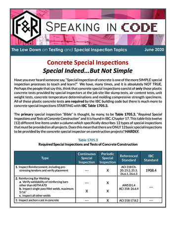
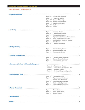
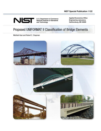
PrefaceThis report produces a proposed classification of bridge elements that will provide thebasis for a standard classification of bridge elements to be issued by ASTM International.The material presented in this report will also provide the basis for a comprehensive dataset of bridge-related costs that will enable public and private decision makers to choosemore cost-effective solutions for the design and construction of new bridges and themaintenance and repair of existing bridges across the Nation. The intended audience isthe National Institute of Standards and Technology, the bridge industry, standards andcodes developers, the American Association of State Highway and TransportationOfficials, the American Society of Civil Engineers, and other construction industrystakeholders interested in improving interdisciplinary communications and in reducingthe costs of designing, constructing, and maintaining the Nation’s physical infrastructure.DisclaimerCertain trade names and company products are mentioned in the text in order toadequately specify the technical procedures and equipment used. In no case does suchidentification imply recommendation or endorsement by the National Institute ofStandards and Technology, nor does it imply that the products are necessarily the bestavailable for the purpose.Disclaimer Regarding Non-Metrics UnitsThe policy of the National Institute of Standards and Technology is to use metric units inall of its published materials. Because this report is intended for the U.S. constructionindustry that uses U.S. customary units, it is more practical and less confusing to includeU.S. customary units as well as metric units. Measurement values in this report aretherefore stated in metric units first, followed by the corresponding values in U.S.customary units within parentheses.Cover Photographs CreditsThe cover photographs were provided by Alfred Benesch & Company.12634The bridges associated with each coverphotograph are as follows: (1) ChicagoSkyway, Chicago, Illinois; (2) GatewayArch Bridge, Taylor, Michigan; (3) AbeLincoln Memorial Bridge, LaSalle County,Illinois; (4) I-39 over Kishwaukee River,Winnebago County, Illinois;(5) USH 12over Coffee Creek, Black River Falls,Wisconsin; and (6) ghosting of theGateway Arch Bridge superstructure.5v
Author AffiliationsMuthiah Kasi, PE SE CVS, serves as Chairman of the Board at Alfred Benesch &Company. Mr. Kasi joined Alfred Benesch & Company in 1969. His experience atBenesch includes design and management of high rise and low rise buildings, long spanriver bridges and short span bridges, and urban and rural highways. Mr. Kasi is theChairman of the ASTM Subcommittee on Building Economics, where for nearly 20 yearshe has been active in developing standards covering the design, construction, andoperation of constructed facilities.Robert E. Chapman, Ph.D., is the Chief of the Applied Economics Office in theEngineering Laboratory at the National Institute of Standards and Technology (NIST).Dr. Chapman joined NIST, formerly the National Bureau of Standards, in 1975. AsChief of the Applied Economics Office, he leads a group of economists that evaluate newtechnologies, processes, government programs, legislation, and codes and standards todetermine efficient alternatives and measure their economic impacts. Since 1998, Dr.Chapman has chaired the Task Group on Techniques within the ASTM Subcommittee onBuilding Economics.vi
AcknowledgementsThe authors wish to thank all those who contributed so many excellent ideas andsuggestions for this report. They include: Dr. S. Shyam Sunder, Director of theEngineering Laboratory (EL) at the National Institute of Standards and Technology(NIST); Dr. William Grosshandler, EL Deputy Director for Building and Fire Research;Mr. Mark E. Palmer, EL’s Automated and Integrated Infrastructure ConstructionProcesses Program Manager, for their technical guidance, suggestions, and support.Special appreciation is extended to Dr. Ihab Darwish, Dr. Michael N. Goodkind, Mr.Andrew Keaschall, Mr. Robert Tipton, and Ms. Jayne Hill of Alfred Benesch &Company, for their technical contributions during the drafting and production of thismanuscript. Special appreciation is extended to Dr. Christopher U. Brown of the EL’sBuilding Environment Division and Dr. David T. Butry and Dr. Harold E. Marshall of theEL’s Applied Economics Office for their thorough reviews and many insights. Specialappreciation is extended to Ms. Jayne Hill of Alfred Benesch & Company for her coverdesign and graphics skills and to Ms. Carmen L. Pardo of the EL’s Applied EconomicsOffice for her assistance in preparing the manuscript for review and publication. Specialappreciation is also extended to Ms. Barbara Balboni, Senior Engineer RS Means; Mr.Robert P. Charette, Adjunct Professor Concordia University; Mr. Anthony L. Huxley,Construction Consultant; and Mr. Stephen Mawn, Manager Committee E06 onPerformance of Buildings ASTM International, for their comments on an earlier draft ofthis report. The report has also benefitted from the review and technical commentsprovided by Dr. Nicos S. Martys of the EL’s Materials and Construction ResearchDivision. We also acknowledge and express our gratitude to the Illinois Department ofTransportation (IDOT) for granting permission to reproduce diagrams from the IDOTBridge Standards document in Appendix B: An Illustrated Guide to the ProposedUNIFORMAT II Classification of Bridge Elements. The diagrams from the IDOTBridge Standards document reproduced in this report were in effect on March 25, 2011.We also acknowledge and express our gratitude to the Michigan Department ofTransportation for granting permission to use the Gateway Arch Bridge as a caseillustration of the proposed UNIFORMAT II classification. The case illustration ispresented in Appendix C.vii
viii
Table of ContentsAbstract . iiiPreface. vAcknowledgements . vii1 Introduction. 11.1Background . 11.2Purpose. 31.3Scope and Approach . 32 Proposed UNIFORMAT II Classification of Bridge Elements . 52.1Rationale for Classification. 52.2How the Proposed Classification will be Used . 62.3Basis of Classification. 92.4Description of Proposed UNIFORMAT II Bridge Elements . 123 Summary and Recommendations for Further Research . 313.1Summary . 313.2Recommendations for Further Research . 31References . 33Appendix A Suggested Sub-Classifications of Bridge Elements . 37Appendix B An Illustrated Guide to the Proposed UNIFORMAT II Classificationof Bridge Elements . 51Appendix C Application of Proposed UNIFORMAT II Classification and SubClassifications to a Single-Span, Modified Tied-Arch Bridge . 79C.1Summary of Key Bridge Characteristics . 79C.2Cost Accounting Framework . 85C.3Cost Analysis of the Gateway Arch Bridge Using the Proposed UNIFORMATII Elemental Classification and Sub-Classifications . 87List of FiguresFigure B.1 Major Group Elements: A Substructure, B Superstructure . 51Figure B.2 Group Elements: A10 Piers . 52Figure B.3 Group Elements: A10 Piers . 52Figure B.4 Individual Elements: A1010 Foundations (Field Requirements: A101010X1(Cofferdam)) . 53Figure B.5 Individual Elements: A1010 Foundations (Sub-Elements: A101010 SpreadFootings (Excavation)). 53Figure B.6 Individual Elements: A1010 Foundations (Sub-Elements: A101020 Piles) . 54Figure B.7 Individual Elements: A1010 Foundations (Sub-Elements: A101030 DrilledShafts) . 54Figure B.8 Individual Elements: A1020 Walls, A1030 Columns, A1040 Cap Beams . 55ix
Figure B.9 Individual Elements: A1040 Cap Beams (Sub-Elements: A10401020Reinforcement) . 55Figure B.10 Individual Elements: A1040 Cap Beams . 56Figure B.11 Group Elements: A20 Towers . 56Figure B.12 Group Elements: A30 Abutments . 57Figure B.13 Individual Elements: A3010 Foundations, A3020 Stems, A3030 Wing Walls. 57Figure B.14 Individual Elements: A3010 Foundations (Sub-Elements: A301020 Piles,A30102030 Pile Cap) . 58Figure B.15 Individual Elements: A3020 Stems . 58Figure B.16 Individual Elements: A3030 Wing Walls . 59Figure B.17 Group Elements: A40 Other Supports (Individual Elements: A4010 ThrustBlocks) . 59Figure B.18 Individual Elements: A4010 Thrust Blocks (Sub-Elements: A401020Foundations (A40102020 Piles)) . 60Figure B.19 Group Elements: B10 Short Span Assemblies (Individual Elements: B1010Flexural Member, B1020 Diaphragms), B30 Deck . 60Figure B.20 Individual Elements: B1010 Flexural Members, B1020 Diaphragms . 61Figure B.21 Individual Elements: B1020 Diaphragms . 61Figure B.22 Individual Elements: B1030 Bracings . 62Figure B.23 Individual Elements: B1030 Bracings . 62Figure B.24 Individual Elements: B1040 Bearings . 63Figure B.25 Individual Elements: B1010 Flexural Members, B1030 Bracings, B1040Bearings . 63Figure B.26 Group Elements: B20 Long Span Assemblies (Individual Elements: B2010Ribs, B2030 Hangers) . 64Figure B.27 Individual Elements: B2030 Hangers . 64Figure B.28 Individual Elements: B2010 Ribs, B2050 Ties . 65Figure B.29 Individual Elements: B2040 Spandrels. 65Figure B.30 Individual Elements: B2060 Truss Members . 66Figure B.31 Individual Elements: B2070 Segmental Box Girders . 66Figure B.32 Group Elements: B30 Deck (Individual Elements: B3010 StructuralSurface) . 67Figure B.33 Individual Elements: B3020 Wearing Surface . 67Figure B.34 Group Elements: C10 Structure Protection (Individual Elements:C1010Slope Walls) . 68Figure B.35 Individual Elements: C1020 Expansion Joints . 68Figure B.36 Individual Elements: C1030 Protection Coats . 69Figure B.37 Individual Elements: C1040 Sacrificial Beams . 69Figure B.38 Individual Elements: C1050 Drainage Systems . 70Figure B.39 Individual Elements: C1050 Drainage Systems (Sub-Elements C105030Buried Drains (C10503020 Head Walls, C10503030 End Walls)) . 70Figure B.40 Individual Elements: C1060 Inspection and Maintenance Systems . 71Figure B.41 Individual Elements: C2010 Barriers . 71Figure B.42 Group Elements: C30 Other Protection (Individual Elements: C3010Lighting) . 72x
Figure B.43 Individual Elements: C3010 Lighting, C3020 Signage . 72Figure B.44 Individual Elements: C3020 Signage . 73Figure B.45 Individual Elements: C3030 Sound Barrier Walls . 73Figure B.46 Individual Elements: C3050 Enclosure . 74Figure B.47 Major Elements: D Sitework (Group Elements: D10 Site Preparation(Individual Elements: D1010 Clearing and Grubbing)) . 74Figure B.48 Individual Elements: D1010 Clearing and Grubbing (Sub-Element D101010Clearing (Tree Removal)) . 75Figure B.49 Group Elements: D10 Site Preparation (Individual Elements: D1020Demolition and Relocation) . 75Figure B.50 Individual Elements: D1020 Demolition and Relocation . 76Figure B.51 Individual Elements: D1030 Earthwork . 76Figure B.52 Group Elements: D20 Approach Construction (Individual Elements: D2010Approach Slabs, D2020 Sleeper Slabs) . 77Figure B.53 Individual Elements: D2030 Earth Retention System . 77Figure C.154Overhead View of the Gateway Arch Bridge . 79Figure C.255Gateway Arch Bridge as Seen from Telegraph Road . 80Figure C.356Gateway Arch Bridge as Seen from I-94 . 80Figure C.457Gateway Arch Bridge Foundation System . 81Figure C.558Longitudinal View of the Arch Ribs. 82Figure C.659Transverse View of the Arch Ribs Illustrates Unequal Lengths . 83Figure C.760Access Opening to the Arch Rib. 84Figure C.861Hanger Assembly and Neoprene Transition Boots. 84Figure C.962Cost Distribution of Selected Group Elements and Individual Elements forthe Gateway Arch Bridge. 89List of TablesTable 2.1 List of Constructed Entities Suitable for Inclusion in the Family ofUNIFORMAT II Elemental Classifications . 10Table 2.2 Proposed UNIFORMAT II Classification of Bridge Elements . 11Table 2.3 Description of Proposed UNIFORMAT II Bridge Elements . 14Table A.1 Suggested Sub-Classifications of Bridge Elements . 38Table C.1 Classification Hierarchy for Program Management-Related Costs . 86Table C.2 Classification Hierarchy for Risk Management-Related Costs . 86Table C.3 Cost Analysis of the Gateway Arch Bridge Using the Proposed UNIFORMATII Elemental Classification and Sub-Classifications . 88xi
xii
1Introduction1.1BackgroundThe use of elemental classifications for improved budget planning and cost control forbuilding-related projects began shortly after the end of World War II. Elementalclassifications differ from the traditional “product-related” classifications because theircore concept is an “element” that performs a given function, regardless of the designspecification, construction method, or materials used. Thus, elemental classificationssupport a structured approach for developing budget estimates during the planning andconceptual design stages where quantity takeoffs and other product-related informationare still under development.The initial applications of elemental classifications were in the UK, where they were usedfor budgeting funds to repair educational facilities damaged or destroyed during WorldWar II and to build new facilities to meet increased demands due to population growth.The UK successes with budgeting and cost control for educational facilities led toapplications in other building types within the UK and ultimately in other parts ofEurope. By the 1960s, the use of elemental classifications for budgeting and estimatingthe costs of the design and construction of commercial and institutional buildings hadspread throughout the British Commonwealth and many other parts of the world.1The use of elemental classifications for commercial and institutional buildings in theUSA began in the 1950s. These initial applications were led by the General ServicesAdministration (GSA) and the American Institute of Architects (AIA). The interest inproducing a common framework that could be used by all stakeholders in the design,construction, and operation of commercial and institutional buildings led to the creationof UNIFORMAT in 1975.2The initial success of UNIFORMAT stimulated interest in expanding its capabilities toother types of constructed entities. In the late 1980s, a broad-based effort under theauspices of the Building Economics Subcommittee of ASTM International was launchedto produce a standard classification of building elements and related sitework.3 Theresulting standard, E 1557, was first issued by ASTM in 1993. Over the ensuing years,E 1557—refered to as UNIFORMAT II to highlight its linkage to the earlierUNIFORMAT document—has been revised and expanded to meet new and emergingneeds.41Royal Institute of Chartered Surveyors (RICS). 1969. Standard Form of Cost Analysis. London, England:The Building Cost Information Service.2Hanscomb Associates, Inc. 1975. Automated Cost Control and Estimating System. Washington, DC:General Services Administration.3Brian Bowen, Robert P. Charette, and Harold E. Marshall. 1992. UNIFORMAT II: A RecommendedClassification for Building Elements and Related Sitework, NIST Special Publication 841. Gaithersburg,MD: National Institute of Standards and Technology.4ASTM International. “Classification of Building Elements and Related Sitework—UNIFORMAT II,”E 1557, Annual Book of ASTM Standards: 2010, Vol. 4.11. West Conshohocken, PA: ASTM International.1
The latest version of E 1557 focuses primarily on buildings but has broad applicability toother types of constructed entities. Current applications of E 1557 include: planningestimates; program estimates; preliminary project descriptions; preliminary constructionschedules and cash flow projections; design phase estimates; CAD layering and buildinginformation modeling (BIM); life-cycle cost analysis reporting; checklists for technicaldesign reviews; project scheduling; construction progress reporting and interimpayments; construction claims analysis; building condition assessment; organizingdesign, engineering, and construction cost information for manuals and databases; andorganizing maintenance and life-cycle cost data.5The widespread use of E 1557—it is one of the top selling standards from ASTM’sinventory of over 12 000 standards—sparked interest in standard classifications for othertypes of constructed entities. Several ASTM standard classifications were subsequentlydeveloped, most notably a bridge-related classification, E 2103.6 However, standardclassification E 2103 differed from the underlying “elemental” concept that was at theheart of E 1557. To address the need for a more rigorous “family” of classificationstandards based on the UNIFORMAT II elemental concept, the Building EconomicsSubcommittee, ASTM E06.81, formed a task group charged with the development of aset of “Guidelines for Developing UNIFORMAT II Standard Classifications.”7 TheUNIFORMAT II Guidelines were first approved by the Building EconomicsSubcommittee in April 2009 and were posted on the ASTM E06.81 web site in May2009.8Because bridges are a critical component of the Nation’s infrastructure and many bridgesare in need of significant capital outlays over the coming years to both remedy safetyconcerns and build new capacity for multiple modes of transportation,9 a major revisionto the existing bridge classification, E 2103, is both timely and appropriate. At theOctober 2009 ASTM E06.81 meeting, a motion was passed to completely revise andrestructure E 2103 to be fully consistent with the UNIFORMAT II Guidelines document.Plans for revising and restructuring E 2103 were presented at the April 2010 and October2010 ASTM E06.81 meetings. This report expands on those plans by providing an indepth description of what the restructured version of E 2103 will include to bring it intofull compliance with the UNIFORMAT II Guidelines document. Two major extensionsto the proposed UNIFORMAT II classification of bridge elements are also presented.Once approved and reissued by ASTM, the UNIFORMAT II Standard Classification ofBridge Elements, E 2103, will provide the basis for a comprehensive data set of bridge5Robert P. Charette and Harold E. Marshall. 1999. UNIFORMAT II: Elemental Classification for BuildingSpecifications, Cost Estimating, and Cost Analysis, NISTIR 6389. Gaithersburg, MD: National Institute ofStandards and Technology.6ASTM International. “Classification of Bridge Elements and Related Approach Work,” E 2103, AnnualBook of ASTM Standards: 2010, Vol. 4.12. West Conshohocken, PA: ASTM International.7ASTM International. “Guidelines for Developing UNIFORMAT II Standard Classifications,” WorkingPaper. West Conshohocken, PA: ASTM T/E0681.htm (accessed December 2010).9ASCE 2009 Report Card for America’s Infrastructure. http://www.infrastructurereportcard.org/ (accessedDecember 2010).2
related costs that will enable public and private decision makers to choose more costeffective solutions for the design and construction of new bridges and the maintenanceand repair of existing bridges across the Nation.1.2PurposeThe purpose of this report is threefold. First and foremost, it presents a proposedUNIFORMAT II classification of bridge elements. The proposed classificationrepresents a major revision and restructuring of ASTM Standard Classification E 2103first issued in 2000 and reissued in 2006. The original bridge classification, E 2103,differed from the UNIFORMAT II elemental classification hierarchy in several wayswhich limited its applicability. The proposed major revision and restructuring presentedin this report is fully consistent with the UNIFORMAT II Guidelines documentestablished by the ASTM E06.81 Subcommittee on Building Economics. These majorrevisions to E 2103 will promote its relevance, understanding, and acceptance in thebridge industry.Second, this report includes a set of alphanumeric designators for the proposed multilevel bridge classification. Because many users are interested in constructing databasesfor use in cost analyses associated with project planning, design, construction,maintenance and repair, and condition assessment, alphanumeric designators provide thebasis for compiling, organizing, and referencing cost data. Having a common set ofalphanumeric designators promotes consistency in use among the key project participantsand other stakeholders associated with the design, construction, and use of bridges andother constructed entities.Third, this report includes a proposed list of sub-elements for bridges. As noted earlier,the primary focus of the UNIFORMAT II Standard Classification E 1557 and itsassociated family is on the elemental concept. The UNIFORMAT II hierarchy consistsof three levels: Level 1, Major Group Elements; Level 2, Group Elements; and Level 3,Individual Elements. Thus, the core concept of an element resides at Level 3. All threelevels are treated in detail in the body of this report and are intended to serve as the basisfor the proposed revisions to E 2103. However, because elements—Level 3 in aUNIFORMAT II hierarchy—are major components of a constructed entity (e.g., abridge), there is often ambiguity of what exactly is included in an Individual Element andwhat should be rightfully excluded from it. By providing a proposed set of sub-elementsas an appendix, this report lays the framework for evaluating the merits of including sucha list in E 2103 along with the other proposed revisions discussed in the body of the text.Because sub-elements can be tied into
Proposed UNIFORMAT II Classification of Bridge Elements Muthiah Kasi and Robert E. Chapman Sponsored by: National Institute of Standards and Technology Engineering Laboratory May 2011 U.S. DEPARTMENT OF COMMERCE Gary Locke, Secretary NATIONAL INSTITUTE OF STANDARDS AND TECHNOLOGY Pat