Transcription
Basics of Foundation Engineeringwith Solved ProblemsBased on “Principles of Foundation Engineering, 7th Edition”Prepared By:Ahmed S. Al-AghaSeptember -2015
Being rich is not about howmuch you have, but is about howmuch you can give
Chapter (2)Subsoil Exploration
Foundation EngineeringSubsoil ExplorationIntroduction:The soil mechanics course reviewed the fundamental properties of soils andtheir behavior under stress and strain in idealized conditions. In practice,natural soil deposits are not homogeneous, elastic, or isotropic. In someplaces, the stratification of soil deposits even may change greatly within ahorizontal distance of 15 to 30 m. For foundation design and constructionwork, one must know the actual soil stratification at a given site, thelaboratory test results of the soil samples obtained from various depths, andthe observations made during the construction of other structures built undersimilar conditions. For most major structures, adequate subsoil explorationat the construction site must be conducted.Definition:The process of determining the layers of natural soil deposits that willunderlie a proposed structure and their physical properties is generallyreferred to as subsurface exploration.Purpose of Subsurface Exploration:The purpose of subsurface exploration is to obtain information that will aidthe geotechnical engineer in:1. Determining the nature of soil at the site and its stratification.2. Selecting the type and depth of foundation suitable for a given structure.3. Evaluating the load-bearing capacity of the foundation.4. Estimating the probable settlement of a structure.5. Determining potential foundation problems (e.g., expansive soil,collapsible soil, sanitary landfill, etc.).6. Determining the location of water table.7. Determining the depth and nature of bedrock, if and when encountered.8. Performing some in situ field tests, such as permeability tests, van sheartest, and standard penetration test.9. Predicting the lateral earth pressure for structures such as retainingwalls, sheet pile, and braced cuts.Page (1)Ahmed S. Al-Agha
Foundation EngineeringSubsoil ExplorationSubsurface Exploration Program:A soil exploration program for a given structure can be divided broadly intothree phases:1. Collection of Preliminary Information:This step includes obtaining information regarding the type of structure tobe built and its general use. The following are examples explain the neededinformation about different types of structures: For the construction of building: The approximate column loads and their spacing. Local building-codes. Basement requirement. For the construction of bridge: The length of their spans. The loading on piers and abutments.2. Reconnaissance:The engineer should always make a visual inspection (field trip) of the siteto obtain information about: The general topography of the site, the possible existence of drainageditches, and other materials present at the site. Evidence of creep of slopes and deep, wide shrinkage cracks at regularlyspaced intervals may be indicative of expansive soil. Soil stratification from deep cuts, such as those made for the constructionof nearby highways and railroads. The type of vegetation at the site, which may indicate the nature of thesoil. Groundwater levels, which can be determined by checking nearby wells. The type of construction nearby and the existence of any cracks in walls(indication for settlement) or other problems. The nature of the stratification and physical properties of the soil nearbyalso can be obtained from any available soil-exploration reports onexisting structures.Page (2)Ahmed S. Al-Agha
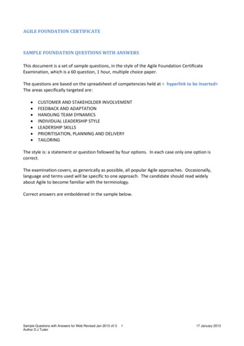
Foundation EngineeringSubsoil Exploration3. Site Investigation:This phase consists of: Planning (adopting steps for site investigation, and future vision for thesite) Making test boreholes. Collecting soil samples at desired intervals for visual observation andlaboratory tests.Determining the number of boring:There is no hard-and-fast rule exists for determining the number of boringsare to be advanced. For most buildings, at least one boring at each cornerand one at the center should provide a start. Spacing can be increased ordecreased, depending on the condition of the subsoil. If various soil strataare more or less uniform and predictable, fewer boreholes are needed than innonhomogeneous soil strata.The following table gives some guidelines for borehole spacing between fordifferent types of structures:Approximate Spacing of BoreholesType of projectSpacing (m)Multistory building10–30One-story industrial plants20–60Highways250–500Residential subdivision250–500Dams and dikes40–80Determining the depth of boring:The approximate required minimum depth of the borings should bepredetermined. The estimated depths can be changed during the drillingoperation, depending on the subsoil encountered (e.g., Rock).To determine the approximate required minimum depth of boring, engineersmay use the rules established by the American Society of Civil Engineers(ASCE 1972):1. Determine the net increase in effective stress ( σ′ ) under a foundationwith depth as shown in the Figure below.Page (3)Ahmed S. Al-Agha
Subsoil ExplorationFoundation Engineering2. Estimate the variation of the vertical effective stress (σ′o ) with depth.3. Determine the depth (D D1) at which the effective stress increase𝟏( 𝛔′ ) is equal to ( ) q (q estimated net stress on the foundation).𝟏𝟎4. Determine the depth (D D2) at which ( 𝛔′ /𝛔′𝐨 ) 𝟎. 𝟎𝟓.5. Determine the depth (D D3) which is the distance from the lower faceof the foundation to bedrock (if encountered).6. Choose the smaller of the three depths, (D1, D2, and D3), just determinedis the approximate required minimum depth of boring. σ′σ′oAfter determining the value of (D) as explained above the final depth ofboring (from the ground surface to the calculated depth) is:Dboring Df DBecause the Drilling will starts from the ground surface.Determining the value of vertical effective stress (𝛔′𝐨 ):The value of (σ′o ) always calculated from the ground surface to therequired depth, as we previously discussed in Ch.9 (Soil Mechanics).Page (4)Ahmed S. Al-Agha
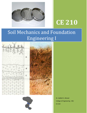
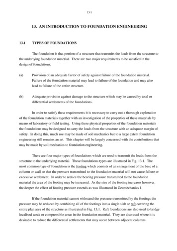
Foundation EngineeringSubsoil ExplorationDetermining the increase in vertical effective stress( 𝛔′ ):The value of ( σ′ ) always calculated from the lower face of the foundationas we discussed previously in soil mechanics course (Ch.10).An alternative approximate method can be used rather than (Ch.10) in soilmechanics course, this method is easier and faster than methods in (Ch.10).This method called (2:1 Method). The value of ( σ′ ) can be determinedusing (2:1 method) as following:According to this method, the value of ( σ′ ) at depth (D) is: σ′D PP A (B D) (L D)P the load applied on the foundation (KN).A the area of the stress distribution at 𝐝𝐞𝐩𝐭𝐡 (𝐃).Page (5)Ahmed S. Al-Agha
Foundation EngineeringSubsoil ExplorationNote that the above equation is based on the assumption that the stress fromthe foundation spreads out with a vertical-to-horizontal slope of 2:1.Now, the values of (D1 and D2) can be calculated easily as will be seen later.Note: if the foundation is circular the value of ( σ′ ) at depth (D) can bedetermined as following: σ′D PP πArea at depth (D) (B D)24P the load applied on the foundation (KN).B diameter of the foundation(m).Page (6)Ahmed S. Al-Agha
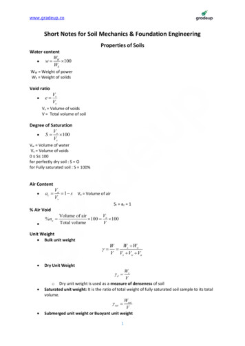
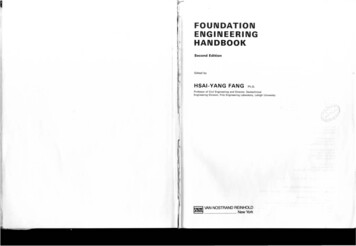
Foundation EngineeringSubsoil ExplorationIn practice: The number of boreholes and the depth of each borehole will beidentified according to the type of project and the subsoil on site, thefollowing is example for a 5 story residential building with dimensions of(40 x 70) m: The required number of boreholes 5 boreholes (one at each corner andone at the center) as mentioned previously. The depth of each borehole for this project is (8-10) m up to a depth ofwater table.The following figure shows the distribution of boreholes on the land:Page (7)Ahmed S. Al-Agha
Foundation EngineeringSubsoil ExplorationProcedures for Sampling SoilThere are two types of samples: Disturbed Samples: These types of samples are disturbed butrepresentative, and may be used for the following types of laboratory soiltests: Grain size analysis. Determination of liquid and plastic limits. Specific gravity of soil solids. Determination of organic content. Classification of soil. But disturbed soil samples cannot be used for consolidation, hydraulicconductivity, or shear tests, because these tests must be performed onthe same soil of the field without any disturbance (to berepresentative)The major equipment used to obtain disturbed sample is (Split Spoon)which is a steel tube has inner diameter of 34.93 mm and outer diameterof 50.8mm. Undisturbed Samples: These types of samples are used for thefollowing types of laboratory soil tests: Consolidation test. Hydraulic Conductivity test. Shear Strength tests.These samples are more complex and expensive, and it’s suitable forclay, however in sand is very difficult to obtain undisturbed samples.The major equipment used to obtain undisturbed sample is (Thin-WalledTube).Degree of DisturbanceIf we want to obtain a soil sample from any site, the degree of disturbancefor a soil sample is usually expressed as:D2o D2iAR (%) 100D2iAR area ratio (ratio of disturbed area to total area of soil)Page (8)Ahmed S. Al-Agha
Foundation EngineeringSubsoil ExplorationDo outside diameter of the sampling tube.Di inside diameter of the sampling tube.If (AR ) 10% the sample is 𝐮𝐧𝐝𝐢𝐬𝐭𝐮𝐫𝐛𝐞𝐝.If (AR ) 10% the sample is 𝐝𝐢𝐬𝐭𝐮𝐫𝐛𝐞𝐝.For a standard split-spoon sampler (which sampler for disturbed samples):(50.8)2 (34.93)2AR (%) 100 111.5% 10% disturbed.(34.93)2Standard Penetration Test (SPT)This test is one of the most important soil tests for geotechnical engineersbecause it’s widely used in calculating different factors as will explainedlater. This test is performed according the following procedures:1. Determining the required number and depth of boreholes in the site.2. The sampler used in SPT test is (Standard Split Spoon) which has aninside diameter of 34.39 mm and an outside diameter of 50.8 mm.3. Using drilling machine, 1.5m are drilled.4. The drilling machine is removed and the sampler will lowered to thebottom of the hole.5. The sampler is driven into the soil by hammer blows to the top of thedrill rod, the standard weight of the hammer is 622.72 N (63.48 Kg), andfor each blow, the hammer drops a distance of 76.2 cm.6. The number of blows required for a spoon penetration of three 15 cmintervals are recorded.7. The first 15 cm drive is considered as seating load and is ignored.8. The number of blows required for the last two intervals are added togive the Standard Penetration Number (N) at that depth.9. The sampler is then withdrawn and the soil sample recovered from thetube is placed in a glass bottle and transported to laboratory.10. Using the drilling machine to drill another 1.5m and then repeat theabove steps for each 1.5 m till reaching the specified depth of borehole.11.Take the average for (N) value from each 1.5 m to obtain the finalStandard Penetration Number.12.Split Spoon samples are taken at intervals (1.5m) because theses samplesare highly disturbed.Page (9)Ahmed S. Al-Agha
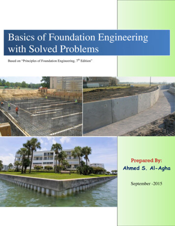
Subsoil ExplorationFoundation EngineeringDrilling MachinePage (10)Ahmed S. Al-Agha
Foundation EngineeringSubsoil ExplorationCorrection to N valueThere are several factors contribute to the variation of the standardpenetration number (N) at a given depth for similar profiles. Among thesefactors are the SPT hammer efficiency, borehole diameter, sampling method,and rod length.In the field, the magnitude of hammer efficiency can vary from 30 to 90%,the standard practice now is to express the N-value to an average energyratio of 60% (N60) (but we assume it 100%), so correcting for fieldprocedures is required as following:NηH ηB ηS ηRN60 60N measured penetration number.N60 standard penetration number, corrected for the field conditions.ηH hammer efficiency (%).ηB correction for borehole diameter.ηS sampler correction.ηR correction for rod lenght.Variations of ηH , ηB , ηS , and ηR are summarized in table 2.5 (page 84).Note: take ηH 0.6 (US safety hammer).Correlations for N60:N60 can be used for calculating some important parameters such as: Undrained shear strength (Cu) (page 84 in text book). Overconsolidation ratio (OCR) (page 85). Angle of internal friction (ϕ) (page 88 ). Relative Density (Dr )(page 87 ). Allowable bearing capacity (qall,net ) and Settlement (Se )(Ch. 5 page 263).Soil ReportDifferent soil reports will be discussed on the lecture.Page (11)Ahmed S. Al-Agha
Subsoil ExplorationFoundation EngineeringProblems:1.Site investigation is to be made for a structure of 100m length and 70mwidth. The soil profile is shown below, if the structure is subjected to 200KN/m2 what is the approximate depth of borehole (Assume𝛄𝐰 10KN/m3).γsat 18KN/m3SolutionGivens:q 200KN/m2 , structure dimensions (70 100)m P 200 (100 70) 1.4 106 KN.Df 0.0 (Structure exist on the ground surface) , γsat 18KN/m3 .D3 130m (distance from the lower face of structure to the bedrock).𝟏1. Calculating the depth (D1) at which 𝛔′𝐃𝟏 ( ) 𝐪 :𝟏𝟎11(10) q (10) 200 20KN/m2 .The following figure showing the distribution of stress under the structure atdepth (D1):Page (12)Ahmed S. Al-Agha
Subsoil ExplorationFoundation EngineeringThe increase in vertical stress ( σ′ ) at depth (D1 ) is calculated as follows:P1.4 106′ σD1 A (100 D1 ) (70 D1 )1.4 1061@ D1 σ′ ( ) q 10(100 D1 ) (70 D1 ) 20 D1 180 m. 𝛔′2. Calculating the depth (D2) at which (𝛔′𝐨) 𝟎. 𝟎𝟓 The effective stress(σ′o ) at depth D2 is calculated as following:σ′o,D2 (γsat γw ) D2 σ′o,D2 (18 10) D2 σ′o,D2 8D2 .The increase in vertical stress ( σ′ ) at depth (D2 ) is calculated as follows:P1.4 106
Foundation Engineering Subsoil Exploration Ahmed S. Al-Agha Introduction: The soil mechanics course reviewed the fundamental properties of soils and their behavior under stress and strain in idealized conditions. In practice, natural soil deposits are not homogeneous, elastic, or isotropic. In some places, the stratification of soil deposits even may change greatly within a horizontal distance .