Transcription
12 CCNP Routing and Switching SWITCH 300-115 Official Cert GuideAccess LayerKeyTopicThe access layer exists where the end users are connected to the network. Access switches usually provide Layer 2 (VLAN) connectivity between users. Devices in this layer,sometimes called building access switches, should have the following capabilities: Low cost per switch port High port density Scalable uplinks to higher layers High availability Ability to converge network services (that is, data, voice, video) Security features and quality of service (QoS)Distribution LayerKeyTopicThe distribution layer provides interconnection between the campus network’s accessand core layers. Devices in this layer, sometimes called building distribution switches,should have the following capabilities: Aggregation of multiple access layer switches High Layer 3 routing throughput for packet handling Security and policy-based connectivity functions QoS features Scalable and redundant high-speed links to the core and access layersIn the distribution layer, uplinks from all access layer devices are aggregated, or cometogether. The distribution layer switches must be capable of processing the total volumeof traffic from all the connected devices. These switches should have a high port densityof high-speed links to support the collection of access layer switches.VLANs and broadcast domains converge at the distribution layer, requiring routing, filtering, and security. The switches at this layer also must be capable of routing packets withhigh throughput.Notice that the distribution layer usually is a Layer 3 boundary, where routing meets theVLANs of the access layer.Core LayerKeyTopicA campus network’s core layer provides connectivity between all distribution layer devices. The core, sometimes referred to as the backbone, must be capable of switching trafficas efficiently as possible. Core switches should have the following attributes: Very high Layer 3 routing throughput No costly or unnecessary packet manipulations (access lists, packet filtering)
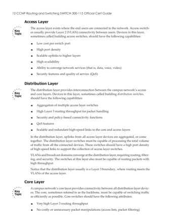
Chapter 1: Enterprise Campus Network Design 13 Redundancy and resilience for high availability Advanced QoS functionsDevices in a campus network’s core layer or backbone should be optimized for high-performance switching. Because the core layer must handle large amounts of campus-widedata, the core layer should be designed with simplicity and efficiency in mind.Although campus network design is presented as a three-layer approach (access, distribution, and core layers), the hierarchy can be collapsed or simplified in certain cases.For example, small or medium-size campus networks might not have the size or volumerequirements that would require the functions of all three layers. In that case, you couldcombine the distribution and core layers for simplicity and cost savings. When the distribution and core layers are combined into a single layer of switches, a collapsed corenetwork results.Modular Network DesignDesigning a new network that has a hierarchy with three layers is fairly straightforward.You can also migrate an existing network into a hierarchical design. The resulting network is organized, efficient, and predictable. However, a simple hierarchical design doesnot address other best practices like redundancy, in the case where a switch or a link fails,or scalability, when large additions to the network need to be added.Consider the hierarchical network shown in the left portion of Figure 1-8. Each layer ofthe network is connected to the adjacent layer by single links. If a link fails, a significantportion of the network will become isolated. In addition, the access layer switches areaggregated into a single distribution layer switch. If that switch fails, all the users willbecome essSwitch BlockFigure 1-8 Improving Availability in the Distribution and Access Layers
14 CCNP Routing and Switching SWITCH 300-115 Official Cert GuideTo mitigate a potential distribution switch failure, you can add a second, redundant distribution switch. To mitigate a potential link failure, you can add redundant links fromeach access layer switch to each distribution switch. These improvements are shown onthe right in Figure 1-8.One weakness is still present in the redundant design of Figure 1-8: The core layer hasonly one switch. If that core switch fails, users in the access layer will still be able tocommunicate with each other. However, they will not be able to reach other areas ofthe network, such as a data center, the Internet, and so on. To mitigate the effects of acore switch failure, you can add a second, redundant core switch, as shown in Figure 1-9.Redundant links should also be added between each distribution layer switch and eachcore layer switch.CoreDistributionAccessSwitch BlockFigure 1-9 Fully Redundant Hierarchical Network DesignThe redundancy needed for the small network shown in Figure 1-9 is fairly straightforward. As the network grows and more redundant switches and redundant links areadded into the design, the design can become confusing. For example, suppose manymore access layer switches need to be added to the network of Figure 1-9 because several departments of users have moved into the building or into an adjacent building.Should the new access layer switches be dual-connected into the same two distributionswitches? Should new distribution switches be added, too? If so, should each of the distribution switches be connected to every other distribution and every other core switch,creating a fully meshed network?Figure 1-10 shows one possible network design that might result. With so many interconnecting links between switches, it becomes a “brain-buster” exercise to figure out whereVLANs are trunked, what the spanning-tree topologies look like, which links should haveLayer 3 connectivity, and so on. Users might have connectivity through this network, but
Chapter 1: Enterprise Campus Network Design 15it might not be clear how they are actually working or what has gone wrong if they arenot working. This network looks more like a spider’s web than an organized, streamlineddesign.CoreDistributionAccessNew UsersNew UsersSwitch BlockFigure 1-10 Network Growth in a Disorganized FashionTo maintain organization, simplicity, and predictability, you can design a campus networkin a logical manner, using a modular approach. In this approach, each layer of the hierarchical network model can be broken into basic functional units. These units, or modules,can then be sized appropriately and connected, while allowing for future scalability andexpansion.You can divide enterprise campus networks into the following basic elements or buildingblocks:KeyTopic Switch block: A group of access layer switches, together with their distributionswitches. This is also called an access distribution block, named for the two switchlayers that it contains. The dashed rectangle in Figures 1-8 through 1-10 representtypical switch blocks. Core: The campus network’s backbone, which connects all switch blocks.Other related elements can exist. Although these elements do not contribute to the campus network’s overall function, they can be designed separately and added to the networkdesign. For example, a data center containing enterprise resources or services can have itsown access and distribution layer switches, forming a switch block that connects into thecore layer. In fact, if the data center is very large, it might have its own core switches, too,which connect into the normal campus core. Recall how a campus network is divided intoaccess, distribution, and core layers. The switch block contains switching devices fromthe access and distribution layers. The switch block then connects into the core layer,providing end-to-end connectivity across the campus. As the network grows, you can
16 CCNP Routing and Switching SWITCH 300-115 Official Cert Guideadd new access layer switches by connecting them into an existing pair of distributionswitches, as shown in Figure 1-11. You could also add a completely new access distribution switch block that contains the areas of new growth, as shown in Figure 1-12.CoreDistributionAccessSwitch BlockFigure 1-11 Network Growth by Adding Access Switches to a Switch BlockCoreDistributionAccessSwitch BlockSwitch BlockSwitch BlockFigure 1-12 Network Growth by Adding New Switch BlocksSizing a Switch BlockContaining access and distribution layer devices, the switch block is simple in concept.You should consider several factors, however, to determine an appropriate size for theswitch block. The range of available switch devices makes the switch block size very flexible. At the access layer, switch selection is usually based on port density or the numberof connected users.
Chapter 1: Enterprise Campus Network Design 17The distribution layer must be sized according to the number of access layer switchesthat are aggregated or brought into a distribution device. Consider the following factors: Traffic types and patterns Amount of Layer 3 switching capacity at the distribution layer Total number of users connected to the access layer switches Geographic boundaries of subnets or VLANsDesigning a switch block based solely on the number of users or stations containedwithin the block is usually inaccurate. Usually, no more than 2000 users should be placedwithin a single switch block. Although this is useful for initially estimating a switchblock’s size, this idea doesn’t take into account the many dynamic processes that occuron a functioning network.Instead, switch block size should be based primarily on the following: Traffic types and behavior Size and number of common workgroupsBecause of the dynamic nature of networks, you can size a switch block too large to handle the load that is placed on it. Also, the number of users and applications on a networktends to grow over time. A provision to break up or downsize a switch block might benecessary as time passes. Again, base these decisions on the actual traffic flows and patterns present in the switch block. You can estimate, model, or measure these parameterswith network-analysis applications and tools.Note The actual network-analysis process is beyond the scope of this book. Traffic estimation, modeling, and measurement are complex procedures, each requiring its own dedicated analysis tool.Generally, a switch block is too large if the following conditions are observed: The routers (multilayer switches) at the distribution layer become traffic bottlenecks.This congestion could be because of the volume of inter-VLAN traffic, intensiveCPU processing, or switching times required by policy or security functions (accesslists, queuing, and so on). Broadcast or multicast traffic slows the switches in the switch block. Broadcast andmulticast traffic must be replicated and forwarded out many ports simultaneously.This process requires some overhead in the multilayer switch, which can become toogreat if significant traffic volumes are present.
18 CCNP Routing and Switching SWITCH 300-115 Official Cert GuideSwitch Block RedundancyIn any network design, the potential always exists for some component to fail. Forexample, if an electrical circuit breaker is tripped or shuts off, a switch might lose power.A better design is to use a switch that has two independent power supplies. Each powersupply could be connected to two power sources so that one source is always likelyto beavailable to power the switch. In a similar manner, a single switch might have an internalproblem that causes it to fail. A single link might go down because a media module fails,a fiber-optic cable gets cut, and so on. To design a more resilient network, you can implement most of the components in redundant pairs.KeyTopicA switch block consists of two distribution switches that aggregate one or more accesslayer switches. Each access layer switch should have a pair of uplinks—one connecting toeach distribution switch. The physical cabling is easy to draw, but the logical connectivity is not always obvious. For example, Figure 1-13 shows a switch block that has a singleVLAN A that spans multiple access switches. You might find this where there are severalseparate physical switch chassis in an access layer room, or where two nearby communications rooms share a common VLAN. Notice from the shading how the single VLANspans across every switch (both access and distribution) and across every link connectingthe switches. This is necessary for the VLAN to be present on both access switches andto have redundant uplinks for high availability.To Core LayerLayer 3DistributionLayer 2LinksLayer 2AccessVLAN AVLAN BSwitch BlockFigure 1-13 A Redundant Switch Block DesignAlthough this design works, it is not optimal. VLAN A must be carried over every possible link within the block to span both access switches. Both distribution switches mustalso support VLAN A because they provide the Layer 3 router function for all hosts on
Chapter 1: Enterprise Campus Network Design 19the VLAN. The two distribution switches can use one of several redundant gateway protocols to provide an active IP gateway and a standby gateway at all times. These protocols require Layer 2 connectivity between the distribution switches and are discussed inChapter 18, “Layer 3 High Availability.”Notice how the shaded links connect to form two triangular loops. Layer 2 networkscannot remain stable or usable if loops are allowed to form, so some mechanism must beused to detect the loops and keep the topology loop free.In addition, the looped topology makes the entire switch block a single failure domain. Ifa host in VLAN A misbehaves or generates a tremendous amount of broadcast traffic, allthe switches and links in the switch block could be negatively impacted.A better design works toward keeping the switch block inherently free of Layer 2 loops.As Figure 1-14 shows, a loop-free switch block requires a unique VLAN on each accessswitch. In other words, VLANs are not permitted to span across multiple access switches.The extent of each VLAN, as shown by the shaded areas, becomes a V shape rather thana closed triangular loop.To Core LayerLayer 3Layer 3 LinkDistributionLayer 2LinksLayer 2AccessVLAN AVLAN BSwitch BlockFigure 1-14 Best Practice Loop-Free Switch Block TopologyKeyTopicThe boundary between Layers 2 and 3 remains the same. All Layer 2 connectivity is contained within the access layer, and the distribution layer has only Layer 3 links. Withoutany potential Layer 2 loops, the switch block can become much more stable and muchless reliant on any mechanisms to detect and prevent loops. Also, because each accessswitch has two dedicated paths into the distribution layer, both links can be fully utilizedwith traffic load balanced across them. In turn, each Layer 3 distribution switch can loadbalance traffic over its redundant links into the core layer using routing protocols.
20 CCNP Routing and Switching SWITCH 300-115 Official Cert GuideIt is also possible to push the Layer 3 boundary from the distribution layer down intothe access layer, as long as the access switches can support routing functions. Figure 1-15illustrates this design. Because Layer 3 links are used throughout the switch block, network stability is offered through the fast convergence of routing protocols and updates.Routing can also load balance packets across the redundant uplinks, making full use ofevery available link between the network layers.To Core LayerLayer 3 LinkDistributionLayer 3Layer 3LinksAccessLayer 2VLAN AVLAN BSwitch BlockFigure 1-15 A Completely Routed Switch BlockYou should become familiar with a few best practices that can help with a redundant hierarchical network design: Design each layer with pairs of switches. Connect each switch to the next higher layer with two links for redundancy. Connect each pair of distribution switches with a link, but do not connect the accesslayer switches to each other (unless the access switches support some other means tofunction as one logical stack or chassis). Do not extend VLANs beyond distribution switches. The distribution layer shouldalways be the boundary of VLANs, subnets, and broadcasts. Although Layer 2switches can extend VLANs to other switches and other layers of the hierarchy, thisactivity is discouraged. VLAN traffic should not traverse the network core.Network CoreA core layer is required to connect two or more switch blocks in a campus network.Because all traffic passing to and from all switch blocks must cross the core, the core
Chapter 1: Enterprise Campus Network Design 21layer must be as efficient and resilient as possible. The core is the campus network’s basicfoundation and carries much more traffic than any other switch block.Recall that both the distribution and core layers provide Layer 3 functionality. Preferably,the links between distribution and core layer switches should be Layer 3 routed interfaces. You can also use Layer 2 links that carry a small VLAN bounded by the two switches.In the latter case, a Layer 3 switch virtual interface (SVI) is used to provide routing withineach small VLAN.The links between layers should be designed to carry the amount of traffic load handledby the distribution switches, at a minimum. The links between core switches should beof sufficient size to carry the aggregate amount of traffic coming into one of the coreswitches. Consider the average link utilization, but allow for future growth. An Ethernetcore allows simple and scalable upgrades of magnitude; consider the progression fromGigabit Ethernet to 10-Gigabit Ethernet (10GE), and so on.KeyTopicA core should consist of two multilayer switches that connect two or more switch blocksin a redundant fashion. A redundant core is sometimes called a dual core because it isusually built from two identical switches. Figure 1-16 illustrates the core. Notice that thiscore appears as an independent module and is not merged into any other block or layer.CoreDistributionAccessSwitch BlockSwitch BlockFigure 1-16 A Redundant Core LayerRedundant links connect each switch block’s distribution layer portion to each of thedual core switches. The two core switches connect by a common link.With a redundant core, each distribution switch has two equal-cost paths into the core,allowing the available bandwidth of both paths to be used simultaneously. Both paths
22 CCNP Routing and Switching SWITCH 300-115 Official Cert Guideremain active because the distribution and core layers use Layer 3 devices that can manage equal-cost paths in routing tables. The routing protocol in use determines the availability or loss of a neighboring Layer 3 device. If one switch fails, the routing protocolreroutes traffic using an alternative path through the remaining redundant switch.If the campus network continues to grow to the point that it spans two large buildings ortwo large locations, the core layer can be replicated, as shown in Figure 1-17. Notice howthe two-node redundant core has been expanded to include four core switches. This isknown as a multinode core. Each of the four core switches is connected to the other coreswitches to form a fully meshed core layer.Switch BlockSwitch BlockAccessDistributionMulti-Node CoreDistributionAccessSwitch BlockSwitch BlockFigure 1-17 Using a Multi-Node Core in a Very Large Campus Network
Chapter 1: Enterprise Campus Network Design 23Even though the multinode core is fully meshed, the campus network is still divided acrossthe two pairs of core switches. Each switch block has redundant connections to only onecore pair—not to all of the core switches.Collapsed CoreShould all networks have a distinct redundant core layer? Perhaps not, in smaller campus networks, where the cost and scalability of a separate core layer is not warranted. A collapsedcore block is one in which the hierarchy’s core layer is collapsed into the distribution layer.Here, both distribution and core functions are provided within the same switch devices.Figure 1-18 shows the basic collapsed core design. Although the distribution and core layerfunctions are performed in the same device, keeping these functions distinct and properlydesigned is important. Note also that the collapsed core is not an independent building blockbut is integrated into the distribution layer of the individual standalone switch blocks.Switch BlockAccessDistributionCollapsed CoreDistributionAccessSwitch BlockFigure 1-18 A Collapsed Core Network DesignIn the collapsed core design, each access layer switch has a redundant link to each distribution layer switch. All Layer 3 subnets present in the access layer terminate at the distribution
24 CCNP Routing and Switching SWITCH 300-115 Official Cert Guideswitches’ Layer 3 ports, as in the basic switch block design. The distribution switches connect to each other with redundant links, completing a path to use during a failure.Core Size in a Campus NetworkThe core layer is made up of redundant switches and is bounded and isolated by Layer3 devices. Routing protocols determine paths and maintain the core’s operation. As withany network, you must pay some attention to the overall design of the routers and routing protocols in the network. Because routing protocols propagate updates throughoutthe network, network topologies might be undergoing change. The network’s size (thenumber of routers) then affects routing protocol performance as updates are exchangedand network convergence takes place.Although the network shown previously in Figure 1-16 might look small, with only twoswitch blocks of two Layer 3 switches (route processors within the distribution layerswitches) each, large campus networks can have many switch blocks connected into thecore. If you think of each multilayer switch as a router, you will recall that each routeprocessor must communicate with and keep information about each of its directly connected peers. Most routing protocols have practical limits on the number of peer routers that can be directly connected on a point-to-point or multiaccess link. In a networkwith a large number of switch blocks, the number of connected routers can grow quitelarge. Should you be concerned about a core switch peering with too many distributionswitches?No, because the actual number of directly connected peers is quite small, regardless ofthe campus network size. Access layer VLANs terminate at the distribution layer switches(unless the access layer is configured for Layer 3 operation). The only peering routersat that boundary are pairs of distribution switches, each providing routing redundancyfor each of the access layer VLAN subnets. At the distribution and core boundary, eachdistribution switch connects to only two core switches over Layer 3 switch interfaces.Therefore, only pairs of router peers are formed.When multilayer switches are used in the distribution and core layers, the routing protocols running in both layers regard each pair of redundant links between layers as equalcost paths. Traffic is routed across both links in a load-sharing fashion, utilizing the bandwidth of both.One final core layer design point is to scale the core switches to match the incoming load.At a minimum, each core switch must handle switching each of its incoming distributionlinks at 100 percent capacity.Cisco Products in a Hierarchical Network DesignBefore delving into the design practices needed to build a hierarchical campus network,you should have some idea of the actual devices that you can place at each layer. Cisco hasswitching products tailored for layer functionality and for the size of the campus network.For the purposes of this discussion, a large campus can be considered to span acrossmany buildings. A medium campus might make use of one or several buildings, and asmall campus might have only a single building.
Chapter 1: Enterprise Campus Network Design 25Choose your Cisco products based on the functionality that is expected at each layer ofa small, medium, or large campus. Do not get lost in the details of the tables. Rather, tryto understand which switch fits into which layer for a given network size.In the access layer, high port density, Power over Ethernet (PoE), and low cost are usually desirable. The Catalyst 2960-X, 3650, and 3850 switches provide 48 ports each. Likeswitch models can be connected to form a single logical switch when a greater number ofports is needed. The Catalyst 4500E is a single-switch chassis that can be populated witha variety of line cards. It also offers a choice of redundant supervisor modules that offerredundancy and even the ability to perform software upgrades with no impact to theproduction network. Table 1-3 describes some Cisco switch platforms that are commonlyused in the access layer.Table 1-3 Common Access Layer Switch PlatformsCatalyst Max PortModelDensityUplinksMaxOtherBackplane Features2960-X384 (Upto8 48-portswitches ina stack)2 10GE or 80 Gbps4 1 GigabitEthernetper switch3650432 (Upto9 48-portswitches ina stack)2 GigabitEthernetor 4 10GE160 sscontroller,PoE 3850432 (Upto9 48-portswitches ina stack)4 Gigabit 480 GbpsEthernet, esscontroller,PoE , UPoE4500E384 (Up to8 48-portmodulesper chassis)Up to12-port10GE permodule928 GbpsRIP, OSPFavailable forrouted accesslayer; PoE gratedwirelesscontroller,PoE , UPoE
26 CCNP Routing and Switching SWITCH 300-115 Official Cert GuideThe distribution and core layers are very similar in function and switching features.Generally, these layers require high Layer 3 switching throughput and a high density ofhigh-bandwidth optical media. Cisco offers the Catalyst 3750-X, 4500-X, 4500E, and6800, as summarized in Table 1-4.Table 1-4 Common Distribution and Core Layer Switch PlatformsCatalystModelMax PortDensityMaxOther FeaturesBackplane4500-X80 10GE1.6 Tbps4500E96 10GE or 384 928 GbpsGigabit EthernetDual supervisors6807-XL 4040Gbps, 16022.8 TbpsGigabit Ethernet,480 GigabitEthernetDual supervisor,dual-chassis VSSredundancyDual-chassisVirtualSwitchingSystem (VSS)redundancy
Chapter 1: Enterprise Campus Network Design 27Exam Preparation TasksReview All Key TopicsReview the most important topics in the chapter, noted with the Key Topic icon in theouter margin of the page. Table 1-5 lists a reference of these key topics and the page numbers on which each is found.KeyTopicTable 1-5 Key Topics for Chapter 1Key Topic Element DescriptionPage NumberParagraphDescribes the Cisco hierarchical network designprinciples9ParagraphDescribes the access layer12ParagraphDescribes the distribution layer12ParagraphDescribes the core layer12ParagraphExplains modular network design using switchblocks15ParagraphDiscusses the pitfalls of letting VLANs span accesslayer switches18ParagraphDiscusses two best practice designs for switch block 19redundancyParagraphExplains a redundant core design21Complete Tables and Lists from MemoryThere are no memory tables in this chapter.Define Key TermsDefine the following key terms from this chapter, and check your answers in the glossary:hierarchical network design, access layer, distribution layer, core layer, switch block,collapsed core, dual core
28 CCNP Routing and Switching SWITCH 300-115 Official Cert GuideThis chapter covers the following topics that youneed to master for the CCNP SWITCH exam: Layer 2 Switch Operation: This section describesthe functionality of a switch that forwards Ethernetframes. Multilayer Switch Operation: This sectiondescribes the mechanisms that forward packets atOSI Layers 3 and 4. Tables Used in Switching: This section explainshow tables of information and computation are usedto make switching decisions. Coverage focuses onthe content-addressable memory table involved inLayer 2 forwarding, and the ternary content-addressable memory used in packet-handling decisions atLayers 2 through 4. Managing Switching Tables: This section reviewsthe Catalyst commands that you can use to configure and monitor the switching tables and memory.You will find these commands useful when troubleshooting or tracing the sources of data or problemsin a switched network.
Chapter 9: Advanced Spanning Tree Protocol 231Example 9-1 Detecting a Neighboring Switch’s STP TypeSwitch# show spanning-tree vlan 171VLAN0171Spanning tree enabled protocol rstpRoot IDPriority4267Address00d0.0457.38aaCost3Port833 (Port-channel1)Hello TimeBridge ID2 sec Max Age 20 sec Forward Delay 15 secPriority32939 (priority 32768 sys-id-ext 171)Address0007.0d55.a800Hello Time2 sec Max Age 20 sec Forward Delay 15 secAging Time 300InterfaceRole Sts CostPrio.Nbr Type---------------- ---- ---- --------- -------- ------------------------------Gi1/0/7Desg FWD 4128.7P2pGi1/0/9/6Altn BLK 4128.9P2p Peer(STP)Po1Root FWD 3128.104P2pPo2Desg FWD 3128.834P2pPo3Desg FWD 3128.835P2pSwitch#The output in Example 9-1 shows information about the RSTP instance for VLAN 171.The first shaded line confirms that the local switch indeed is running RSTP. (The onlyother way to confirm the STP mode is to locate the spanning-tree mode command in therunning configuration.)In addition, this output displays all the active ports participating in the VLAN 171instance of RSTP, along with their port types. The string P2p denotes a point-to-pointRSTP port type in which a full-duplex link connects two neighboring switches that bothare running RSTP. If you see P2p Peer(STP), the port is a point-to-point type but theneighboring device is running traditional 802.1D STP.Multiple Spanning Tree ProtocolChapter 6 covered two “flavors” of spanning-tree implementations, IEEE 802.1Q andPVST , both based on the 802.1D STP. These also represent the two extremes of STPoperation in a network: 802.1Q: Only a single instance of STP is used for all VLANs. If there are 500VLANs,
16 CCNP Routing and Switching SWITCH 300-115 Official Cert Guide Core Distribution Access add new access layer switches by connecting them into an existing pair of distribution switches, as shown in Figure 1-11. You could also add a completely new access distribu- tion switch block that c