Transcription
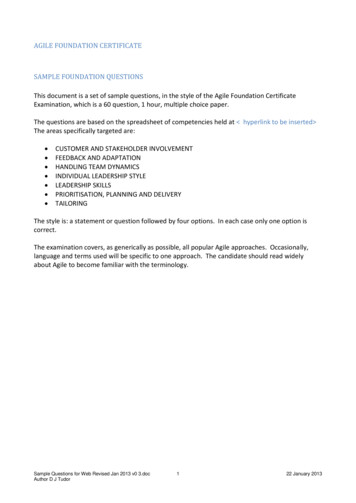
13-113. AN INTRODUCTION TO FOUNDATION ENGINEERING13.1TYPES OF FOUNDATIONSThe foundation is that portion of a structure that transmits the loads from the structure tothe underlying foundation material. There are two major requirements to be satisfied in thedesign of foundations:(a)Provision of an adequate factor of safety against failure of the foundation material.Failure of the foundation material may lead to failure of the foundation and may alsolead to failure of the entire structure.(b)Adequate provision against damage to the structure which may be caused by total ordifferential settlements of the foundations.In order to satisfy these requirements it is necessary to carry out a thorough explorationof the foundation materials together with an investigation of the properties of these materials bymeans of laboratory or field testing. Using these physical properties of the foundation materialsthe foundations may be designed to carry the loads from the structure with an adequate margin ofsafety. In doing this, much use may be made of soil mechanics but to a large extent foundationengineering still remains an art. This chapter will be largely concerned with the contributions thatmay be made by soil mechanics to foundation engineering.There are four major types of foundations which are used to transmit the loads from thestructure to the underlying material. These foundations types are illustrated in Fig. 13.1. Themost common type of foundation is the footing which consists of an enlargement of the base of acolumn or wall so that the pressure transmitted to the foundation material will not cause failure orexcessive settlement. In order to reduce the bearing pressure transmitted to the foundationmaterial the area of the footing may be increased. As the size of the footing increases however,the deeper the effect of footing pressure extends as was illustrated in Geomechanics 1.If the foundation material cannot withstand the pressure transmitted by the footings thepressure may be reduced by combining all of the footings into a single slab or raft covering theentire plan area of the structure as illustrated in Fig. 13.1. Raft foundations are also used to bridgelocalised weak or compressible areas in the foundation material. They are also used where it isdesirable to reduce the differential settlements that may occur between adjacent columns.
13-2FIGURE 13.1 FOUNDATION TYPES
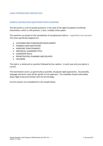
13-3At a building site, firm foundation material may be overlain by strata of weak orcompressible soil. In this case a pile foundation may be a satisfactory solution to transmit thestructural loads through the weak material to the firmer underlying material. The piles may bedriven steel, concrete or timber sections or may be made of cast in place concrete. Thesefoundations are often classified either as end (or point) bearing piles or friction piles dependingupon the major source of the support.Piers are sometimes used for the transmission of large loads to firm foundation materialwhich may be overlain by poorer material. Piers may be considered generally as large diametercast in place piles. Piers are sometimes constructed as caissons in which the foundation membersare sunk through the soil. With open caissons the hole is advanced by means of internal dredgingand in the case of pneumatic caissons excavation is carried out under compressed air to preventthe entry of water and mud into the working chamber.13.2SETTLEMENT ANALYSESFoundations of structures may experience movements through a number of causes,among which may be listed:(a)elastic and inelastic compression of the sub-soil due to the weight of the structure,(b)ground water lowering, producing an increase in effective stress beneath the foundation,(c)vibration due to pile driving, machinery vibrations etc. which is of particular importancein granular soils,(d)seasonal swelling and shrinking of expansive clays,(e)adjacent excavation and construction which may cause movement of the foundations,(f)regional subsidence or movement.This section will be concerned mainly with settlement which is caused by changes inload such as the weight of a building.For conditions of one dimensional compression the calculation of the amount ofsettlement and the rate at which it occurs have been covered in Geomechanics 1. This technique,which is based upon the results of oedometer tests will be referred to as the conventional methodin the following discussion. Unfortunately, in foundation engineering practice, one dimensionalcompression conditions are not frequently encountered and consequently the use of theconventional method for the calculation of the amount and rate of settlement may not be reliable.This is illustrated in Figs. 13.2 and 13.3 which show comparisons between calculated andobserved settlements for the Waterloo Bridge, London, and the Monadnock Block, Chicago. In
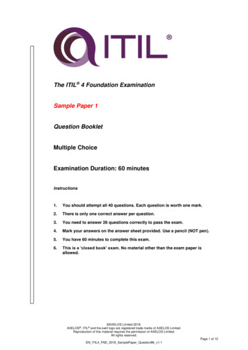
13-4these two instances both the amount and rate of settlement calculated by means of a conventionalmethod considerably underestimate the values observed.In calculating the rate of settlement of a structure it is necessary to determine theboundary conditions in relation to drainage, then to use the appropriate theoretical solution thatsatisfies the actual boundary conditions.Regarding the calculation of the amount of settlement it is widely observed, as illustratedin Figs. 13.2 and 13.3, that a settlement occurs during the period of construction which is notpredicted by the conventional one dimensional method. This type of observation has led to thetwo components of settlement being considered separately. The first component is an immediatesettlement which occurs immediately following the application of load and the second componentis a consolidation settlement which occurs as the pore pressure dissipates. The stress changeswhich take place in the soil as the immediate and consolidation settlements occur are quitedifferent from those when settlement takes place under one dimensional conditions only.The stress path followed by a sample of soil undergoing one dimensional consolidationis illustrated in Fig. 13.4. The stress paths that are drawn in this figure are for a representativeelement of soil beneath a foundation and beneath the water table. Points M and N indicate theinitial effective and total stress points separated by an initial value of pore pressure ui. Followingerection of the structure a vertical stress increase represented by the distance NP will be applied tothe soil. This means that the total stress path will move from point N to point P. If the time ofconstruction is very short in relation to the consolidation time then point M will remain unmoved.This means that the effective stresses will be initially unchanged and the pore pressure in the soilwill increase from the initial value ui to a value represented by the distance MP.As consolidation proceeds the value of the total major principal stress σ1 will remainconstant since it is governed by the externally applied foundation load, and the minor principalstress σ3 will decrease. That is, the total stress path will move from point P to point R. At thesame time the effective stress on the sample will increase as the pore pressure dissipates. Theeffective stress path will move along what is referred to as the Ko line from point M to point Q. AKo line is a locus of the tops of the effective Mohr circles which possess a constant ratio betweenthe minor and major principal stresses. It is along this line that effective stress paths move when asoil is being compressed under one dimensional conditions. Consolidation is complete when theexcess pore pressure has fully dissipated the the pore pressure in the sample returns to the initialvalue.
13-5Fig 13.2 Settlement of Waterloo Bridge, LondonFig 13.3 Settlement of Monadnock Block, Chicago
13-6Fig 13.4 Stress Paths for One Dimensional ConsolidationFig 13.5 Stress Paths for Typical Settlement Situation
13-7For a typical settlement situation in which one dimensional compression conditions arenot present, the stress paths are illustrated in Fig. 13.5. Again, points M and N represent theinitial effective and total stress points which are separated by an initial pore pressure, ui.Following erection of a structure both principal stresses in the soil will change and, in general, thetotal stress path will move along a line represented by NR.Immediately following erection, the effective stress path will move from point M tosome point O. At the same time the pore pressure will increase from the initial value ui to a valuerepresented by the distance OR. In contrast to the one dimensional case the effective stresseschange immediately following the application of the load. In response to this change in stressesthe soil will undergo a settlement known as the immediate settlement.From point O the effective stress path will move horizontally to point Q as the excesspore pressure u dissipates. Consolidation will be complete when the pore pressure in the soilreturns to the initial value. During the movement of the effective stress path from point O topoint Q the consolidation settlement will take place.EXAMPLEA circular pervious footing having a radius of 1.0m is located on the surface of a claystratum 10m thick, which is underlain by a rigid impermeable base. Compare the value of t90 forone dimensional consolidation with the value based upon the more realistic assumption that theconsolidation is three dimensional.one dimensional cv 10-3 cm2/secThe time factors for the one dimensional and three dimensional cases may be taken fromFig. 10.16. Geomechanics 1.One DimensionalT90 0.848 t90 0.848 x 10²sec 10-3 x 10⁻⁴cvt90/H226.9 yrThree DimensionalThe curve corresponding to a (h/a) value of 20 should be used (Fig. 10.16).
13-8T90 2 x 10⁻² cv t90/h2 t90 2 x 10-2 x 102sec10-3 x 10⁻⁴ 0.63 yrThis indicates that the assumption that the consolidation occurs under one dimensionalconditions leads to a significant over estimate of consolidation time.13.3THE SKEMPTON-BJERRUM METHOD OF SETTLEMENT ANALYSISAs discussed in Chapter 9, Geomechanics 1, the settlement which occurs in a soil layerof thickness h when the compression takes place under one dimensional conditions, may beexpressed ashρ ρoed mv σ1dz(13.1)owheremvis the one dimensional compressibility as determined in the oedometer test σ1is the stress change at depth z imposed by the applied load.This one dimensional (oedometer) settlement may be considered as the total finalsettlement provided the loading conditions are strictly one dimensional. As discussed in section13.2, loading conditions are commonly three dimensional, so the final settlement should be reexpressed as follows:ρfinal ρi ρc(13.2)where ρi is the immediate settlement which occurs immediately following the applicationof load, and ρc is the consolidation settlement which occurs as the pore pressure dissipates.Note: A more general expression for the final settlement includes the secondary compressioncomponent ρs which occurs after consolidation is complete. Secondary compression has beendescribed in section 10.7.1. Geomechanics 1. The expression for final settlement would thenreadρfinal ρi ρc ρs
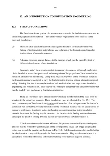
13-9The settlement ρt which occurs at any time t between the time of construction and thecompletion of consolidation is given by the following expressionρt ρi Uρc(13.3)where U is the degree of settlement which was discussed in section 10.6. Geomechanics 1.For the calculation of the immediate settlement (ρi) the use of elastic theory isconsidered to be applicable. The elastic displacement equation which may be used for thiscalculation and which was discussed in section 13.2 Geomechanics 1 is:ρiwhere qB(1 v2 )IρE(13.4)q is the pressure applied by the footing to the foundation materialBis the width or diameter of the footingνIρis the Poisson’s ratio of the soilis the appropriate influence coefficient for settlementEis the relevant value of the Young’s modulus for the soil.For the calculation of the immediate settlement of a saturated fine grained soil therelevant value of the Poisson’s ratio is 0.5. The relevant value of the influence factor Iρ may beobtained from a number of tabulations or figures which are available (for example, see Terzaghi(1943), Fox (1948), Egorov (1958), Scott (1963), Harr (1966), Christian & Carrier (1978), Das(1984)). Influence factors have been evaluated for smooth or rough rigid footings of variousshapes and the centre, corner and average of flexibly loaded areas. Some information oninfluence factors has been provided in Chapter 9 Geomechanics 1 and further data is contained inTable 13.1.For the calculation of the consolidation settlement (ρc) in equations (13.2) and (13.3),Skempton and Bjerrum (1957) proposed the following expressionhρc mv u dz(13.5)owheremvis the one dimensional compressibility of the soilhis the layer thickness uis the pore pressure change developed by the application of load and may bedetermined from equation (7.9) Geomechanics 1 ( u B [ σ3 A ( σ1 - σ3)]).
13-10TABLE 13.1INFLUENCE FACTORS FOR SETTLEMENT OF SMOOTH RIGIDFOOTINGS ON THE SURFACE OF AN ELASTIC SOLID - RIGID BASE AT DEPTH HLength of Footing LWidth of Footing Bρ qBIρ (1-ν2)EVALUES OF IρCircle(DiameterH/BRECTANGLEInfiniteStrip L/B B) L/B 1L/B 2L/B 3L/B 5L/B .5325.00.8180.8731.1551.3091.4751.6191.758 0.8490.9461.3001.5271.8262.246 (after Egorov, 1958)For a saturated soil the pore pressure parameter B is unity so equation (7.9) simplifies to: σ3 u σ1{(A A( σ1 - σ3) σ3(1 - A) )} σ1(13.6)If equation (13.6) is substituted into equation (13.5) the consolidation settlement maythen be expressed as:hρc m σvo1(A σ
may be made by soil mechanics to foundation engineering. There are four major types of foundations which are used to transmit the loads from the structure to the underlying material. These foundations types are illustrated in Fig. 13.1. The most common type of foundation is the footing which consists of an enlargement of the base of a column or wall so that the pressure transmitted to the .File Size: 985KBPage Count: 43