Transcription
Report TVSM-5213ERIK HALLEBRAND and WILHELM JAKOBSSONSTRUCTURAL DESIGN OF HIGH-RISE BUILDINGSSTRUCTURAL DESIGN OFHIGH-RISE BUILDINGSERIK HALLEBRAND and WILHELM JAKOBSSONStructuralMechanics5213HO.indd 1Master’s Dissertation2016-08-08 17:22:53
DEPARTMENT OF CONSTRUCTION SCIENCESDIVISION OF STRUCTURAL MECHANICSISRN LUTVDG/TVSM--16/5213--SE (1-127) ISSN 0281-6679MASTER’S DISSERTATIONSTRUCTURAL DESIGN OFHIGH-RISE BUILDINGSERIK HALLEBRAND and WILHELM JAKOBSSONSupervisors: PETER PERSSON,PhD, Div. of Structural Mechanics, LTHoch JESPER AHLQUIST,MSc, Sweco.Examiner: Professor KENT PERSSON, Div. of Structural Mechanics, LTH.Copyright 2016 Division of Structural Mechanics,Faculty of Engineering LTH, Lund University, Sweden.Printed by Media-Tryck LU, Lund, Sweden, June 2016 (Pl).For information, address:Division of Structural Mechanics,Faculty of Engineering LTH, Lund University, Box 118, SE-221 00 Lund, Sweden.Homepage: www.byggmek.lth.se
AbstractHigh-rise buildings are exposed to both static and dynamic loads. Depending onthe method used and how the structure is modelled in finite element software theresults can vary.Some of the issues and modelling techniques, introduced below, are investigated inthis Master’s thesis. Dynamic effects such as resonance frequencies and accelerationsare considered. The variation in static results from reaction forces, overturningmoments, deflections, critical buckling loads, forces between prefabricated elementsand force distributions between concrete cores are investigated with different models.The models are evaluated by different elements and methods, such as constructionstage analysis, to study the impact these have on the results.Simplified calculations by hand according to different standards, regulations andcodes such as SS-ISO, EKS and Eurocode have been compared with finite elementanalyses. The 3D-finite element software used for the analyses is Midas Gen.From the results it can be observed, when modelling a high-rise building in a finiteelement software, that one model is often not sufficient to cover all different aspects.To see the global behaviour, one model can be used, and when studying the detailedresults another model with a fine mesh, that have converged, is often needed. Thesame principle applies when evaluating horizontal and vertical loads, different modelsor methods are usually needed.Keywords: High-rise buildings, resonance frequencies, accelerations, shear flow, displacements, critical buckling load, finite element.i
AcknowledgementsThis Master’s thesis marks the end of 5 years of study at Lund University. Ithas been completed in association with Sweco AB and the Division of StructuralMechanics at the Department of Construction Sciences at Lund University.We would like to thank Prof. Kent Persson, examiner, for the insight and assistanceof problems encountered in this Master’s thesis. Dr. Peter Persson, supervisorat Lund University, for the support, encouragement and assistance throughout theproject. For providing help with the finite element software Midas Gen as well asuseful knowledge about obstacles encountered, we thank Jesper Ahlquist at SwecoAB.Lund, June 2016iii
ContentsAbstractiAcknowledgements1 Introduction1.1 Background . .1.2 Objectives, aims1.3 Limitations . .1.4 Disposition . .iii. . . . . . . .and method. . . . . . . . . . . . . . .2 High-rise buildings2.1 Stabilisation . . . . . . . . . . . . . .2.2 Concrete buildings . . . . . . . . . .2.2.1 Connections . . . . . . . . . .2.3 Loads . . . . . . . . . . . . . . . . .2.4 Structural systems . . . . . . . . . .2.4.1 Framed tube structures . . . .2.4.2 Bundled tube . . . . . . . . .2.4.3 Tube in tube . . . . . . . . .2.4.4 Diagonalised- and rigid frame2.4.5 Outrigger system . . . . . . .2.4.6 Hybrid structure . . . . . . .2.5 Wind-load effects . . . . . . . . . . .2.6 Comfort requirements . . . . . . . . .2.6.1 SS-ISO 10137 . . . . . . . . .2.6.2 Human response . . . . . . .3 Finite element method3.1 Linear elasticity . . . . . . . . . .3.2 Structural dynamics . . . . . . .3.2.1 Resonance . . . . . . . . .3.3 Difficulties with the finite element3.3.1 Material . . . . . . . . . .3.3.2 Load . . . . . . . . . . . .3.3.3 Discretisation . . . . . . .3.4 Different types of elements . . . .3.4.1 Beam elements . . . . . . . . . . . . . . . . . .method. . . . . . . . . . . . . . . . . . . . v
Contents3.53.4.2 Plate elements . . . . . . . . . . . . . . . . . . . . . . . . . . . 253.4.3 Plane shell element . . . . . . . . . . . . . . . . . . . . . . . . 25Construction stage analysis . . . . . . . . . . . . . . . . . . . . . . . 254 Method4.1 Global critical load - Vianello method . . . . . . . . . . . . .4.2 Wind-load . . . . . . . . . . . . . . . . . . . . . . . . . . . .4.2.1 Static wind-load . . . . . . . . . . . . . . . . . . . . .4.2.2 Dynamic wind-load . . . . . . . . . . . . . . . . . . .4.2.3 Along-wind response . . . . . . . . . . . . . . . . . .4.2.4 Across-wind response . . . . . . . . . . . . . . . . . .4.3 Empirical methods to determine the fundamental frequency4.4 Forces between elements in a prefabricated concrete core . .5 Case study in Midas Gen5.1 Midas Gen elements . . . . . . . .5.2 Description of Göteborg City Gate5.2.1 Geometry . . . . . . . . . .5.2.2 Modelling . . . . . . . . . .5.3 Example case . . . . . . . . . . . .6 Results6.1 Analysis of Göteborg City Gate for vertical and horizontal loads . .6.1.1 Vertical load . . . . . . . . . . . . . . . . . . . . . . . . . . .6.1.2 Horizontal load . . . . . . . . . . . . . . . . . . . . . . . . .6.1.3 Discussion of results . . . . . . . . . . . . . . . . . . . . . .6.2 Analysis of reaction forces . . . . . . . . . . . . . . . . . . . . . . .6.2.1 Discussion of results . . . . . . . . . . . . . . . . . . . . . .6.3 Analysis of overturning moment . . . . . . . . . . . . . . . . . . . .6.3.1 Discussion of results . . . . . . . . . . . . . . . . . . . . . .6.4 Analysis of horizontal deflection . . . . . . . . . . . . . . . . . . . .6.4.1 Discussion of result . . . . . . . . . . . . . . . . . . . . . . .6.5 Analysis of critical load . . . . . . . . . . . . . . . . . . . . . . . . .6.5.1 Discussion of result . . . . . . . . . . . . . . . . . . . . . . .6.6 Analysis of resonance frequencies . . . . . . . . . . . . . . . . . . .6.6.1 Discussion of result . . . . . . . . . . . . . . . . . . . . . . .6.7 Analysis of acceleration . . . . . . . . . . . . . . . . . . . . . . . . .6.7.1 Along-wind acceleration . . . . . . . . . . . . . . . . . . . .6.7.2 Across-wind acceleration . . . . . . . . . . . . . . . . . . . .6.7.3 Discussion of results . . . . . . . . . . . . . . . . . . . . . .6.8 Analysis of forces between elements in a prefabricated concrete core6.8.1 Discussion of results . . . . . . . . . . . . . . . . . . . . . .6.9 Vertical displacement . . . . . . . . . . . . . . . . . . . . . . . . . .6.9.1 Vertical displacement in column . . . . . . . . . . . . . . . .6.9.2 Discussion of results . . . . . . . . . . . . . . . . . . . . . .7 Conclusions and further 596063646565656666676869696972727278787985
ContentsBibliography87AppendicesIA Drawings of Göteborg City GateIB Static wind-load - Strictly according to ECC Static wind-load with no cs factorD Static wind-load with τ factorE Wind-load according to EKS10XIXIIIXVXVIIF Dynamic wind-loadXIXG DeflectionXXIH Vianello methodIBuckling and P-delta analyses in MidasJ Fundamental frequency according to Stafford Smith & CoullK Calculations of accelerationL Calculation of shear-flow in a C-beamXXVIIXXIXXXXIXXXIIIXXXVIIvii
1 Introduction1.1BackgroundThe process of designing high-rise buildings have changed over the past years. Inthe most recent years it is not unusual to model full three-dimensional finite elementmodels of the buildings. This due to the increased computational power and moreadvanced software. However, these models produce huge amount of data and resultswhere possible errors are easily overlooked, especially if the model is big and complex.If the engineer is not careful and have a lack of knowledge of structural behaviour andfinite element modelling, it is easy to just accept the results without critical thoughts.Furthermore, different ways of modelling have a big influence on the force and stressdistribution. This can lead to time consuming discussion and disagreements betweenengineers as they often have different results from calculations on the same building.Sweco AB were interested in initiating a Master’s thesis that investigated differentways of modelling and how they affect the outcome. The Division of StructuralMechanics at Lund University were interested in a similar Master’s thesis were thedynamics of high-rise buildings were to be analysed. Furthermore, investigations ofhow well analytical calculations by hand according to standards, codes and regulations of accelerations and resonance frequencies correspond to the results of largefinite element models were to be conducted.1.2Objectives, aims and methodThe objectives of this Master’s thesis are to analyse different methods, codes andguidelines used when performing calculations on high-rise buildings in regards todeflections, resonance frequencies, accelerations and stability. The results from thesemethods are then compared with results from finite element models in order toevaluate differences and verify the methods and models.The aims of the thesis are to provide insight on how different ways of modellingbuildings in finite element programs affect the results. This is especially investigatedwhen comparing vertical and horizontal loading with different modelling techniquesand how the shear flow can be determined with a model using plate elements in amesh compared to calculating it from the shear force in a model with wall elements.Furthermore, the accuracy of analytical calculations made by hand in comparison1
1. Introductionto large finite element calculations are established. This to provide a helpful tool indiscussions between engineers as well as provide basis for future research.A comprehensive literature study has been made in the area of high-rise buildingsregarding the history, design process, code regulations, finite element modelling aswell as static and dynamic response. This translated into a case study of a highrise building on which analytical calculations of deflection, critical buckling load,resonance frequencies and shear flow were made. The analytical calculations havethen been compared to finite element calculations in Midas Gen. Furthermore, ananalysis of accelerations and overturning moment from wind-load were made andcompared to the comfort requirements.1.3LimitationsAnalyses of high-rise buildings consists of many stages and factors and to evaluateall of these are beyond the scope of the Master’s thesis. For concrete, no effectsfrom creep, shrinkage or temperature effects have been analysed. The concrete havealso been considered uncracked. Furthermore, no design of element cross-sectionshave been made and the accelerations of the building are calculated according toEurocode, hence, no time-history analysis is performed.1.42DispositionChapter 1Gives an introduction to the subject and problem as well as thelimitations that have been made.Chapter 2Presents the fact gathered from the literature study and containshistory as well as commonly used design methods for high-risebuildings.Chapter 3Theory regarding the basis of the finite element method as well asdifferent software applications are presented in this chapter.Chapter 4Describes the chosen methods used for calculations on thebuilding.Chapter 5The case study and the different types of models used for analysisare presented in this chapter.Chapter 6Shows the results from the analysis made and some discussion ofthe results.Chapter 7Contains the conclusion drawn from the results as well asinformation about further studies on structural design of high-risebuildings.
2 High-rise buildingsA building is defined as high-rise when it is considerably higher than the surroundingbuildings or its proportion is slender enough to give the appearance of a tall building[14]. The construction of high-rise buildings started at the end of the 19th centuryin Chicago, with the evolution shown in Figure 2.1. This was made possible becauseof new inventions such as the safe elevator in 1853 [27] and the telephone in 1876[5], that enabled transport of building materials and the ability to communicate tohigher levels. In addition, the building materials changed as they went from woodand masonry to using steel frames with lighter masonry walls. Earlier buildingsthat were built with heavy masonry walls was limited to certain heights by its ownself-weight. With steel frames the masonry could be thinner and act only as facadefor weather protection and taller buildings could be constructed [19].During the industrial revolution in Europe the need for warehouses, factories andmulti-storey buildings were huge. Europe also played a major role in developingnew materials such as glass, reinforced concrete and steel. Before 1945 the high-risebuildings in Europe were few and below the 100 meter limit and it was not untilafter the Second World War the construction of high-rise buildings excelled. Thishad to do with the reconstruction of all destroyed cities and the expanded demandfor offices and residential [16].In Sweden during the early 20th century there was a continued housing shortage andlow housing conditions [26]. It was not until 1960 when the construction of newresidencies skyrocketed. The politicians decided to build 100 000 new residenciesa year for 10 years. This is known as the million-program. To be able to meetthe requirements of the increased production the construction with prefabricatedelements increased. In addition to faster production was that the decreased costwould give lower cost for living. During the time 1963–69 the production of prefabricated buildings was increased six fold. 20% of all residences built during thetime was prefabricated and four major principles for building with prefabricatedconcrete elements were used [26] which are shown in Figure 2.2. In the 1970s themillion-program was aborted due to the recession and oil-crisis which led to a drasticdecrease in the production of new residencies [26]. The production dropped to only30 000 residencies in 1986. In the end of the 1980s the production rose again toabout 60 000 residences a year. The tallest building in Sweden today is TurningTorso in Malmö with its 190 meter and 54 stories above ground [20]. Turning Torsois an in-situ cast concrete building with the facade rotating 90 degrees from topto bottom. When constructing with precast concrete the height of the buildings is3
2. High-rise buildingsFigure 2.1: Diagram of buildings that have once claimed the title ‘World’shighest building’ [18].usually much lower than buildings cast in-situ cast. The tallest building ever madewith precast concrete is The Breaker Tower in Seef, Bahrain. The building reachesjust above 150 meter and has 35 stories [11]. Comparing this with the tallest in-situcast concrete building which is Burj Khalifa in Dubai, United Arab Emirates, seeFigure 2.1, reaching 828 meters and has 163 stories [13]. High-rise buildings doesnot only give more residencies on smaller area but is also a landmark for the city orcountry and represents power.2.1StabilisationThe buildings behaviour when excited to horizontal wind-load is described in thissection, for more detailed information see [16].Knowledge, technology and construction materials are constantly evolving and so isthe strife for constructing higher buildings. However, it does not go without somechallenges and issues. First off, the vertical loads increases with the height of thebuilding. There is also the large effect from horizontal wind-load on the building.The buildings behaviour under the lateral loading can be seen as a cantilever fixed atthe ground. If the wind is assumed to have a uniform distribution the base-momentincreases quadratic with the height. However, the real shape of the wind pressureis increasing with the height, which gives even greater base-moment, see Figure 2.3.One of the main tasks when designing high-rise buildings is its ability to absorb thehorizontal forces and to transmit the resulting moment into the foundation. Oneway to effectively achieve this are coupled load-bearing vertical walls. However,this will lead to tensile stresses in the concrete walls on the loaded side. In orderto minimise these stresses, self-weight of slabs etc. are placed on the walls to getcompressive stresses. Other ways of dealing with horizontal loading are presentedmore in detail in Section 2.4.The higher a building is, the more important it is to consider the choice of cross4
2. High-rise buildings(b) Load-bearing perimeter(a) Load-bearing cross walls.walls.(c) Concrete core with angular(d) Concrete core with volumeelements.elements.Figure 2.2: Four major principles of prefabricated construction [1].sections, materials and structural systems as well as the demands on functionality.Factors that needs to be considered are deflections and accelerations from horizontal loading that mainly occurs from unexpected deflections, wind or earthquakes.Unexpected deflections may arise when imperfections in the elements occur duringthe manufacturing or if the foundation is uneven due to an inhomogeneous site.Any unexpected deflection causes additional lateral forces and must be considered.Horizontal loading from wind may also cause sway in the building. This since highrise buildings are susceptible for oscillation. The wind should therefore not only beseen as a static load but also as a dynamic load. To determine how the building respond to wind-loads, wind tunnel experiments are often performed. The oscillationaffects the building in several ways, how the people inside perceives the sway andthe maximum horizontal deflection that arises.5
2. High-rise buildingsFigure 2.3: Wind-load, moment and stiffness diagram for a high-rise building [16].2.2Concrete buildingsIn this section some differences between cast in-situ and precast concrete are explained as well as different types of connections, for more detailed information see [7].Concrete buildings can either be cast in-situ, composed with precast elements ora combination of both. If the building is cast in-situ it is possible to start theactivities on site in an early stage. Preparation for scaffolding and moulding canstart as soon as the contract is assigned to the contractor and the design of thebuilding starts. This is not possible when constructing with precast elements asall decisions regarding dimensions, shapes and so forth has to be taken long beforethe activities on site can start. When using precast elements it is of importance toindustrialise the manufacturing. This implies manufacturing in covered factories,use of automatic tools and thoroughly plan the production process. There are someimportant differences regarding cast in-situ and precast buildings. When a buildingis cast in-situ the elements are created in moulds on site and are constantly checkedto have the correct height. But when a building is constructed with precast elementsthe elements are created in a factory where the factory worker is fully dependenton the drawing. If for example a column have the wrong height on the drawing, noone will correct this in the factory and an incorrect column will be created causingproblems on site.2.2.1ConnectionsWhen designing a precast building it is important to consider the connections between elements, which are part of the assembly procedure and should not interfere.Connections can be divided in wet and dry connections. The difference betweenthese are the use of concrete or mortar. Wet connections are for example, mortarjoints, cast in-situ blocks or cast in-situ slabs that are more fire resistant, less sensitive for tolerance criteria and more ductile than dry connections. Examples of dryconnections are free supports, welded connections and cold joints which are quickto assemble.6
2. High-rise buildings2.3LoadsLoads that has to be taken into consideration when designing a building are verticalloads from self-weight, imposed loads, snow loads and horizontal loads from bothwind and unintended inclinations. For tall buildings, as earlier mentioned, thehorizontal loading from wind is usually the design load. The vertical loads are theself-weights, finishing loads and live loads and they are transferred to the foundationthrough columns, load-bearing walls or towers. The live load depends on the typeof usage in the building and on the standard used for designing [16]. In Eurocode[30], the live load varies from 0.5–5.0 kN/m2 . The higher value is often used foroffices to take the variable partitioning and the greater live load in corridor areasinto account [16]. Some reduction of the live load can be made depending on thenumber of stories, but may never exceed 40% for any construction element [16].The horizontal load from wind working as a distributed load on the facade, whichtransfers the load to the slabs. The slabs are working as diaphragms and providesthe lateral transfer of the shear load to the vertical elements and also as a stabilityunit for the compression flange of the steel beam beneath [36]. The shear forces inthe diaphragms occur mainly in the concrete because of its in-plane stiffness. Thehorizontal loads are transferred from the slabs to the beams through welded studs.Depending on how the slabs are connected to the facade, the stress distributions inthe slabs will vary. For example, the slabs can be connected directly to the facade,which gives a distributed load. The facade can also be connected to columns whichwill provide point loads instead. The load distribution depends on the stiffness ofthe elements as stiffer units attract more load than weaker.When designing vertical walls in a building both shear and bending deformation mayoccur. For low robust walls the bending is negligible and for tall slender structuresshear is negligible. Considering the entire building the shear wall becomes tall andslender, however, the walls in each plane are low and robust making it susceptibleto both shear and bending. For a tall building the deformation shapes from bendingand shear can be seen in Figure 2.4.2.4Structural systemsA building needs to be stabilised for horizontal load and to achieve this, severaldifferent structural systems can be chosen. Some of these are shown in Figure 2.5and described in this section, for more detailed information see [34]. All of thedifferent systems have evolved from the traditional rigidly jointed structural frame.The fundamental design for all these structural systems have been to place as muchof the load-carrying material as possible around the buildings external fringe tomaximise its flexural rigidity. For all structural systems, advantage can be takenby locating the main vertical members and, with the compressive stresses from selfweight, suppress the lateral load tensile stresses. This to avoid net tension in thevertical members and uplift in the foundations. For some structural systems it isnecessary to have self-weight at the outer vertical members in order to achieve this.7
2. High-rise buildingsFigure 2.4: Deformation shapes of a tall building. a) Bending deflection, b)Shear deflection and c) Total deflection [34].Figure 2.5: Different structural systems, where A) represents a framed tubesystem, B) a bundled tube system, C) a tube in tube system, D) a diagonalisedsystem, E) a core and outrigger system and F) a hybrid system [15].In the following sections, explanation are given of the structural systems shown inFigure 2.5.2.4.1Framed tube structuresFor framed tube structures the lateral resistance is given by very stiff moment resisting frames that form a tube around the perimeter of the building. The framesconsists of closely spaced columns, 2–4 meters between centres, connected by girders.The tube carries all the lateral load and the self-weight is distributed between theouter tube and the interior columns or walls. For the lateral loading the perimeterframes aligned in the load direction acts as webs of the tube cantilever and thoseperpendicular to the load direction acts as flanges. The tube structure is suitablefor both steel and reinforced concrete buildings and have been used in the range of40–100 stories. Framed tube systems have been the most significant modern development in high-rise structural forms and is easily constructed and usable for greatheights. For the aesthetics of the tube structure the enthusiasm is mixed, some likethe logic of the clearly expressed structure while others criticise the grid-like facadeas small windowed and repetitious. A disadvantage with the tube structure is theefficiency for the flange frames, for lateral loading, which tend to suffer from shearlag with the result that the mid columns are less stressed than the corner columnsand therefore not contributing as much as they could.8
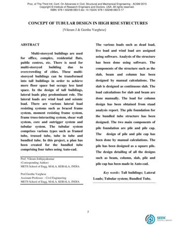
2. High-rise buildingsFigure 2.6: Bundled tube intersection [25].2.4.2Bundled tubeThe bundled tube structure consists of four parallel rigid frames in each orthogonaldirection, interconnected to form nine bundled tubes, see Figure 2.6. The principleis the same as for the single tube structure where the frames in the horizontal loaddirection acts as webs and the perpendicular frames acts as flanges. By introducingthe internal webs the shear lag is drastically reduced and as a result the stressesin the columns are more evenly distributed and their contribution to the lateralstiffness is more significant. This allows for the columns to be spaced further apartand to be less striking.2.4.3Tube in tubeWhat differentiates the tube in tube concept from other structural systems is thatan outer framed tube (hull), is working together with an internal tube (core), usually elevator shafts and stairs, to resist both the lateral and vertical loading, seeFigure 2.7. This provides increased lateral stiffness and can be seen as the shearand flexural components of a wall-frame structure.2.4.4Diagonalised- and rigid frameIn braced frames the lateral resistance is given by diagonal members that, togetherwith the girders, form a web of vertical trusses, where the columns acting as chords,see Figure 2.8. Bracing systems are highly efficient of resisting lateral loads. Thisdue to the horizontal shear in the building is resisted by the horizontal componentsresulting in tensile and compressive actions in the web members. The bracing systemis an almost steel exclusive system since the diagonals are inevitably subjected totension for one or the other direction of the lateral loading. Braced systems areable to produce a very stiff lateral structure for a minimum of additional materialwhich makes it economically efficient for any height. The major disadvantage withdiagonal bracing is that it is limiting the internal planning and the location ofwindows. Furthermore, the connections to the diagonals are expensive to fabricateand erect.9
2. High-rise buildingsFigure 2.7: Tube in tube [2].In rigid frame structures the columns and girders are joined together by momentresistant connections. The lateral stiffness of a rigid frame depends on the bendingstiffness of the columns, girders and connections in-plane. This type of structureis ideally suited for reinforced concrete buildings because of the stiffness from reinforced concrete joints. For steel, these connections can be made although they areexpensive. An advantage with rigid frame structures is the possibility of planningand fitting of windows because of the open rectangular arrangement. A disadvantageis that the self-weight is resisted by the action from rigid frames. Negative momentsare induced in girders adjacent to columns causing the mid-span positive momentsto be significantly less than in a simply supported span. For buildings where selfweights dictate the design, usually below 10 stories, economics in member sizes thatarise from this effect tend to be offset by the increased cost of the rigid joints.2.4.5Outrigger systemThe outrigger system is an efficient structural form that consists of a central corewith outriggers, connecting the core to the outer columns. The central core containsof either braced frames or shear walls. When the building is loaded laterally the vertical plane rotations are resisted by the outriggers through tension in the windwardcolumns and compression in the leeward columns, see Figure 2.9. This is augmenting the lateral stiffness of the building and reducing the lateral deflections as wellas the moments in the core. In addition, the outriggers join the columns and makesthe building behave almost as a composite cantilever. Even the perimeter columns,those not directly connected to the outriggers, can be used to increase the lateralresistance of the building by connecting all the perimeter columns with a horizontalgirder around the building’s facade. Multilevel outrigger systems can provide up tofive times the moment resistance of a si
structural design of high-rise buildings erik hallebrand and wilhelm jakobsson structural design of high-rise buildings 55213ho.indd 1213ho.indd 1 22016-08-08 17:22:53016-08-08 17:22:53. department