Transcription
RISAConnectionRapid Interactive Structural Analysis for ConnectionsVersion 12.0 - General ReferenceRISA Tech, Inc.26632 Towne Centre Drive, Suite 210Foothill Ranch, California 92610(949) 951-5815(949) 951-5848 (FAX)risa.com
Copyright 2020 RISA Tech, Inc. All Rights Reserved. RISA is part of the NemetschekGroup. No portion of the contents of this publication may be reproduced or transmitted inany means without the express written permission of RISA Tech, Inc. RISA and the RISAlogo are registered trademarks of RISA Tech, Inc.We have done our best to ensure that the material found in this publication is both usefuland accurate. However, please be aware that errors may exist in this publication, and thatRISA Tech, Inc. makes no guarantees concerning accuracy of the information found here orin the use to which it may be put.
Table of ContentsTable of ContentsBefore You Begin1Available Connections40Overview1System Requirements1Member Information41Program Limits1Design Checks41License Agreement2Design Checks for Canadian Code42Technical Support2Connection Design Procedures4233Column Stiffener Checks for Moment Connections444HSS Checks per the CIDECT Manual45Menus and Toolbars4Canadian Code Limitations46Shortcut Keys8Connection View8Available Connection TypesAvailable Connection TypesApplication InterfaceResultsStability and Geometry Checks4147Erection Stability47Project Explorer10Rotational Ductility47Connection Properties11Bolt Geometry Restrictions49Units19Stabilizer Plates50Sign Convention20Axial Load22Shear Yield Strength52Beam Shear23Shear Rupture Strength52Beam Moment23Plate Tension Yield52Story Shear23Tension Rupture53Graphic Display24Beam Flexural Rupture543D View Controls24Beam Tension Rupture552D View Controls25Block Shear Strength55Reports View26Plate Tearout56Plot Options27Plate Flexural Yielding5829Plate Flexural Rupture5929Plate Compression Buckling5932Shear Tab Interaction Checks60Description32Plate Flexural Buckling62Solution33Angle Leg Bending6238Bearing Limitation63Customizing RISAConnectionPreferences(Global) Project SettingsConnection Modeling ProcessCreating a Project38Creating a Connection39General Reference ManualMaterial ChecksBolt Checks5264Bolt Material Options64Bolt Group Eccentricity64I
Table of ContentsSlip Critical Considerations66Bolt Shear Strength67Bolt Tensile Strength68Bolt Bearing Strength75Weld Calculations78Weld Geometry78Base Material Strength79Elastic Weld Strength80ICR Weld Strength83Non-Eccentric Fillet Weld Strength84PJP Weld Strength86CJP Weld Strength87Weld Limitations87Double-Sided Connections89Defining the Connection89Limit States91Results Report94Skewed Connections96Geometry Input and Considerations96Loading Considerations99Design Considerations100Coped Beam Checks105Calculation of Snet (Net Section Modulus) 105Flexural Rupture Strength105Local Web Buckling Strength106Lateral Torsional Buckling Strength107Limitations108Column Connection ChecksII109Force Distribution109Column Flange Bending (Shear Connections)111Column Web Flexural Yielding (Shear Connections to Column Web)116Column Web Yielding (Shear Connectionsto Column Flange)117Column Web Yielding (Moment Connections to Column Flange)118Column Web Crippling (Shear Connections)119Column Web Crippling (Moment Connections)120Column Web Buckling (Moment Connections)121Column Panel Zone Shear122Column Web Out of Plane Checks123Design Checks for HSS Members126HSS Limitations126CSA HSS Limitations127HSS Punching Shear127Shear Tab127Clip Angle, End Plate128Shear Tab128Clip Angle, End Plate129Shear Tab129Clip Angle, HSS T-Connection130Through-Plate Welds130HSS Transverse Plastification130Shear Tab131Clip Angle, End Plate132Shear Tab132Clip Angle, HSS T-Connection133HSS Flexural Plastification134Shear Tab134Clip Angle, End Plate135Column Flange Bending (Moment Connections)112Shear Tab135Column Flexural Yielding112Clip Angle, HSS T-Connection136Column Web Punching Shear (Shear Connections)115HSS Sidewall Local Axial Yielding137Clip Angle, HSS T-Connection137Column Web Axial Yielding (Shear Connections to Column Web)115HSS Sidewall Local Flexural Yielding138RISAConnection v12.0
Table of ContentsClip Angle, End Plate138Clip Angle, HSS T-Connection138Limitations170Branch Axial Yield139Diagonal Brace Connection174HSS T-Connection139Chevron Brace Connection179Branch Flexural Yield140Knee Brace (Kicker Brace) Connection181HSS T-Connection140Gusset Plate Design182HSS Combined Interaction140Welds to Face of HSS141Wide Flange Brace Members with ClipAngle Gusset Connections185Connection Eccentricity187Knife Plate or End Tee Unbraced Lengths 141Column Stress Interaction Parameter, Qf141Column Buckling Reduction Factor, χ142Design Checks for Moment Connections143Vertical Brace ConnectionsSeismic Vertical Brace Connections170188How to Create a Seismic Vertical BraceConnection188Seismic Input Values191Limitations- Seismic Vertical Braces192Seismic Brace Design Force Calculations192OCBF Connection Strength197SCBF Connection Strength197Additional Considerations of SeismicBrace Force Distribution198154Seismic Vertical Brace Checks201Transverse Stiffeners154Seismic Detailing DXF Output204Doubler Plates155Required Flange Force143End Plate Moment Checks143Axial Force in Moment Connections149Moment Connections with Column Stiffeners149Moment Connections into a Column Web(Weak Axis)150Stiffener Checks for Moment ConnectionsBase Plate Connections205How to Create a Base Plate Connection205Limitations- Base Plate Connections207Input Properties207Seismic Moment Connection Input Values 162Design Methodology215Seismic Moment Connection Limitations162Base Plate Design Checks216Reduced Beam Section (RBS) MomentConnection162Additional Brace to Base Plate DesignChecks223Seismic Moment ConnectionsHow to Create a Seismic Moment Connection158158Welded Un-reinforced Flange Welded Web(WUF-W) Moment Connection164Bolted Stiffened/Un-stiffened ExtendedEnd Plate (BEEP) Moment Connection165Bolted Flange Plate (BFP) Moment Connection165Ordinary Moment Frame (OMF) Connections165Seismic Moment Connection Checks166RISAFloor and RISA-3D Integration224Connection Grouping224Grouping Behavior225Loading/Load Combinations230Solving Connections231Viewing Results (in RISAConnection)232Viewing Results (in RISAFloor or RISA3D)233Seismic Moment Connection DXF Output 169General Reference ManualIII
Table of ContentsRound-tripping between RISAFloor/RISA3D and RISAConnection234MiscellaneousHilti PROFIS Integration236237Exporting to Hilti PROFIS237Importing Hilti PROFIS Results240Currently Supported Connections243Limitations243Changing Hilti PROFIS Accounts243Troubleshooting244Tekla Structures Integration245Connection Grouping245Grouping Behavior246Loading248Solving Connections250Viewing Results (in RISAConnection)250Viewing Results (in Tekla Structures)252Round-tripping between Tekla Structuresand RISAConnection253Tekla Structures Integration Procedure2541. Completing the Tekla Structures Model 2542. Sending the Model to RISAConnection 2543. Configuring Connections and Solving inRISAConnection2544. Connection Results Viewing in Tekla254Workflow Diagrams255DXF ExportExporting DXF FilesPrinting257259Print Current View259Report Creation Wizard259Technical SupportIV257262RISAConnection v12.0
Before You BeginBefore You BeginWelcome to the RISAConnection General Reference manual. Please read this topic prior to installing the programand pay particular attention to the License Agreement. If you are a first time user of RISAConnection it would bebeneficial to browse through this manual to become familiar with the interface and connection design capabilities.OverviewRISAConnection is a hot-rolled steel connection design program that allows you to design many types of connections for different hot rolled steel shapes and configurations. The program utilizes multiple graphical viewswith a tabular input location to make connection modeling straightforward and efficient. After configuring yourconnection, the program will give detailed calculations for all of the different connection failure modes completewith full calculation values that you can verify quickly and easily.System RequirementsOne of the following operating systems is required:llMicrosoft Windows 10 (64 bit only)Microsoft Windows 8.1 (64 bit only)SoftwareThe following additional software is required:lMicrosoft .NET Framework 4.5 or laterInternet (Subscription License Only)An internet connection is required to launch the program. The internet connection must be maintained as long asthe program is open, although brief internet outages (a few minutes) do not affect the user's ability to keep theprogram open.HardwareThe following hardware is required:lllll1 GHz or faster processor (x86-64)1024x768 or higher monitor resolution2 (or more) button mouse, mouse wheel recommended1 GB of RAM4 GB of hard disk spaceProgram LimitsHardware LimitationslRISAConnection is not a multi-threaded application, which means that it runs entirely within a single processor core. Therefore the program does not take full advantage of multi-core or multi-processormachines. This limitation affects how long it takes to solve a group or project with multiple load combinations on models integrated with RISA-3D/RISAFloor.General Reference Manual1
Before You BeginDemonstration Version LimitationsWhile you can open and solve any model, you cannot save any project or connection. Also the following limitations apply:lllllYield and rupture capacities for all steel materials are hard-coded as Fy 25 ski and Fu 40 ksi.The welds are hard-coded to have a strength of 50 ksi.The allowable compressive stress of concrete for base plate connections is always set to f'c 1,500 psi.RISA-3D and RISAFloor models may export connections into the Demo version of RISAConnection but theother limitations (above) will still apply.The Demonstration Version will automatically shut down if left open for 24 continuous hours.License AgreementFor the full license agreement, please visit: risa.com/eulaTechnical SupportComplete program support is available to registered owners of RISAConnection and is included in the purchaseprice. This support is provided for the life of the program. The "life of the program" is defined as the time periodfor which that version of the program is the current version. In other words. whenever a new version of RISAConnection is released, the life of the previous version is considered to be ended. Technical support is a limitedresource; first priority will always be given to those clients who are current.See Technical Support for a list of your support options.2RISAConnection v12.0
Available Connection TypesAvailable Connection TypesThe following connection types are available for design in RISAConnection.Available Connection TypeslllllllllllBeam to Column Shear Connections (shear tab, clip angle, end plate).o Columns may be Wide Flanges, HSS tubes, or HSS pipes (shear tab only).o Beams may be Wide Flanges or Channels (not for end plate).o Double-sided connections available for clip angle shear connections into the column web.o Skewed connections available for Wide Flange or HSS tube columns (shear tab only)Beam to Girder Shear Connections (shear tab, clip angle, end plate).o Girders may only be Wide Flanges.o Beams may be Wide Flanges or Channels (not for end plate).o Double-sided connections available for clip angle shear connections into the girder web.o Skewed connections available for shear tabs only.Shear Splices (beam and column).o Columns may only be Wide Flanges.o Beams may only be Wide Flanges.Beam to Column Flange Moment Connections (direct weld, extended end plate, flange plates, flush endplate).o Direct Weld and Flange Plate moment connection columns may be Wide Flanges or HSS Rectangular Tubes.o Extended End Plate and Flush Plate moment connection columns may only be Wide Flanges.o Beams may only be Wide Flanges.Beam to Column Web Moment Connections (direct weld, flange plates).o Columns may only be Wide Flanges.o Beam may only be Wide Flanges.Moment Splices (beam and column, direct weld, end plate, flange plate).o Columns may only be Wide Flanges.o Beams may only be Wide Flanges.Vertical Brace Connections (Chevron, Diagonal Brace, and Knee Brace).o Columns may be Wide Flanges, HSS Tubes, or HSS Pipes.o Beams may be Wide Flanges, HSS Tubes (Chevron and Knee Brace connections only), or HSS Pipes(Chevron and Knee Brace connections only).o Chevron and Diagonal Braces may be Wide Flanges, HSS Tubes, HSS Pipes, Channels, WTs, DoubleAngles, or Single Angles.o Knee Braces may be HSS Tubes, HSS Pipes, Channels, WTs, Double Angles, or Single Angles.Single Column Base Plate Connections.o Column may be a Wide Flange, Tube, or Pipe.Brace to Base Plate Connections.o Column may be a Wide Flange, Tube, or Pipe.Brace to Column Base Plate Connections.o Column may be a Wide Flange, Tube, or Pipe.o Brace may be HSS Tube, HSS Pipe, Single Angle, Double Angle, WTs, or Channels.Truss HSS T-Connections.o Chord member must be a HSS Tube.o Branch member must be a HSS Tube.General Reference Manual3
Application InterfaceApplication InterfaceModeling features in RISAConnection may be accessed through the ribbon toolbar, shortcut keystrokes, and theConnection Properties spreadsheet. You may use any or all of these options to interact with the software. Theribbon toolbar contains the tools required to create new models, save, print, access Global Project Settings, andthe viewing options. The shortcut keys provide a fast way to access features should you use the program oftenenough to make them familiar to you. Finally, the Connection Properties spreadsheet contains all the user-inputdata to model your connection. These features are discussed in the sections below.Menus and ToolbarsTitle BarThe bar at the top is called the title bar. The title of your project can be seen in the center of the bar, and thebuttons are described below:ButtonFunctionStarts a new projectOpens a previously created projectAdds a connection to the current projectSaves the current projectPrints the current connection viewAccess the report printing optionsUndo previous changesRedo previous changesMinimize program windowMaximize program windowRestore down the program windowClose the programRibbon ToolbarJust beneath the title bar is the ribbon toolbar. This toolbar is divided into tabs to combine similar features andtools. Each tab is described below.4RISAConnection v12.0
Application InterfaceFile MenuThe File menu contains the same model options as the Title bar (New, Open, Save, Print) with a few more. Theadditional functions are described below.General Reference Manual5
Application InterfacellllllllSave As - Allows you to save the previously saved model with a new name, or into a new location.Append - Use this feature to combine two models into one. Open the first model, then go to File - Appendand select the second model. The two will be merged into one model file. Be sure to rename in order topreserve the original single files!Export - RISAConnection has three export options:o Export to RISA-3D: If you have a RISA-3D/RISAConnection integrated model, you can use thisoption to send your RISAConnection results back to the RISA-3D model.o Export to DXF - Single Connection: Export the detail drawings of the currently selected connection to a DXF file.o Export to DXF - All Connections: Export the detail drawings of all connections in the project to aDXF file.Page Setup - Access to printing page setup options.Application Settings (Preferences) - This menu contains global solution and display options which applyto all connections in the project. From this menu, you can adjust the numerical preferences, start-upoptions, and the company logo to include on your printed report. See Customizing RISAConnection formore information.Help - Access to the following information:lThe RISAConnection Manual.lThe list of Available Connection types.lThe Check for Updates feature.lThe About RISAConnection program and licensing information.Exit - Closes the program.Recent Projects - Lists the models that you have recently created / edited with RISAConnection.Home MenuThe Home menu contains some global buttons which effect the whole project and some buttons which are onlyapplicable to whichever view you are in. For example, when you are in the 3D View, the Home menu will containoptions for the view angle of the connection, and when you are in the 2D View, the options for toggling the dimensions and bolts become available.The buttons are described below:Button6Function3DView2DViewReportsAdd a new connection to the project.xxxCopy the selected connection.xxxSave connection geometry and input as thenew default for all future connections.xxxRISAConnection v12.0
Application InterfaceButtonGeneral Reference ManualFunction3DView2DViewReportsDelete the selected connection.xxxAccess the Units dialog.xxxAccess the Global Parameters.xxxExport the connection results to RISA-3D orRISAFloor (for integrated models only).xxxExport the connection results to Tekla Structures (for integrated models only).xxxAccess connection display options. SeeGraphic Display for more information.xxxToggle an opaque or transparent view.xToggle the view of the bolts on or off.xToggle the view of the dimensions on or off.xToggle the view of the Whitmore Section andunbraced length (applicable to vertical bracedconnections only)xSnap to isometric view.xSnap to top view.xSnap to right view.x7
Application InterfaceButtonFunction3DView2DViewReportsSnap to front view.xSnap to left view.xCopy the top gusset geometry to the bottomgusset (for Vertical Brace Diagonal Connections only).xxxCopy the bottom gusset geometry to the topgusset (for Vertical Brace Diagonal Connections only).xxxSolve all connections in the project (for integrated models only).xxxSolve all connections in the group (for integrated models only).xxxSolve just the selected connection (for integrated models only).xxxThis button allows you to access the HTML5help menu, check for updates, and view theAbout Connection page which contains version and licensing information.xxxShortcut KeysThe following keys (or key combinations) can be accessed as shortcuts to help speed up your modeling.Shortcut KeyActionCRTL OOpen a FileCRTL SSave a FileF1Access Help MenuF2Switch to a 2D ViewF3Switch to a 3D ViewConnection ViewThe Connection View provides options for viewing both the graphical display of the connection (in 2D or 3Dview) and also viewing the result output report.8RISAConnection v12.0
Application InterfaceGraphical DisplayResults ReportGeneral Reference Manual9
Application Interface3D ViewThis view allows you to move your connection around and view it from all sides and angles. If you click on a specific connection element in this view it will highlight in the Connection Properties section. See the Graphic Display topic for more information.2D ViewViewing the model in 2D allows you to see each of the components of the connection, complete with dimensions,bolt holes and some assembly views.If you click on a specific connection element or dimension, that element or dimension will highlight in the Connection Properties section. See the Graphic Display topic for more information.ReportsThe Reports section shows all the results from the program, including component properties and design checks.See the Graphic Display topic and the design checks topics for more information.Project ExplorerThe Project Explorer shows the current project along with a list of all the connections in the project file.10RISAConnection v12.0
Application InterfaceConnection PropertiesThe Connection Properties gives ability to define all of the parameters for the connection. Modifying this dataautomatically updates the design check calculations in standalone mode. If integrated with RISAFloor and/orRISA-3D, then you must re-solve the connection after changes.General Reference Manual11
Application InterfaceNote:lIf using RISAConnection integration with RISAFloor and/or RISA-3D, some of these fields are grayed out incertain scenarios. For more information on this see the RISAFloor and RISA-3D Integration topic.ConnectionThe Connection Title allows you to give your connection a specific name. The Connection Type gives a quickdescription of the components of the connection.Seismic DetailingThe Seismic Detailing section allows you to assign seismic parameters to your connection. This is only applicable to the following connection types:lllllColumn/Beam Direct Weld Moment ConnectionColumn/Beam Extended End Plate Moment ConnectionColumn/Beam Flange Plate Moment ConnectionVertical Diagonal Braced ConnectionVertical Chevron Braced ConnectionFor more information, see the Seismic Detailing topic.Connection CategoryThe Connection Category allows you to define the connection type (bolted vs welded) and orientation.LoadingThis is the location where you define the loading on your connection. For shear connections, you will define theShear Load and the Axial Load (if applicable), which are simply the shear and axial demand for the connection.Positive axial loads designate compression loads, and negative axial loads designate tension loads.Note:llIf your axial load is less than 5% of your shear load, RISAConnection will assume that your axial loadequals zero. This assumption is meant to help avoid an overly complicated design especially for modelsthat are integrated with RISA-3D or RISAFloor and have just a small amount of axial load in the members.For information on Transfer Forces, see the topic under Vertical Diagonal Brace connections.Eccentric Moment CalculationThe Eccentric Moment Calculation input allows the user to control the eccentricities used to calculate themoment due to eccentricity at the connection.l12If the user selects Include All Eccentricities, the program will design for full moment due to eccentricity(Me P*ey V*ex) and will calculate a bolt group eccentricity coefficient for the Beam Bolt Shear checkbased on the horizontal eccentricity.RISAConnection v12.0
Application InterfacelllIf the user selects Ignore Eccentricity at Beam, moment due to eccentricity(Me) is assumed to equal zerofor the Bolt Tension at Column checks (for bolted connections).If the user selects Ignore Eccentricity at Column/Girder, the bolt group eccentricity (C) in the Bolt Shearat Beam check is assumed to always equal 1.0 (for bolted connections) or moment due to eccentricity inthe Beam Weld Strength check is ignored (for welded connections).Note:lThis was previously named Eccentricity Consideration, but the label was updated for clarity.Moment LoadsFor moment connections you will also define the Moment Load which is the required demand for the connection.Additional Loading InputsIn addition to these, there are some extra inputs described below.lTop Column Dist is the distance from the top of the column to the top edge of the member framing in.This value is used for the Column Flange Local Bending, Column Web Yielding, Column Web Buckling andColumn Web Crippling checks. If the column is continuous past this connection, then simply input a valuegreater than dcol/2.General Reference Manual13
Application InterfacellColumn Force is axial force in the column at the location of the connection. This is used in the ColumnPanel Zone Shear check.Story Shear is the shear force in the column at the location of the connection. This is used in the ColumnPanel Zone Shear check.ComponentsThe Components section is a location where you can input specific details about the different connection components. This is where you define member sections, materials, bolt information, weld information and other specifics. Most of these items are self-explanatory. Here are some details of the inputs.Member SectionsIn the Shape Selection dialog you can choose which shape Database you wish to use. This allows access to all ofthe RISA foreign shapes databases. Note that RISAConnection will NOT read in shapes from the AISC BACKUPdatabase.14RISAConnection v12.0
Application InterfacelThe available Shape Types update depending on the connection and the member.Channel ShapesChannel members are available to be used as beam and brace members in the shear connections. Channel shapesare not currently available for moment connection members. When a channel shape is selected, the connectorwill always be attached to the back (web) of the channel section.Note:lDue to the limited cross-sectional information in the shape database, RISAConnection will assume flatplate sections per the published dimensions:General Reference Manual15
Application InterfaceTapered Wide Flange ShapesRISAConnection will allow you to select a tapered WF shape for some members in some connections. Please seebelow for a list of available members.Limitations:lllllIf you select a Tapered WF, you will also be required to designate which end is connected to the connection.RISAConnection will use the cross-sectional properties from the end selected in the design calculationsand treat the member as though it was a prismatic (non-tapered) section.RISAConnection will make no attempt to render the tapered shape.Currently only doubly-symmetric (no unequal flanges) tapered WF shapes are available for use withinRISAConnection.Since Tapered WF shapes are assumed to be built up (welded) plate girders, RISAConnection will use thefollowing assumptions for the design calculations:k des t flangek det t flangek 1 0.5*t webk t flangeDouble Clip AnglesWhen clip angle connections are not symmetric, the leg orientation will be specified as:Angle Orientation16ExplanationLLSLong Leg Supported (or Short Legs Back to Back)SLSShort Leg Supported (or Long Legs Back to Back)RISAConnection v12.0
Application InterfaceHole TypesThe following table shows the different types of available hole types:Hole TypelExplanationSTDStandard holesOVSOversize holesXOVSExtra Oversize Holes (applicable to Base Plates only (per AISC 360-10 Table C-J9.1)SSLHShort-slotted holes with the long dimension horizontal.SSLVLSLHShort-slotted holes with the long dimension vertical.LSLVLong-slotted holes with the long dimension vertical.Long-slotted holes with the long dimension horizontal.See Table J3.3 of the AISC 360-05 for the nominal hole dimensions for both imperial and metric unitsunless noted differently above.Slip CriticalooIf you have a slip-critical design consideration, choose which type of faying surface you have (Class A orClass B). This will define the mean slip coefficient for Eq J3-4 from the AISC 360-05 specification.The Hole Types used for slip critical connections define whether the connection should be designed forslip as a serviceability limit state or a strength limit state. Connections with standard holes and transverse slotted holes are designed for slip as a serviceability limit state. Connections with oversized holesand vertical slotted holes are designed for slip as a strength limit state.AssemblyThe Assembly section is where you define other required dimensions such as: coping dimensions, edge distances,clearances, etc. Many of these values can be changed manually. Some of these values have maximum values thatif you exceed that value we will use the maximum value. Other values are grayed out, meaning their value isdependent on other dimensional properties of the connection.Notice that for all of the input, a more detailed explanation will be displayed in the display at the lower rightcorner of the screen.General Reference Manual17
Application InterfaceTry clicking around in the various input cells to see this display change.Here are some specific assembly details.lll18Beam Vert Offset (for Girder/Beam connections): This value is positive if the beam is set downward fromthe girder and is negative if the beam is set upward from the girder.Angle Vertical Position (for Girder/Beam connections): This value is not allowed to smaller than the topcoped depth of the beam. There is no check that the angle doesn't foul the bottom flange.Auto-Update Connections (for Vertical Brace Connections): This option (Yes or No) tells the programwhether you wish to completely reconfigure the Gusset to Beam and the Gusset to Column (diagonal braceconnection only) connections. By stating Yes the program will completely optimize your connection ANDreset everything for that connection each time you make a geometry change. By stating No the programwill not modify these connections. Thus, if you are starting from scratch and just inputting the initial geometry information, keep this option on Yes to get optimized connections. However, once your connectionis mostly laid out, switch this to No to save your connection information. When bringing a connection fromRISAFloor or RISA-3D this option will default to No. When starting a connection from scratch this optionwill default to Yes.RISAConnection v12.0
UnitsUnitsThe Units dialog allows the user to set the units designation for the project. You can work with Imperial units(Kips, inches, etc.) or Metric units (KN, meters, etc.), or any combination of the two. To access this dialog, simplyclick the Units button from the Home menu on the ribbon toolbar.Note:llUnits can be changed at any time during modeling and the current units will be converted to the newunits.Once units are set to the desired value, click the Save As Defaults button to make these units the defaultsettings for any new models.General Reference Manual19
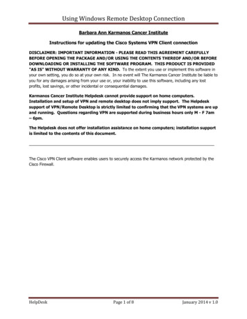
Sign ConventionSign ConventionRISAConnection uses a sign conventions shown below:Shear Connections:Moment Connections:20RISAConnection v12.0
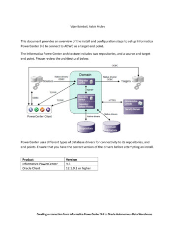
Sign ConventionVertical Diagonal Brace Connections:Chevron Brace Connections:General Reference Manual21
Sign ConventionHSS T Connections:Base Plate Connections:Axial LoadA positive axial load designates compression while a negative axial load designates tension. This is
RISAConnection RapidInteractiveStructuralAnalysisforConnections Version12.0-GeneralReference RISATech,Inc. 266