Transcription
CENTURY AUTO-DARKENING HELMETIM10068April, 2010SAFETY WARNINGS – READ BEFORE USINGWARNINGARC Rays can injure eyes and burn skin Before welding, always inspect helmet and filter lens to be sure they are fittedproperly, in good condition and not damaged. Check to see that the clear lens is clean and securely attached to the helmet. Always wear safety glasses or goggles under the welding helmet and protectiveclothing to protect your skin from radiation, burns and spatter. Ensure that optical radiation from other welder’s arcs in the immediate areadoes not enter in from behind the helmet and auto-darkening filter.Note: Auto-darkening filters in Century helmets are designed to protect the user against harmful ultra-violet and infrared rays both in the dark and light states. No matter what shade the filteris set to, the UV/IR protection is always present.TABLE OF CONTENTSPageSAFETY WARNINGS – READ BEFORE USINGHELMET INFORMATION, SPECIFICATIONSOPERATING INSTRUCTIONSCARTRIDGE OPERATIONS/FEATURESSHADE GUIDE SETTINGSHELMET CARE AND MAINTENANCETROUBLE SHOOTINGPARTS LISTS, WARRANTY INFORMATION12334567FUMES AND GASES can be dangerous to your health. Keep your head out of fumes. Use enough ventilation or exhaust at the arc or both to keep fumes and gasesfrom your breathing zone and general area. When welding with electrodes which require special ventilation such asstainless or hard facing (see instructions on container or MSDS) or onlead or cadmium plated steel and other metals or coatings which producehighly toxic fumes, keep exposure as low as possible and within applicable OSHA PEL and ACGIH TLV limits using local exhaust or mechanicalventilation. In confined spaces or in some circumstances, outdoors, arespirator may be required. Additional precautions are also requiredwhen welding on galvanized steel.OPERATOR’S MANUALCopyright Lincoln Global Inc. Century Equipment2345 Murphy Blvd. Gainesville, GA 30504 TEL: 866-236-0044Web Site: www.centuryequipment.netRefer to http://www.lincolnelectric.com/safetyfor additional safety information.1
CENTURY AUTO-DARKENING HELMETIM10068April, 2010SAFETY WARNINGS – READ BEFORE USINGWARNINGARC Rays can injure eyes and burn skin Before welding, always inspect helmet and filter lens to be sure they are fittedproperly, in good condition and not damaged. Check to see that the clear lens is clean and securely attached to the helmet. Always wear safety glasses or goggles under the welding helmet and protectiveclothing to protect your skin from radiation, burns and spatter. Ensure that optical radiation from other welder’s arcs in the immediate areadoes not enter in from behind the helmet and auto-darkening filter.Note: Auto-darkening filters in Century helmets are designed to protect the user against harmful ultra-violet and infrared rays both in the dark and light states. No matter what shade the filteris set to, the UV/IR protection is always present.TABLE OF CONTENTSPageSAFETY WARNINGS – READ BEFORE USINGHELMET INFORMATION, SPECIFICATIONSOPERATING INSTRUCTIONSCARTRIDGE OPERATIONS/FEATURESSHADE GUIDE SETTINGSHELMET CARE AND MAINTENANCETROUBLE SHOOTINGPARTS LISTS, WARRANTY INFORMATION12334567FUMES AND GASES can be dangerous to your health. Keep your head out of fumes. Use enough ventilation or exhaust at the arc or both to keep fumes and gasesfrom your breathing zone and general area. When welding with electrodes which require special ventilation such asstainless or hard facing (see instructions on container or MSDS) or onlead or cadmium plated steel and other metals or coatings which producehighly toxic fumes, keep exposure as low as possible and within applicable OSHA PEL and ACGIH TLV limits using local exhaust or mechanicalventilation. In confined spaces or in some circumstances, outdoors, arespirator may be required. Additional precautions are also requiredwhen welding on galvanized steel.OPERATOR’S MANUALCopyright Lincoln Global Inc. Century Equipment2345 Murphy Blvd. Gainesville, GA 30504 TEL: 866-236-0044Web Site: www.centuryequipment.netRefer to http://www.lincolnelectric.com/safetyfor additional safety information.1
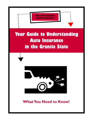
STMENTCROWNSHELLTILT ADJUSTMENTHELMET INFORMATIONThis Auto-Darkening Welding Helmet will automatically change from a light state (shade 4) to adark state (Shade 9-13) when arc welding starts.The filter automatically returns to a light state when the arc stops.Shade control adjustments can be made while welding.OPERATING INSTRUCTIONSHeadgear AdjustmentCROWNADJUSTMENTTILT ADJUSTMENTMatch your welding application to the shade indicated on the shade chart. (See Page 4) Operating temperature: 23 F 131 F(-5 C 55 C). Do not use or open the auto-darkening filter if damaged by shock, vibration or pressure. Keep the sensors and solar cell clean. Clean the filter cartridge using a soapy water solutionand soft cloth which should be damp but not saturated.This Auto-Darkening Welding Helmet is designed for use with GMAW, GTAW, MMAW, SMAW,FCAW welding, or Plasma Arc and air carbon arc cutting.The cartridge provides protection from harmful UV and IR radiation, in both dark and light JUSTMENTThe cartridge contains two sensors to detect the light from the welding arc, resulting in the lensdarkening to a selected welding shade. Do not use solvents or abrasive cleaning detergent. If cover lens is spattered or covered with dirt, it should be replaced immediately. Do not use the helmet without inside and outside cover lenses properly installed.SPECIFICATIONS97 x 44mm (3.82 x 1.73in)LCD Viewing AreaCartridge sizeUV/IR Protection110 x 90mm (4.33 x 3.54in)Up to Shade DIN 16 at all times2DIN 4DIN 9 to 13External knob - full adjustmentSolar cells - no battery requiredArc SensorsLight State ShadeVariable Welding ShadesShade ControlPower SupplyPower On/OffFully automatic0.0001 sec (1/10,000 sec)10 amps23 F 131 F (-5 C 55 C)Light to Dark Switching TimeTIG RatingOperating TemperatureStorage TemperatureTotal Weight-4 158 F (-20 C 70 C)496g (17.5 Oz.)Compliance(1)(1)ANSI Z87.1-2003Head Size Adjustment: Headband tightness is adjusted by pushing in the ratchet knob andturning to adjust to desired comfort level. This knob is located at the back of the helmet. HEADGEAR CROWN ADJUSTMENT is made by adjusting crown strap for vertical placement on thehead and snapping the pin into the hole to lock securely in place.Tilt: View angle is adjusted on both the left and right sides of helmet. Adjustment is made byloosening outside tension knobs of headgear and releasing tilt lever from its current location andmoving it to another location. It is recommended this adjustment be completed one side at atime. Retighten tension knobs when finished. The view angle adjustment needs to be set thesame for both tilt levers.Fore/Aft Adjustment: Fore/Aft adjustment is the distance between the user’s face and lens. Toadjust, loosen the outside tension knobs to allow for headgear to be repositioned to a differentlocation. This should be done one side at a time and both sides should be located the same forproper auto-darkening filter operation.CARTRIDGE OPERATION/FEATURESVariable Shade ControlThe shade can be adjusted from shade 9 to 13 based upon welding process or application (refer toShade selection chart on page 4). The variable shade control knob is mounted to shell for externaladjustment.Solar PowerThis helmet is powered by solar energy. As such, there is no battery that requires replacement.Headgear compliance with ANSI Z87.1 is without sweatband installed.23
STMENTCROWNSHELLTILT ADJUSTMENTHELMET INFORMATIONThis Auto-Darkening Welding Helmet will automatically change from a light state (shade 4) to adark state (Shade 9-13) when arc welding starts.The filter automatically returns to a light state when the arc stops.Shade control adjustments can be made while welding.OPERATING INSTRUCTIONSHeadgear AdjustmentCROWNADJUSTMENTTILT ADJUSTMENTMatch your welding application to the shade indicated on the shade chart. (See Page 4) Operating temperature: 23 F 131 F(-5 C 55 C). Do not use or open the auto-darkening filter if damaged by shock, vibration or pressure. Keep the sensors and solar cell clean. Clean the filter cartridge using a soapy water solutionand soft cloth which should be damp but not saturated.This Auto-Darkening Welding Helmet is designed for use with GMAW, GTAW, MMAW, SMAW,FCAW welding, or Plasma Arc and air carbon arc cutting.The cartridge provides protection from harmful UV and IR radiation, in both dark and light JUSTMENTThe cartridge contains two sensors to detect the light from the welding arc, resulting in the lensdarkening to a selected welding shade. Do not use solvents or abrasive cleaning detergent. If cover lens is spattered or covered with dirt, it should be replaced immediately. Do not use the helmet without inside and outside cover lenses properly installed.SPECIFICATIONS97 x 44mm (3.82 x 1.73in)LCD Viewing AreaCartridge sizeUV/IR Protection110 x 90mm (4.33 x 3.54in)Up to Shade DIN 16 at all times2DIN 4DIN 9 to 13External knob - full adjustmentSolar cells - no battery requiredArc SensorsLight State ShadeVariable Welding ShadesShade ControlPower SupplyPower On/OffFully automatic0.0001 sec (1/10,000 sec)10 amps23 F 131 F (-5 C 55 C)Light to Dark Switching TimeTIG RatingOperating TemperatureStorage TemperatureTotal Weight-4 158 F (-20 C 70 C)496g (17.5 Oz.)Compliance(1)(1)ANSI Z87.1-2003Head Size Adjustment: Headband tightness is adjusted by pushing in the ratchet knob andturning to adjust to desired comfort level. This knob is located at the back of the helmet. HEADGEAR CROWN ADJUSTMENT is made by adjusting crown strap for vertical placement on thehead and snapping the pin into the hole to lock securely in place.Tilt: View angle is adjusted on both the left and right sides of helmet. Adjustment is made byloosening outside tension knobs of headgear and releasing tilt lever from its current location andmoving it to another location. It is recommended this adjustment be completed one side at atime. Retighten tension knobs when finished. The view angle adjustment needs to be set thesame for both tilt levers.Fore/Aft Adjustment: Fore/Aft adjustment is the distance between the user’s face and lens. Toadjust, loosen the outside tension knobs to allow for headgear to be repositioned to a differentlocation. This should be done one side at a time and both sides should be located the same forproper auto-darkening filter operation.CARTRIDGE OPERATION/FEATURESVariable Shade ControlThe shade can be adjusted from shade 9 to 13 based upon welding process or application (refer toShade selection chart on page 4). The variable shade control knob is mounted to shell for externaladjustment.Solar PowerThis helmet is powered by solar energy. As such, there is no battery that requires replacement.Headgear compliance with ANSI Z87.1 is without sweatband installed.23
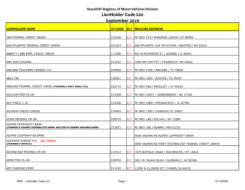
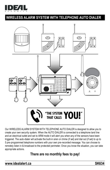
ALWAYS TEST TO BE SURE THE ADF CARTRIDGE IS CHARGEDBEFORE WELDING. The helmet can be placed in sunlight to charge. Donot store the helmet in a dark cabinet or other storage area for long periods.While welding, the arc also charges the ADF cartridge.Data from ANSI Z49.1-2005workpiece.(2) These values apply where the actual arc is clearly seen. Experience has shown that lighter filters may be used when the arc is hidden by thethe yellow or sodium line the visible light of the (spectrum) operation .below the minimum. In oxyfuel gas welding or cutting where the torch produces a high yellow light, it is desirable to use a filter lens that absorbs(1) As a rule of thumb, start with a shade that is too dark, then go to a lighter shade which gives sufficient view of the weld zone without goingHeavyMediumLightOxygen cuttingHeavyMediumLightGas weldingOver 61 to 6Under 1Over 15025 to 150Under 25Over 1/21/8 to 1/2Under 1/8in.–Torch soldering–Torch 00Less than 300(2)400-800100-40020-100Less than 20Plasma arc weldingArc cuttingAir carbon5 or 64 or 53 or 4Over 12.73.2 to 12.7Under 3.26 or 85 or 64 or 5mmPLATE THICKNESSCarbon arc weldingPlasma arc cutting(Heavy)(Light)500-1000Less than 500150-50050-150Less than 50weldingGas tungsten arc250-500160-25060-160Less than 60cored arc weldingwelding and fluxGas metal arc–––10981110861110108810101071423 or 414129SHADE GUIDE SETTINGS1412106 to 81412141210141211–weldingShielded metal arcMore than 8 (6.4)5-8 (4–6.4)3-5 (2.5–4)Less than 3 (2.5)250-550160-25060-160Less than 60111087141210–OPERATION1/32 in. (mm)ELECTRODE SIZECURRENT (A)ARCSHADEPROTECTIVEMINIMUM(COMFORT)SHADE NO.SUGGESTED(1)GUIDE FOR SHADE NUMBERSHELMET CARE AND MAINTENANCEReplacing Front Cover Lens: Replace the front cover lens if it is damaged– cracked, soiled or pitted. Place your finger or thumb into recess (C) at thebottom edge of the cover lens and flex the lens upwards until it releases fromthe edges marked A and B. (Refer to figure 1).GUIDE FOR SHADE NUMBERSOPERATIONELECTRODE SIZE1/32 in. (mm)ARCCURRENT (A)MINIMUMPROTECTIVESHADESUGGESTED(1)SHADE NO.(COMFORT)Shielded metal arcweldingLess than 3 (2.5)3-5 (2.5–4)5-8 (4–6.4)More than 8 (6.4)Less than 6060-160160-250250-550781011–101214Gas metal arcwelding and fluxcored arc weldingLess than 6060-160160-250250-5007101010–111214Gas tungsten arcweldingLess than 5050-150150-5008810101214Less than 500500-100010111214Less than 2020-100100-400400-8006810116 to 8101214Less than 300300-400400-800891091214Torch brazing––3 or 4Torch soldering––2Carbon arc welding––14Air carbonArc cutting(Light)(Heavy)Plasma arc weldingPlasma arc cutting(2)(Light)(2)(Medium)(Heavy)(2)in.PLATE THICKNESSmmGas weldingLightMediumHeavyUnder 1/81/8 to 1/2Over 1/2Under 3.23.2 to 12.7Over 12.74 or 55 or 66 or 8Oxygen cuttingLightMediumHeavyUnder 11 to 6Over 6Under 2525 to 150Over 1503 or 44 or 55 or 6(1) As a rule of thumb, start with a shade that is too dark, then go to a lighter shade which gives sufficient view of the weld zone without goingReplace the Inside Cover Lens: if it is damaged (cracked, soiled or pitted).Place your fingernail in recess above cartridge view window and flex lensupwards until it releases from edges of cartridge view window.Change the Shade Cartridge (See figure 2)Fitting New Cartridge: Take the new shade cartridge and pass the potentiometer cable under the wire loop before placing the cartridge into its retaining frame inside the helmet. Hinge down the wire loop and ensure the frontedge of the loop (D) is properly retained under the retaining lugs (E) asshown in (figure 3).Position the shade potentiometer to the inside of the helmet with the shaftprotruding through the hole. Secure potentiometer to shell. On the outside ofthe helmet, push the shade control knob onto the shaft.Cleaning: Clean helmet by wiping with a soft cloth. Clean cartridge surfacesregularly. Do not use strong cleaning solutions. Clean sensors and solar cellswith soapy water solution and a clean cloth and wipe dry with a lint-free cloth.Do NOT submerge shade cartridge in water or other solution.Storage: Store in a clean, dry location.Figure 1Figure 2Figure 3below the minimum. In oxyfuel gas welding or cutting where the torch produces a high yellow light, it is desirable to use a filter lens that absorbsthe yellow or sodium line the visible light of the (spectrum) operation .(2) These values apply where the actual arc is clearly seen. Experience has shown that lighter filters may be used when the arc is hidden by theworkpiece.Data from ANSI Z49.1-2005If your helmet does not include any one of the shades referenced above, it isrecommended you use the next darker shade.Figure 14Figure 25Figure 3
ALWAYS TEST TO BE SURE THE ADF CARTRIDGE IS CHARGEDBEFORE WELDING. The helmet can be placed in sunlight to charge. Donot store the helmet in a dark cabinet or other storage area for long periods.While welding, the arc also charges the ADF cartridge.Data from ANSI Z49.1-2005workpiece.(2) These values apply where the actual arc is clearly seen. Experience has shown that lighter filters may be used when the arc is hidden by thethe yellow or sodium line the visible light of the (spectrum) operation .below the minimum. In oxyfuel gas welding or cutting where the torch produces a high yellow light, it is desirable to use a filter lens that absorbs(1) As a rule of thumb, start with a shade that is too dark, then go to a lighter shade which gives sufficient view of the weld zone without goingHeavyMediumLightOxygen cuttingHeavyMediumLightGas weldingOver 61 to 6Under 1Over 15025 to 150Under 25Over 1/21/8 to 1/2Under 1/8in.–Torch soldering–Torch 00Less than 300(2)400-800100-40020-100Less than 20Plasma arc weldingArc cuttingAir carbon5 or 64 or 53 or 4Over 12.73.2 to 12.7Under 3.26 or 85 or 64 or 5mmPLATE THICKNESSCarbon arc weldingPlasma arc cutting(Heavy)(Light)500-1000Less than 500150-50050-150Less than 50weldingGas tungsten arc250-500160-25060-160Less than 60cored arc weldingwelding and fluxGas metal arc–––10981110861110108810101071423 or 414129SHADE GUIDE SETTINGS1412106 to 81412141210141211–weldingShielded metal arcMore than 8 (6.4)5-8 (4–6.4)3-5 (2.5–4)Less than 3 (2.5)250-550160-25060-160Less than 60111087141210–OPERATION1/32 in. (mm)ELECTRODE SIZECURRENT (A)ARCSHADEPROTECTIVEMINIMUM(COMFORT)SHADE NO.SUGGESTED(1)GUIDE FOR SHADE NUMBERSHELMET CARE AND MAINTENANCEReplacing Front Cover Lens: Replace the front cover lens if it is damaged– cracked, soiled or pitted. Place your finger or thumb into recess (C) at thebottom edge of the cover lens and flex the lens upwards until it releases fromthe edges marked A and B. (Refer to figure 1).GUIDE FOR SHADE NUMBERSOPERATIONELECTRODE SIZE1/32 in. (mm)ARCCURRENT (A)MINIMUMPROTECTIVESHADESUGGESTED(1)SHADE NO.(COMFORT)Shielded metal arcweldingLess than 3 (2.5)3-5 (2.5–4)5-8 (4–6.4)More than 8 (6.4)Less than 6060-160160-250250-550781011–101214Gas metal arcwelding and fluxcored arc weldingLess than 6060-160160-250250-5007101010–111214Gas tungsten arcweldingLess than 5050-150150-5008810101214Less than 500500-100010111214Less than 2020-100100-400400-8006810116 to 8101214Less than 300300-400400-800891091214Torch brazing––3 or 4Torch soldering––2Carbon arc welding––14Air carbonArc cutting(Light)(Heavy)Plasma arc weldingPlasma arc cutting(2)(Light)(2)(Medium)(Heavy)(2)in.PLATE THICKNESSmmGas weldingLightMediumHeavyUnder 1/81/8 to 1/2Over 1/2Under 3.23.2 to 12.7Over 12.74 or 55 or 66 or 8Oxygen cuttingLightMediumHeavyUnder 11 to 6Over 6Under 2525 to 150Over 1503 or 44 or 55 or 6(1) As a rule of thumb, start with a shade that is too dark, then go to a lighter shade which gives sufficient view of the weld zone without goingReplace the Inside Cover Lens: if it is damaged (cracked, soiled or pitted).Place your fingernail in recess above cartridge view window and flex lensupwards until it releases from edges of cartridge view window.Change the Shade Cartridge (See figure 2)Fitting New Cartridge: Take the new shade cartridge and pass the potentiometer cable under the wire loop before placing the cartridge into its retaining frame inside the helmet. Hinge down the wire loop and ensure the frontedge of the loop (D) is properly retained under the retaining lugs (E) asshown in (figure 3).Position the shade potentiometer to the inside of the helmet with the shaftprotruding through the hole. Secure potentiometer to shell. On the outside ofthe helmet, push the shade control knob onto the shaft.Cleaning: Clean helmet by wiping with a soft cloth. Clean cartridge surfacesregularly. Do not use strong cleaning solutions. Clean sensors and solar cellswith soapy water solution and a clean cloth and wipe dry with a lint-free cloth.Do NOT submerge shade cartridge in water or other solution.Storage: Store in a
does not enter in from behind the helmet and auto-darkening filter. Note: Auto-darkening filters in Century