Transcription
MSHA HANDBOOK SERIESU.S. Department of LaborMine Safety and Health AdministrationMine Safety and Health EnforcementDecember 2020Handbook Number: PH20-V-5Electrical InspectionProcedures Handbook
PREFACEThis handbook sets forth procedures for MSHA personnel to follow when conductinginvestigations and inspections of mines and facilities. Volume I provides guidance forelectrical specialist, while Volume II provides guidance to MSHA general inspectorswho encounter mine electrical systems and electric-powered equipment during thecourse of their inspections.Previously issued instructions for this same subject material are superseded by thishandbook. Compliance related instructions that are contained in the MSHA ProgramPolicy Manual remain in effect.Not all procedures and requirements are applicable for all mine types. Any deviationfrom the procedures outlined in this handbook should be based on the inspector’sprofessional judgement and discussion with the inspector’s supervisor, and considerconditions, practices, and circumstances specific to the mine.
Table of ContentsVOLUME I . 1CHAPTER 1 - INTRODUCTION . 1-1A.B.C.D.INSPECTION SCHEDULES . 1-1EQUIPMENT AND SUPPLIES . 1-3REFERENCES. 1-4ELEMENTS OF ELECTRICAL INSPECTIONS . 1-4CHAPTER 2 - GROUNDING . 2-1A.B.C.D.E.F.G.H.I.GENERAL . 2-1APPROVED GROUNDING METHODS . 2-1RESISTANCE GROUNDED SYSTEMS. 2-2GROUNDED PHASE PROTECTION IN RESISTANCE GROUNDED SYSTEMS . 2-7GROUND CHECK MONITOR TEST PROCEDURES . 2-7LIGHTNING ARRESTER GROUND FIELDS . 2-10SILICON DIODE GROUNDING TEST PROCEDURES. 2-11METAL BATTERY CONNECTOR HOUSINGS . 2-12TESTING OF GROUNDING SYSTEMS IN METAL AND NONMETAL MINES . 2-13CHAPTER 3 - CABLE INSULATION, PROTECTION, AND SPLICING . 3-1A.B.C.D.GENERAL . 3-1OUTER JACKET OR INSULATION DAMAGE IN CABLES . 3-1TRAILING CABLES . 3-2CONTINUITY OF SHIELDING IN CABLE SPLICES . 3-4CHAPTER 4 – OVERCURRENT PROTECTION . 4-1A.B.C.D.E.F.G.GENERAL . 4-1CABLE AND CONDUCTOR AMPACITY . 4-1CONDUCTOR AMPACITY FOR MOTOR CIRCUITS . 4-2GENERAL OVERCURRENT PROTECTION FOR ELECTRIC EQUIPMENT AND CIRCUITS . 4-4OVERLOAD AND SHORT CIRCUIT PROTECTION FOR MOTOR CIRCUITS. 4-5SHORT CIRCUIT PROTECTION FOR TRAILING CABLES . 4-8EXAMPLES OF NONCOMPLIANCE . 4-8CHAPTER 5 – HIGH VOLTAGE CIRCUIT BREAKERS AND SUBSTATIONS . 5-1A.B.C.D.E.F.G.H.I.SAFETY PRECAUTIONS FOR HIGH VOLTAGE TESTING . 5-1PROTECTION OF HIGH VOLTAGE CIRCUITS . 5-5UNDERVOLTAGE PROTECTION. 5-5GROUNDED-PHASE PROTECTION . 5-5CURRENT TRANSFORMERS AND RELAY BURDEN . 5-8HOW TO CALCULATE SHORT CIRCUIT PROTECTION. 5-9HOW TO CALCULATE OVERCURRENT PROTECTION . 5-9TESTING METHODS . 5-17SURFACE TRANSFORMER STATION GUIDELINES . 5-18CHAPTER 6 - PERMISSIBILITY . 6-1A.B.INSPECTION PROCEDURES . 6-1FIELD MODIFICATION PROCEDURES . 6-4
Table of ContentsC.D.FIELD MODIFICATION REPORTS . 6-5DISTRICT FIELD CHANGES. 6-5CHAPTER 7 – GENERAL. 7-1A.B.GUIDELINES FOR USING THE NATIONAL ELECTRICAL CODE . 7-1GUIDELINES FOR DETERMINING PORTABLE, MOBILE, AND STATIONARY ELECTRIC EQUIPMENT LOCATEDON THE SURFACE . 7-2C. GUIDELINES FOR PERMITTING NON-EXPLOSION-PROOF AIR HEATING UNITS IN HAZARDOUS LOCATIONSON THE SURFACE . 7-2D. ELECTRICAL SWITCH EVALUATION CRITERIA . 7-3E. LIGHTNING ARRESTERS . 7-4F. INTERMACHINE ARCING TEST PROCEDURES . 7-5G. EVALUATING ELECTRIC EQUIPMENT MAINTENANCE PROGRAMS FOR COAL MINES . 7-7H. ADDITIONAL PROCEDURES WHEN USING A SAFETY CIRCUIT TESTER . 7-7I. ELECTROMAGNETIC INTERFERENCE . 7-8J. LONGWALL ELECTRICAL INSPECTIONS . 7-8VOLUME II. II-1CHAPTER 1 - INTRODUCTION . II-1CHAPTER 2 - GROUNDING . II-1CHAPTER 3 - CABLE INSULATION, PROTECTION, AND SPLICING . II-2A.B.C.CABLE SPLICES . II-3HIGH POTENTIAL/HIGH VOLTAGE CABLES (MNM: 650 VAC; COAL: 1,000 VAC) . II-3LOW/MEDIUM VOLTAGE CABLES (MNM: 650 VAC, COAL: 1000 VOLTS). II-4CHAPTER 4 - HIGH VOLTAGE SUBSTATIONS AND DISTRIBUTION . II-4A.B.C.OVERHEAD DISTRIBUTION LINES . II-5SURFACE ELECTRICAL DISTRIBUTION CIRCUITS . II-6UNDERGROUND ELECTRICAL DISTRIBUTION CIRCUITS . II-7CHAPTER 5 - PERMISSIBILITY . II-7CHAPTER 6 - ELECTRICAL EQUIPMENT AND OTHER INSPECTION ELEMENTS . II-8A.B.C.DOUBLE INSULATED EQUIPMENT . II-8ELECTRICAL EQUIPMENT COMPONENTS . II-8WORK PRACTICES . II-9APPENDIX A – PERMISSIBILITY . II-12
ELECTRICAL INSPECTION PROCEDURES HANDBOOKVOLUME IVOLUME ICHAPTER 1 - INTRODUCTIONA.Inspection SchedulesMany of the requirements of 30 CFR concerning electrical circuits and equipment arevery technical in nature. A thorough knowledge of electrical theory, mine powersystems, and electric equipment is essential if inspection personnel are to properlyimplement these requirements without creating hazards to themselves or to miners.When mine inspectors encounter electrical problems that require special electricalexpertise, the assistance of an electrical specialist should be requested. The term“electrical specialist” as used in this document refers to a person with an extensivebackground in mine electrical systems and equipment. Examples include electricalengineers, electrical inspectors, and others who have the education and experiencenecessary to safely evaluate mine electrical systems and equipment. Requests forassistance from electrical specialists should be forwarded through the inspector'simmediate supervisor and should outline the nature of the problem with as muchbackground information as possible.During each electrical inspection, the electrical specialist shall inspect an adequateportion of the electric circuits, electric equipment, and mechanical equipment at eachmine to ascertain that the equipment and circuits are being maintained in accordancewith the Federal Mine Safety and Health Act of 1977 (Mine Act), as amended, andMSHA’s standards.During each electrical inspection, the electrical specialist shall evaluate the examinationand maintenance program at the mine to ensure that it is adequate to maintain theelectrical equipment and circuits in safe condition. Requirements for examination andmaintenance of electrical equipment and circuits in coal mines are listed in 30 CFR75.512, 75.800, 75.821, 75.832, 75.900, 77.502, 77.800, and 77.900. Requirements forexamination and testing of grounding systems in metal and nonmetal mines are listedin 56.12028 and 57.12028. An effective examination and maintenance program shouldbe in place at all mines.Improvements in electrical technology in the mining industry and the correspondingneed for greater expertise by electrical specialists require electrical inspection personnelto continue their education in this technology. In addition to MSHA training, allelectrical specialists should keep abreast of the latest developments in mine electricaltechnology by studying reference material, technical publications, and text books and1-1
ELECTRICAL INSPECTION PROCEDURES HANDBOOKVOLUME Iby attending seminars (with the approval of district management) pertaining toelectrical technology.1-2
ELECTRICAL INSPECTION PROCEDURES HANDBOOKB.VOLUME IEquipment and SuppliesIn addition to the basic safety equipment and supplies required for all mine inspectors,the following equipment and supplies should be provided for electrical specialists: Electrically-rated safety shoes and safety rubber boots 100% cotton or fire-resistant (FR) rated coveralls Class 2 high-voltage gloves with leather protectors Class 0 low-voltage gloves with leather protectors Padlock, hasp extender, and suitable tags for lockout/tagout Non-contact AC voltage detector appropriately rated for the circuits, equipment,and environmental conditions encountered during electrical inspections Multimeter(s) for measuring voltage, current, and resistance. Meters must beappropriately rated for the circuits, equipment, and environmental conditionsencountered during electrical inspections Earth-resistance tester Insulation resistance tester appropriately rated for the circuits, equipment, andenvironmental conditions encountered during electrical inspections Safety Circuit Tester, Becker/SMC Model C-3100 or equivalent (used to verifycompliance with 30 CFR 75.900 and 75.902) Set of flat feeler gauges (0.003, 0.004, 0.005, 0.007 and 0.009 inch) Set of round feeler gauges (0.007, 0.009 and 0.011 inch) Caliper rule BinocularsMultimeters and other test equipment should be calibrated and maintained as specifiedby the manufacturer. Electrical specialists who are exposed to electrical hazards shouldbe provided with appropriate personal protective equipment (PPE). Electricalspecialists should be knowledgeable in the selection, use, limitations, inspection,donning, doffing, and maintenance of PPE. PPE should be maintained in a safe, reliablecondition and should be inspected or tested as recommended by the manufacturer andrequired by the Occupational Safety and Health Administration (OSHA). For example,High voltage gloves should be tested every six months in accordance with ASTM F49697, "Standard Specification for In-Service Care of Insulating Gloves and Sleeves."District Managers have the authority to determine the specialized equipment theirelectrical specialist need to conduct on-site activities. Electrical specialists will beprovided appropriate training before using such devices to prevent exposing1-3
ELECTRICAL INSPECTION PROCEDURES HANDBOOKVOLUME Ithemselves or others to potential hazards. A standardized list for specializedequipment should be requested from Management & Program Analyst or Managementor Procurement Officer.C.ReferencesAdequate technical reference material should be available at each district and fieldoffice for the use of electrical engineers and electrical specialists and should include thefollowing publications at a minimum:1. Mine Power Systems - U.S. Bureau of Mines IC92582. National Electrical Code, 1968 and later editions as needed3. National Electrical Safety Code, 1968 and later editions as needed4. Recommended Practice for Grounding Industrial and Commercial Power Systems –IEEE Standard 142-1972 and later editions as needed5. IEEE Standard Dictionary of Electrical and Electronics Terms – IEEE Standard 1001972 and later editions as needed6. General Electric Distribution Transformer Manual - Publication GET-2485B7. Ugly’s Electrical References (Jones and Bartlett) or equivalent8. Mine Electricity, Metal/Nonmetal Surface and Underground Entry Level Training –National Mine Health and Safety Academy Publication CI 8D.Elements of Electrical InspectionsElectrical inspections can vary greatly depending on the type of mine or facility. Thefollowing list is not intended to be comprehensive, but may be used as a guide toremind electrical specialists of some of the most common enforcement elements of anelectrical inspection.1. Substations, Transformers, and Switchgeara. Fences and enclosuresb. Vertical and horizontal clearance from live partsc. Disconnecting devicesd. Primary overcurrent protection for transformerse. Transformer connectionsf. System grounding (solid grounded, resistance grounded, ungrounded, etc.)g. Grounding resistors and connections1-4
ELECTRICAL INSPECTION PROCEDURES HANDBOOKVOLUME Ih. Ground fieldsi. Frame grounding of transformers, circuit breakers, etc.j.Lightning protectionk. Circuit breakers and auxiliary devices1) Overcurrent relays2) Current transformer ratios3) Ground check circuits4) Ground fault relays5) Undervoltage relays2. Power Centersa. Frame groundingb. Incoming disconnecting devicesc. Primary overcurrent protection of transformersd. Type of neutral connection (direct or derived)e. Grounding resistorsf. Circuit breakers and auxiliary devices (grounded phase, undervoltage, etc.)g. Lightning and surge protectionh. Disconnecting means for loads served by the power centeri. Cable couplers and receptaclesj.Ground check circuits3. General Distributiona. Circuit identificationb. Type and capacity of cables or conductorsc. Mechanical protection of cables or conductorsd. Conductor clearancee. Bushings and fittings where cables enter enclosuresf. Splices, terminations, and couplersg. Disconnecting devicesh. Switch houses and load centers1-5
ELECTRICAL INSPECTION PROCEDURES HANDBOOKVOLUME I4. General Circuit Protectiona. Ampacity of conductorsb. Overload and short circuit protectionc. Proper installation and mounting of fuses, circuit breakers, and otherprotective devices5. Stationary Electric Equipmenta. Overload and short circuit protectionb. Frame groundingc. Safe operating controlsd. Cables and wiring, fittings, insulatorse. Fire protectionf. Cleanliness of equipmentg. Permissibility of equipment in face areas and return airways6. Mobile Equipmenta. Overload and short circuit protectionb. Frame groundingc. Safe Operating controlsd. Cables and wiring, entrance glands, mechanical protectione. Fire protectionf. Cleanliness of equipmentg. Sand riggingh. Brakesi. Lightsj.Permissibility of equipment in face areas and return airwaysk. Proximity detection systems7. Trailing Cablesa. Condition of outer jacket, conductor insulation and splicesb. Short circuit protectionc. Size of dual element fusesd. Trip element and setting of circuit breakers1-6
ELECTRICAL INSPECTION PROCEDURES HANDBOOKVOLUME Ie. Visible disconnecting devicesf. Identification of cablesg. Continuity of grounding conductorsh. Mechanical protection8. Recordsa. Map of the electrical system (coal mines)b. List of qualified electricians (coal mines)c. Records of monthly circuit breaker tests (coal mines)d. Records of weekly examinations of electric equipment (coal mines)e. Record of resistance measurements for grounding systems (metal andnonmetal mines)9. Work Practicesa. Lock Out and Tag Out Proceduresb. Troubleshooting and Testing Practicesc. Installation and Maintenance Practices1-7
ELECTRICAL INSPECTION PROCEDURES HANDBOOKVOLUME ICHAPTER 2 - GROUNDINGA.General30 CFR contains requirements that relate to both system grounding and equipmentgrounding. System grounding refers to the way that current carrying conductors in thedistribution system are intentionally connected (or not connected) to earth.Most distribution systems encountered by inspectors will be grounded in some manner.However, ungrounded systems are used at some mines and facilities, and it isimportant for the inspector to understand the different ways that grounded systemsand ungrounded systems respond to fault conditions. In general, ground faults ingrounded systems result in current flow that is of sufficient magnitude to operateovercurrent devices. Ground faults in ungrounded systems may not produce sufficientcurrent to operate overcurrent devices, although other means of ground fault detectionmay be used.Equipment grounding refers to the way that metallic frames and casings are connectedtogether and to earth. The metal parts of all equipment that can become energized dueto insulation failure must be grounded.B.Approved Grounding MethodsFor coal mines, inspectors shall not accept any method of grounding that does notcomply with the requirements of Subpart H of 30 CFR Parts 75 and 77. Program PolicyManual (PPM) Volume V provides significant guidance regarding the application ofSubpart H and should be consulted by inspectors when questions about the adequacyof different grounding methods arise.For metal and nonmetal mines, inspectors shall not accept any method of groundingthat does not comply with 30 CFR 56.12025, 56.12026, 56.12027, 57.12025, 57.12026, and57.12027.Grounded SystemsAn inspector shall not approve any method of grounding that does not include a solidconnection to a grounding conductor which extends to the grounded point of the powersource. The grounded power conductor of a solidly grounded alternating current powersystem may serve as the equipment grounding conductor only between the groundedpoint of the power source and the grounded enclosure of the service disconnectingmeans for a building or other stationary facility. The grounded point of the powersource and the metallic enclosure of each service disconnecting means shall be2-1
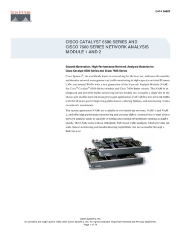
ELECTRICAL INSPECTION PROCEDURES HANDBOOKVOLUME Iconnected to an acceptable grounding medium, such as metal waterlines having lowresistance to earth, a low-resistance ground field, etc.Ungrounded SystemsWhen multiple units of equipment are supplied by the same ungrounded system, theframes of such equipment must be grounded to the same grounding medium (groundfield, grounding electrode, etc.) to ensure that there is no difference in potentialbetween metal enclosures and the earth.The connecting of different metallic enclosures of electric equipment receiving powerfrom the same ungrounded alternating current system to different, unconnectedgrounding mediums does not ensure that there is no difference in potential betweensuch enclosures and earth, and has resulted in several electrocutions. Therefore, thismethod of grounding is not acceptable.C.Resistance Grounded SystemsResistance grounded systems are mandated for certain circuits in coal mines. Specificrequirements are found in 30 CFR 75.801, 75.802, 75.901, 77.801, 77.802, and 77.901. PPMVolume V also contains additional guidance on grounding resistors and groundingtransformers and should be consulted when questions regarding resistance groundingarise.Resistance grounded systems are not mandated for metal and nonmetal mines.However, when these systems are installed, they must be carefully evaluated byelectrical specialists to ensure that they are maintained in safe condition. Theinformation presented in this section is intended to help electrical specialists evaluatethe safety of resistance grounded systems and take appropriate enforcement action.Grounding ResistorsThe purpose of the grounding resistor is to limit the ground fault current to apredetermined value during fault conditions. The current value is selected to limit thevoltage that will appear on the frames of equipment during a phase-to-ground faultwhile providing sufficient ground fault current for reliable relaying.Grounding resistors used in mine power systems usually have a current rating of 15, 25,or 50 amperes, depending on the particular system for which the resistor is designed.The resistance (R) of a grounding resistor can be calculated from the phase-to-neutralvoltage of the system (V) and the current rating of the resistor (IR), using Ohm’s Law.2-2
ELECTRICAL INSPECTION PROCEDURES HANDBOOKVOLUME IExample:V 2,400 volts, IR 25 amperesR R VIR2,400 volts25 amperes 96𝛺𝛺A person standing on the earth while touching the frame of a piece of equipmentconnected to the grounding circuit is essentially in parallel with the groundingconductor (See Figure 1). During a phase-to-ground fault, most of the voltage dropappearing across the grounding conductor will also appear across the person’s body.For this reason, it is critical to keep the grounding conductor resistance as low aspossible.30 CFR 75.801 requires grounding resistors in underground high voltage systems tolimit the voltage drop in the grounding circuit external to the grounding resistor to 100volts. Consequently, if a 25-ampere grounding resistor is used as shown in the circuit inFigure 1, the maximum impedance of the grounding conductor cannot exceed 4.26ohms.Figure 1 - Touch potential of resistance grounded system under fault conditions (refer toAppendix F for calculations)2-3
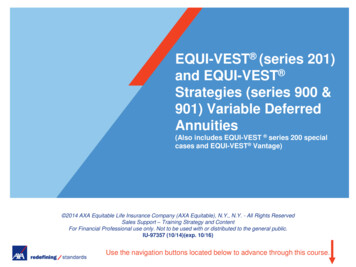
ELECTRICAL INSPECTION PROCEDURES HANDBOOKVOLUME IWhen the rating of a grounding resistor is unclear, copy the nameplate data and consultwith the manufacturer to verify that the resistor is rated for the maximum fault currentcontinuously. Electrical specialists should carefully examine high voltage groundingresistors for improper connection in the circuit, improper rating, broken terminalconnections, and broken jumpers between resistor coils. When heat is observed risingfrom a grounding resistor, the following conditions may exist:1) a grounded-phase condition, probably in the cable; and2) an inoperative grounded-phase relay or trip circuit in the circuit breaker.Analog multimeters or digital multimeters with voltage compensation should be usedwhen measuring grounding resistors, due to possible galvanic interference.Resistance Grounded Circuits and EquipmentSystem neutrals are normally obtained by using source transformers or generators withwye-connected secondary windings. The neutral is then readily available for groundingpurposes. For delta-connected systems, grounding transformers are used to derive aneutral that is then grounded through a suitable resistor.Figures 2 shows in simplified form the proper method of connecting resistancegrounded circuits extending underground.Figure 2 - Properly connected resistance grounded circuitsThe type of grounding transformer most commonly used is a three-phase zigzagtransformer. The impedance of the transformer to three-phase currents is high, so that2-4
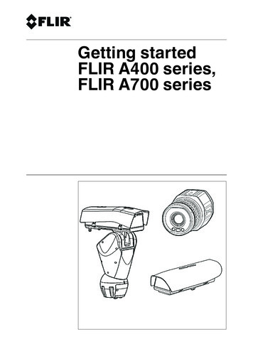
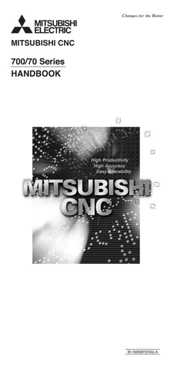
ELECTRICAL INSPECTION PROCEDURES HANDBOOKVOLUME Iwhen there is no fault on the system, only a small magnetizing current flows in thetransformer windings. The transformer impedance to ground-fault current, however, islow. The transformer divides the ground current into three equal components; thesecurrents are in phase with each other and flow in the three windings of the groundingtransformer.The method of winding is such that when these three equal currents flow, the current inone section of the winding of each leg of the core is in a direction opposite to that in theother section of the winding of that leg. The only magnetic flux that results from thezero-sequence fault currents is the leakage flux about each winding section. Thisarrangement accounts for the low impedance of the transformer to ground-fault current(See Figure 3). The connections and current distributions in a wye-delta groundingtransformer bank are shown in Figure 4.Figure 3 - Zigzag three-phase grounding transformerExample of how to calculate the proper size grounding transformer:Transformer kVA VxI1000, whereV phase-to-neutral voltage 2,400 volts, andI rated ground fault current 25 amperes.Minimum size grounding transformer 60 kVATransformer banks connected wye on the primary side and supplied power from aresistance-grounded circuit shall not have the primary neutral grounded. Such aconfiguration as shown in Figure 5 would provide the circuit with two neutrals (oneresistance grounded and one solidly grounded) and would effectively short circuit thegrounding resistor.2-5
ELECTRICAL INSPECTION PROCEDURES HANDBOOKVOLUME IFigure 4 - Connections and current distribution in a wye-delta grounding transformerFigure 5 - An unacceptable ground fault configuration. This system will not comply sincefault current will flow through the second neutral (connected to ground field 2), effectivelyshorting out the grounding resistor during fault conditions.2-6
ELECTRICAL INSPECTION PROCEDURES HANDBOOKD.VOLUME IGrounded Phase Protection in Resistance Grounded SystemsInspectors shou
IEEE Standard 142-1972 and later editions as needed 5. IEEE Standard Dictionary of Electrical and Electronics Terms – IEEE Standard 100-1972 and later editions as needed 6. General Electric Distribution Transformer Manual - Publication GET-2485B 7. Ugly’s El