Transcription
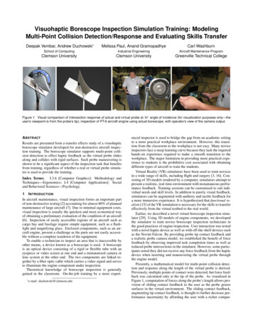
FOR REFERENCE ONLYB767 CF6-80C Borescope RecurrentTraining2020
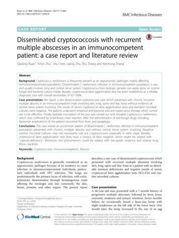
FOR REFERENCE ONLYIntroductionBorescope inspection is an important practice on anyaircraft. Inspection requirements vary by engine type, andin-service activity. Additionally, an inspection may also becalled when performance has started to lag.Whenever you perform your inspection, a special focusneeds to fall on the engine and techniques required. Amodern jet engine is made to withstand extremecircumstances along with efficient and prolonged use, butthey are still subject to damage and wear. Routineinspection and maintenance can help prevent mostinstances of engine failure and prolong the life of the enginein service. During engine borescope inspection the operatorcan spot issues that indicate future, or imminent failure.During a complete inspection using a borescope, mostissues can be found before they become an issue. Thismodule has been prepared as part of your continuationtraining.Remember to always refer to the correct and currentissue of the AMM prior and during an inspection. Fortraining purposes please study the information from theaircraft maintenance manual attached.
For Training OnlyCF6-80C SERIES ENGINES767AIRCRAFT MAINTENANCE MANUALENGINE - INSPECTION/CHECK1.GeneralA. This procedure contains these tasks:B.2.(1)Borescope Inspection(2)Continue-In-Operation Limits(3)Unusual Condition Inspection(4)External Engine Inspection(5)Radiographic Engine Inspection(6)Ultrasonic Inspection(7)Inspection of Engines Involved in Accidents or Incidents(8)Compressor Rear Frame (CRF) Oil Leakage Inspection(9)Oil System Leakage Inspection(10)Inlet Gearbox Assembly - Horizontal Bevel Gear Seal Borescope Inspection(11)Inclement Weather Flameout Inspection.(12)Inlet Gearbox Spline Nozzle Borescope Inspection(13)Inlet Gearbox Spline Backlash Borescope Inspection(14)Combustion Section Inspection (scheduled maintenance requirement)(15)High Pressure Turbine Inspection (scheduled maintenance requirement)(16)Volcanic Ash/Sand Ingestion Inspection.The maintenance of the engine makes it necessary to do inspection checks at intervals. Theinspection requirements and limits throughout this manual are based on operation within specifiedlimits. In addition to the regular inspections, there are those necessary when the engine has beenoperated outside of the specified limits (for example, overspeed or overtemperature). There are alsospecial inspections necessary for engines to which unusual conditions are applied. These includeaircraft accidents and incidents specified in ICAO Annex 13. Also included are other unusualincidents such as a hangar or ramp fire, or an accident during engine transport, handling or storage.This procedure gives the inspection checks necessary after an overlimit operation and the specialinspection checks necessary for engines exposed to unusual conditions.TASK 72-00-00-206-146-H00Borescope Inspection(Figure 601, Figure 602, Figure 603, Figure 604, Figure 606, Figure 612 or Figure 613 or Figure 614 orFigure 615, Figure 616, Figure 617, Figure 618, Figure 618, Figure 620, Figure 621, Figure 622,Figure 623, Figure 625, Figure 626 and Figure 627)A.General(1) This task gives instructions to examine the internal areas of the engine along the flow of theprimary airstream.(2)Use the borescope ports for access to examine the internal engine areas. You do not have todisassemble the engine to do this task.(3)During an inspection, if you find damage that is more than the maximum serviceable limits,refer to the continue-in-operation limits to operate the airplane for additional flights.NOTE: A 'flight' and a 'flight cycle' are identical, both terms are used to refer to one takeoff andone landing.72-00-00EFFECTIVITYDHI ALLD633T1A4ECCN 9E991 BOEING PROPRIETARY - Copyright Unpublished Work - See title page for detailsContinuation Training 2020Page 601Dec 22/2014
For Training OnlyCF6-80C SERIES ENGINES767AIRCRAFT MAINTENANCE 36-00-308-125-H00TitleOpen the Fan Cowl Panels (P/B 201)Close Fan Cowl Panels (P/B 201)How to Clean the Engine Core (Water Wash) (P/B 701)How to Clean the Engine with Coke (P/B 701)N2 Rotor Manually Crank (P/B 201)N2 Rotor Pneumatically Crank (P/B 201)Borescope Blending Tool - Repair of the Stage 1-14 HPC RotorBlades (P/B 801)Loosen the Shingled HPC Stage 1 Blades (P/B 801)Fuel Nozzle Inspection (P/B 601)Remove the P49 Pressure Probe (P/B 401)Install the P49 Pressure Probe (P/B 401)Open Thrust Reverser (Hand Pump Procedure) (P/B 201)Close Thrust Reverser (Hand Pump Procedure) (P/B -H0078-31-00-402-084-H00C.Tools/EquipmentNOTE: When more than one tool part number is listed under the same "Reference" number, thetools shown are alternates to each other within the same airplane series. Tool part numbersthat are replaced or non-procurable are preceded by "Opt:", which stands for Optional.ReferenceCOM-5661DescriptionBorescope - Fiber Optic, CF6-80A/A2 and CF6-80C2B Engines,Intrinsically Safe (Approved for use in Class I, Divisions I & IIhazardous locations)Part #: 2C6388G06 Supplier: 06083Part #: 2C6388G07 Supplier: 06083Wrench - TorqueSTD-12814D.Consumable MaterialsReferenceB00148D00006E.SpecificationASTM D740BAC5008Location ZonesZone410420F.DescriptionSolvent - Methyl Ethyl Ketone (MEK)Compound - Antiseize Pure Nickel Special Never-Seez NSBTAreaLeft PowerplantRight PowerplantBorescope Inspection of Engine Stages 1-14SUBTASK 72-00-00-986-002-H00(1)Do the steps to manually or pneumatically turn the N2 rotor at the accessory gearbox(TASK 72-00-00-982-007-H00 or TASK 72-00-00-982-024-H00).NOTE: The engine manufacturer recommends to turn the N2 rotor, then stop to examine theblade with a borescope. After you examine the condition of the blade, turn the N2 rotor,then stop again to examine the next blade.72-00-00EFFECTIVITYDHI ALLD633T1A4ECCN 9E991 BOEING PROPRIETARY - Copyright Unpublished Work - See title page for detailsContinuation Training 2020Page 602Aug 22/2019
For Training OnlyCF6-80C SERIES ENGINES767AIRCRAFT MAINTENANCE MANUALSUBTASK 72-00-00-016-097-H00CAUTION(2)PUT A LABEL ON THE BORESCOPE PLUGS. ENGINE DAMAGE CAN OCCURIF THE BORESCOPE PLUGS ARE NOT INSTALLED IN THE CORRECTLOCATION.Remove the borescope plugs B1-0, B1-1, B1-6, and B1-12 and, as an option, B1-4, B1-5 andB1-13 (Figure 601).NOTE: Use borescope ports B1-0 and B1-1 to view stage 1 and borescope port B1-12 toexamine stage 12.NOTE: Usually, it is only necessary to do a borescope inspection through the B1-0, B1-1,B1-6, and B1-12 ports. If it is necessary, you can remove the borescope plugs fromports B1-4, B1-5 and B1-13.NOTE: If you cannot loosen and remove the referenced borescope plug, you can do theborescope inspection through an adjacent port.(a)Put labels on the borescope plugs that you removed.SUBTASK 72-00-00-296-264-H00(3)Visually examine the stage 1-14 compressor blades with the borescope for the conditions inTable 601:(a)If the stage 1-14 blades have damage that is more than the maximum serviceable limits,do this task: Borescope Blending Tool - Repair of the Stage 1-14 HPC Rotor Blades,TASK 72-36-00-308-125-H00.(b)For damage to the stage 1-14 blades that is more than the maximum serviceable limits,continue in service for a maximum of 10 flight cycles with these conditions:1)The damage is within repairable limits for borescope blending of the HPC stage1-14 rotor blades.a)Do this task: Borescope Blending Tool - Repair of the Stage 1-14 HPC RotorBlades, TASK 72-36-00-308-125-H00.2)There is only one engine that has damage that is more than the serviceable limits.3)A borescope inspection of downstream HPC stages has been performed and allblade damage is within the blend repairable limits.Table 601/72-00-00-993-898-H00StagesCondition1-14Erosion on leading andtrailing edges1-14Nicks and dents on thecenter panel of the blade(Figure 604)Notes*Maximum Serviceable LimitAll amounts that are within the HPC rotor bladerepair limits are permitted(TASK 72-36-00-308-125-H00).*[1]*[2]*[3]Permitted with these conditions:1. It does not go all the way across the blade.2. It is at least 0.20 inch (5.1 mm) from the leadingand trailing edges of the blade.3. It does not make a hole in the blade.4. It is less than 0.15 inch (3.8 mm) in diameter.72-00-00EFFECTIVITYDHI ALLD633T1A4ECCN 9E991 BOEING PROPRIETARY - Copyright Unpublished Work - See title page for detailsContinuation Training 2020Page 603Aug 22/2017
For Training OnlyCF6-80C SERIES ENGINES767AIRCRAFT MAINTENANCE MANUALTable 601/72-00-00-993-898-H00 (Continued)StagesConditionNotes*Maximum Serviceable Limit1-14Corrosion and dirt*[2]1-14Abrasive deposits on theblades (usually found onthe leading edges)*[2]1-14Blade Platform shingling*[2]Not permitted. Replace the engine.Blade Platform bowing*[2]Not permitted. Replace the engine.1-14Burrs and high metal ofthe blade tips*[2]Permitted.1-14Tears, nicks, dents andmissing metal on thesquealer*[2]Permitted, if the damage is only in the squealer tiparea and is 0.030 inch (.76 mm) radially from thetip.1, 2, 6 -14Missing erosion coatingat the blade tip (concaveside only:*[5]1-14*[4]*[4]Permitted.Clean the dirt with water wash or coke clean(TASK 72-00-00-117-007-H00 orTASK 72-00-00-127-044-H00). Water wash ispreferred.Permitted. Clean the dirt with water wash or cokeclean (TASK 72-00-00-117-007-H00 orTASK 72-00-00-127-044-H00). Water wash ispreferred.a) Radial indications ofcoating erosiona) Permitted.b) Cracks in coatingmaterialb) Permitted. Examine for cracks in blade materialby inspection of the uncoated side of the blade.Refer to the blade material crack serviceabilitylimits by stage.c) Missing coatingmaterialc) Permitted.*[2]1-9Tip curl1-9Cracks in the blade tips1-9Bent blades*[2]Permitted, if the blade bending does not result inkinks in the blade edges or uneven blade tipspacing (Figure 602).1-2, 6-9Nicks, dents and missingmaterial on the leadingand trailing edges*[2]Permitted, if less than 0.05 inch (1.3 mm) in depth.Damage more than the limits must be blended tobe permitted (TASK 72-36-00-308-125-H00).1-2, 6-9Tears, cracks and bendson the leading andtrailing edges*[3]Not permitted. Damage must be blended(TASK 72-36-00-308-125-H00).*[6]Permitted, if less than 1/2 of the blade tip chord iscurled and it does not. engage other parts that donot more during operation. There must be no otherunserviceable damage (Figure 602).Cracks that does not extend into the blade beyondthe squealer tip are permitted.72-00-00EFFECTIVITYDHI ALLD633T1A4ECCN 9E991 BOEING PROPRIETARY - Copyright Unpublished Work - See title page for detailsContinuation Training 2020Page 604Aug 22/2017
For Training OnlyCF6-80C SERIES ENGINES767AIRCRAFT MAINTENANCE MANUALTable 601/72-00-00-993-898-H00 (Continued)Stages1-2ConditionMissing tip cornersNotes**[1]*[6]*[7]1-21Missing tip corners, 1/2tip chord*[1]Tip corner fold*[1]*[6]*[7]*[6]*[7]Maximum Serviceable LimitPermitted, if a minimum of 3/4 tip chord lengthremains between the missing tip corners (one ortwo missing tip corners per blade). All edges mustbe smooth except for location C (Figure 604).You can find the description for the unserviceableconditions when you do the rotor blade repair(TASK 72-36-00-308-125-H00).You must do a borescope inspection of the HPCblade stages aft (downstream) of the blade thathas a missing tip corner.A maximum of four blades per stage are permittedif a minimum of 1/2 tip chord length remainsbetween the missing tip corners (one or twomissing tip corners per blade). All edges must besmooth except for location C (Figure 604).You must do a borescope inspection of the HPCblade stages aft (downstream) of the blade thathas a missing tip corner.Permitted, if no tears and cracks are present and ifthe size is less than 0.75 inch (19.1 mm) axiallyand 2.0 inch (51 mm) radially from the tip corner(Figure 602).1Distortions on the bladeplatformPermitted.1Cracks on the bladeplatformNot permitted. Replace the engine.1Shingling of themid-span shroudsRefer to the table below for maximum serviceablelimits for the mid-span areas.2-14Tip clang marks (contactother blades)*[2]3-14Missing tip corners*[2]*[8]*[6]*[7]*[9]Permitted, if the tip is not cracked or torn(Figure 602).Permitted, if a minimum of 3/4 tip chord lengthremains between the missing tip corners (one ortwo missing tip corners per blade). All edges mustbe smooth except for location C (Figure 604).You must do a borescope inspection of the HPCblade stages aft (downstream) of the blade thathas a missing tip corner. There must be nounserviceable damage on the blades in the aftstages. You can find the tip chord lengthdimensions and the unserviceable conditionswhen you do the rotor blade repair(TASK 72-36-00-308-125-H00).72-00-00EFFECTIVITYDHI ALLD633T1A4ECCN 9E991 BOEING PROPRIETARY - Copyright Unpublished Work - See title page for detailsContinuation Training 2020Page 605Dec 22/2014
For Training OnlyCF6-80C SERIES ENGINES767AIRCRAFT MAINTENANCE MANUALTable 601/72-00-00-993-898-H00 (Continued)Stages3-14ConditionMissing tip corners, 1/2tip chordNotes**[6]Maximum Serviceable LimitIn addition to the missing tip corner limit above, amaximum of six blades per stage are permitted, ifa minimum of 1/2 tip chord length remainsbetween the missing tip corners (one or twomissing tip corners per blade). All edges must besmooth except for location C (Figure 604).You must do a borescope inspection of the HPCblade stages aft (downstream) of the blade thathas a missing tip corner.CF6-80C ENGINES PRE GE SB 72-0975 AND/OR POST SB 72-10603,4,5Nicks, dents and missingmaterial on the leadingand trailing edges*[3]All nicks, dents and missing material are permittedif less than 0.05 inch (1.3 mm) in depth and theblade is not torn or bent. Torn or cracked edgesare not permitted.Not p
instances of engine failure and prolong the life of the engine in service. During engine borescope inspection the operator can spot issues that indicate future, or imminent failure. During a complete inspection using a borescope, most issues can be found before they become an issue. This module has been prepared as part of your continuation training.