Transcription
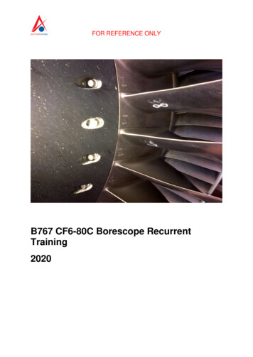
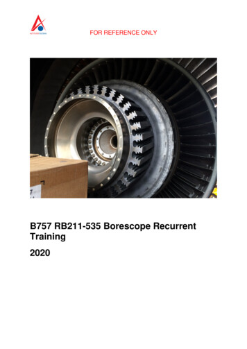
FOR REFERENCE ONLYB757 RB211-535 Borescope RecurrentTraining2020
FOR REFERENCE ONLYIntroductionBorescope inspection is an important practice on anyaircraft. Inspection requirements vary by engine type, andin-service activity. Additionally, an inspection may also becalled when performance has started to lag.Whenever you perform your inspection, a special focusneeds to fall on the engine and techniques required. Amodern jet engine is made to withstand extremecircumstances along with efficient and prolonged use, butthey are still subject to damage and wear. Routineinspection and maintenance can help prevent mostinstances of engine failure and prolong the life of the enginein service. During engine borescope inspection the operatorcan spot issues that indicate future, or imminent failure.During a complete inspection using a borescope, mostissues can be found before they become an issue. Thismodule has been prepared as part of your continuationtraining.Remember to always refer to the correct and currentissue of the AMM prior and during an inspection. Fortraining purposes please study the information from theaircraft maintenance manual attached.
FOR REFERENCE ONLYRB211-535 SERIES ENGINES757AIRCRAFT MAINTENANCE MANUALENGINE - INSPECTION/CHECK1.DHIGeneralA. This procedure has these tasks:DHI 113-120 PRE SB RB211-72-C230NOTE: The limits in this section are applicable to phase II engines only. Phase II engines(ENG3309) have serial numbers below 31720.DHIDHIDHIDHI 101-121, 301-999 PRE SB RB211-72-C230; PHASE II COMBUSTION2.(1)Borescope Equipment Preparation and Use(2)Prepare the Airplane for the Inspection(3)Inspection of the Intermediate Pressure (IP) Compressor(4)Inspection of the High Pressure (HP) Compressor(5)HP Compressor Rotor Path Liners (Stages 1 to 4) Inspection(6)Combustion Liners Inspection(7)High Pressure Nozzle Guide Vanes (HPNGV) Inspection(8)Inspection of the High Pressure (HP) Turbine(9)Intermediate (IP) Turbine Inspection(10)Inspection of the Low Pressure (LP) Turbine(11)Inspection of the 3rd Stage LPT Nozzle Guide Vanes(12)Remove the Borescope Equipment(13)Put the Airplane Back to its Usual ConditionB.It is possible to visually examine the gas generator at different positions with the use of theborescope equipment.C.The inspection equipment is a 110v/240v AC light box.(1)You use this to transmit light along a flexible fiber light cable to the probe viewing instrument.(2)You can use all of the different probe types.(3)This will let you examine the different areas of the gas generator correctly.(4)It is possible for you to get a photograph through the probe eyepiece.D.You can examine the compressor and turbine rotor blades, the internal walls of the combustion linerand the HP nozzle-guide-vanes.E.For the inspections of other areas of the engine not given in this procedure, refer to theseprocedures:(1)LP compressor rotor blades and root dampers(2)LP compressor case(3)Turbine exhaust system.TASK 72-00-00-726-210-R02Borescope Equipment Preparation and Use(Figure 601)NOTE: This procedure is a scheduled maintenance task.72-00-00EFFECTIVITYDHI 101-121, 301-999 PRE SB RB211-72-C230;PHASE II COMBUSTIOND633N189ECCN 9E991 BOEING PROPRIETARY - Copyright Unpublished Work - See title page for detailsConfig 2Page 601Jan 20/2019
FOR REFERENCE ONLYRB211-535 SERIES ENGINES757AIRCRAFT MAINTENANCE MANUALA.General(1)This task provides the instructions on how to prepare and use the borescope equipment.(2)This task lists the inspection equipment, the light-source test and the installation of theborescope equipment used in the engine inspection.(3)Borescope Inspection Equipment (Table 601)Table 601/72-00-00-993-833-R00 EquipmentSupplierPart No.DescriptionItem No. (Figure 601)Rolls-Royce1702322Light source box and case(NDT LSB-05-150) For usewith all borescopes1 and 2Rolls-Royce1017358Light source box (NDT LSB100/ QH) used with 10120948carrying case1 and 2Rolls-Royce1702227Cable - light guide (NDTFLGG/10/15A)3Rolls-Royce1702375Endoprobe (Green) (NDT 8,120, 55, 270)4Rolls-Royce1702379Endoprobe (Blue) (NDT 8,180, 55, 270)5Rolls-Royce1702374Endoprobe (Red) (NDT 8, 90,55 270)6Rolls-Royce1702376Endoprobe (Yellow) (NDT 8,70, 55 270)7Rolls-Royce1702377Endoprobe (Red) (NDT 11, 90,30 265F)14Rolls-Royce1702378Endoprobe (Red) (NDT 11, 90,10 265F)15Rolls-Royce1702368Location Stop (NDT A3101E)use with 1702378-Rolls-Royce1702422Location Stop (NDT 11, 90,55, 185F)-Rolls-Royce1702394Eye Piece (EF/12)13Rolls-Royce1702371Portable light source box (NDTKVB-MK.1) For use with allborescope except 170231910Cable (For use withitem 10)11Rolls-Royce1702393Right angle viewer (NDT2/RA3)12Rolls-Royce1702380Right angle viewer (NDTRAV535)1872-00-00EFFECTIVITYDHI 101-121, 301-999 PRE SB RB211-72-C230;PHASE II COMBUSTIOND633N189ECCN 9E991 BOEING PROPRIETARY - Copyright Unpublished Work - See title page for detailsConfig 2Page 602Jan 20/2019
FOR REFERENCE ONLYRB211-535 SERIES ENGINES757AIRCRAFT MAINTENANCE MANUALTable 601/72-00-00-993-833-R00 Equipment (Continued)SupplierPart No.DescriptionItem No. (Figure 601)Rolls-Royce1702381Carrying Case (NDT CC/3)21Rolls-Royce1702319Flexible BorescopeRolls-RoyceHU19036/1Impact extractorRolls-Royce89200Protective workmat(4)(a)Inspection lamp(b)Clean, stiff bristled brushUse the Consumable Material below table below (Table 602):Table 602/72-00-00-993-834-R00 Consumable RefOMatItem No.Degreaser Fluid Acetone ORB.S.509 1964MIL-D-6998150Isopropyl Alcohol OR1/40Cleaning Solvent Desoclean45 P-D-680TY11/257Jointing compoundDTD.900/4586 PL.32 (light)-4/46High temperature anti-seizecompoundRocol ASC251T-4/62LockwireDTD.189A 22 S.W.G.21 A.W.G.238B.C.ReferencesReference72-00-00 P/B 201TitleENGINE - MAINTENANCE PRACTICESProcedureSUBTASK 72-00-00-846-201-R02(1)Prepare the equipment for the inspection.(a)Make sure the switch at the rear of the light source box [1] is at the correct voltage.(b)Connect the power supply to the light source box.(c)Set the intensity switch to the lowest light position.(d)Do a function check of the light source box.(e)1)Set the power supply to ON and make sure that the red indication light comes on.2)Put the power supply switch back to the OFF position.Attach the light cable [3] to the light source box.NOTE: The flexible borescope has an integral light cable and it is not necessary toattach the light cable (3).(f)If you use the portable light source, attach the cable [11] to the portable light source box[10].NOTE: The portable light source is used with all borescopes, but not 1702319.72-00-00EFFECTIVITYDHI 101-121, 301-999 PRE SB RB211-72-C230;PHASE II COMBUSTIOND633N189ECCN 9E991 BOEING PROPRIETARY - Copyright Unpublished Work - See title page for detailsConfig 2Page 603Jan 20/2019
FOR REFERENCE ONLYRB211-535 SERIES ENGINES757AIRCRAFT MAINTENANCE MANUAL(g)Attach the applicable borescope to the light cable, or attach the flexible borescope to thelight source box.(h)Set the power supply to the ON position.SUBTASK 72-00-00-846-202-R02(2)Do these steps to use the borescope inspection equipment:NOTE: After the removal of the borescope plug, it is possible for the HPNGV support ring heatshield to move on the support ring. There can be axial or circumferential movementand the two are caused by deterioration of the heat shield. This movement can closepart of the borescope port 'G' on the HP turbine. You can position the heat shieldcorrectly with your hands to permit the borescope to be put into the port. The engine issatisfactory with a heat shield that is loose.(a)Put the borescope through the applicable opening for the inspection to be done.(b)Turn the IP or the HP system for the compressor or turbine inspection(PAGEBLOCK 72-00-00/201).(c)Refer to the applicable inspection.1)IP Compressor2)HP Compressor3)Combustion liners and HPNGVa)If the inspection through the fuel spray nozzle aperture, do the steps thatfollow: 1 Do an inspection through the fuel spray nozzle aperture. a Remove the borescope stop adapter, if it is attached.MAKE SURE THE BORESCOPE DOES NOT MOVEFORWARD OF THE HP OUTLET GUIDE VANES. IFYOU DO NOT, THE BORESCOPE WILL HIT THE HPCOMPRESSOR STAGE 6 ROTOR BLADES WHENTHE HP SYSTEM IS TURNED.MAKE SURE THE FLEXIBLE BORESCOPE DOESNOT CATCH THE INTERNAL PARTS OF THECAUTION ENGINE.IF YOU DO NOT DO THIS, DAMAGE TO THEBORESCOPE COULD OCCUR. ALSO, DAMAGE TOTHE POWER PLANT COULD OCCUR IF THEBORESCOPE BECOMES BROKEN INSIDE THEENGINE. b Insert the flexible borescope through the fuel spray nozzleaperture and pass it carefully through the outer diffuser of thecombustion liner head section. Then, pass the borescopebetween the HP outer guide vanes at their inner platform. c Rotate the HP system (PAGEBLOCK 72-00-00/201).72-00-00EFFECTIVITYDHI 101-121, 301-999 PRE SB RB211-72-C230;PHASE II COMBUSTIOND633N189ECCN 9E991 BOEING PROPRIETARY - Copyright Unpublished Work - See title page for detailsConfig 2Page 604Jan 20/2019
FOR REFERENCE ONLYRB211-535 SERIES ENGINES757AIRCRAFT MAINTENANCE MANUALMAKE SURE THE FLEXIBLE BORESCOPE DOESNOT CATCH THE INTERNAL DETAILS OF THEENGINE. IF YOU DO NOT, DAMAGE TO THEBORESCOPE COULD OCCUR. ALSO, DAMAGE TOCAUTION THE POWERPLANT COULD OCCUR IF THEBORESCOPE BECOMES CAUGHT OR BROKENINSIDE THE ENGINE. d (d)4)HP Turbine5)IP Turbine6)LP Turbine.Refer to the HP Compressor inspection given in this procedure.Remove the borescope from the engine after the inspection.SUBTASK 72-00-00-080-005-R00(3)Disassemble the borescope equipment if it is necessary:(a)Select power supply switch to OFF. Let the power supply cool for at least 30 seconds.(b)Remove the borescope and light cable from the light source box.(c)Disconnect the power supply from the light source box.END OF TASK72-00-00EFFECTIVITYDHI 101-121, 301-999 PRE SB RB211-72-C230;PHASE II COMBUSTIOND633N189ECCN 9E991 BOEING PROPRIETARY - Copyright Unpublished Work - See title page for detailsConfig 2Page 605Jan 20/2019
FOR REFERENCE ONLYRB211-535 SERIES ENGINES757AIRCRAFT MAINTENANCE MANUAL1. Light source box2. Carrying case for item 13. Cable-light guide4. Endoprobe (Green)Diameter 0.315 inch (8.0 mm)Length 10.6 inches (270.0 mm)View fore oblique 120 degrees5. Endoprobe (Blue)Diameter 0.315 inch (8.0 mm)Length 10.6 inches (270.0 mm)View forward 180 degrees6. Endoprobe (Red)Diameter 0.315 inch (8.0 mm)Length 10.6 inches (270.0 mm.)View lateral 90 degrees7. Endoprobe (Gold)Diameter 0.315 inch (8.0 mm)Length 10.6 inches (270.0 mm)View retro 70 degrees8. Eyepiece cover for items 4,5,6 and 79. Tip cover for items 4,5,6 and 710. Portable light source box (batteryoperated)11. Cable - for use with item 1012. Right angle viewer13. Eyepiece adapter14. Endoprobe (Red)Diameter 0.433 inch (11.0 mm)Length 10.4 inches (265.0 mm)View lateral 90 degrees15. Endoprobe (Red)Diameter 0.433 inch (11.0 mm)Length 10.4 inches (265.0 mm)View lateral 90 degrees16.17.18.19.20.21.Eyepiece cover for items 14 and 15Tip cover for items 14 and 15Right angle viewerSteady handle for item 18Eyepiece cover for item 18Carrying case277188 S00061280650 V2Borescope Inspection EquipmentFigure 601/72-00-00-990-929-R02 (Sheet 1 of 3)72-00-00EFFECTIVITYDHI 101-121, 301-999 PRE SB RB211-72-C230D633N189ECCN 9E991 BOEING PROPRIETARY - Copyright Unpublished Work - See title page for detailsConfig 2Page 606Jan 20/2019
FOR REFERENCE ONLYRB211-535 SERIES ENGINES757AIRCRAFT MAINTENANCE MANUALENDPROBE COLOR CODE70 GOLD RETROVIEW90 REDLATERALMANUFACTURED BY -INSPECTIONINSTRUMENTS (NDT) LTD3 WOODLAND IND ESTWESTBURYWILTS-ENGLANDTEL 0373 864287120 FORWARDGREEN OBLIQUEBLUE FORWARD180 21171516451486101221913POWER SUPPLYSWITCH793INTENSITY SWITCH181INDICATOR LIGHTPOWER SUPPLY LEADPOWER SUPPLY SWITCH112046967277189 S00061280651 V1Borescope Inspection EquipmentFigure 601/72-00-00-990-929-R02 (Sheet 2 of 3)72-00-00EFFECTIVITYDHI 101-121, 301-999 PRE SB RB211-72-C230D633N189ECCN 9E991 BOEING PROPRIETARY - Copyright Unpublished Work - See title page for detailsConfig 2Page 607Jan 20/2019
FOR REFERENCE ONLYRB211-535 SERIES ENGINES757AIRCRAFT MAINTENANCE CABLE TO LIGHTSOURCE BOXA2787628357 S00061280652 V1Borescope Inspection EquipmentFigure 601/72-00-00-990-929-R02 (Sheet 3 of 3)72-00-00EFFECTIVITYDHI 101-121, 301-999 PRE SB RB211-72-C230D633N189ECCN 9E991 BOEING PROPRIETARY - Copyright Unpublished Work - See title page for detailsConfig 2Page 608Jan 20/2019
FOR REFERENCE ONLYRB211-535 SERIES ENGINES757AIRCRAFT MAINTENANCE MANUAL3.TASK 72-00-00-866-142-R02Engine Inspection Preparation(Figure 602)NOTE: This procedure is a scheduled maintenance task.A.General(1)B.C.This task provides the instructions on how to prepare the engine for the 78-31-00-912-042-R04Location ZonesZone410420D.TitleCompressor Fairing Removal (P/B 401)Open the Thrust Reverser (P/B 201)AreaNo. 1 PowerplantNo. 2 PowerplantEngine Inspection PreparationSUBTASK 72-00-00-860-015-R00(1)For the left engine, open these circuit breakers and install safety tags:Overhead Circuit Breaker Panel, P11RowCol NumberNameD7C01434ENGINES STBY IGN L 1D8C01435ENGINES STBY IGN L 2L1C01430LEFT ENGINE IGN 1SUBTASK 72-00-00-860-016-R00(2)For the right engine, open these circuit breakers and install safety tags:Overhead Circuit Breaker Panel, P11RowCol NumberNameD9C01437ENGINES STBY IGN R 1D10 C01438ENGINES STBY IGN R 2L28 C01432RIGHT ENGINE IGN 1SUBTASK 72-00-00-860-017-R00(3)For the left engine, open this circuit breaker and install safety tag:Overhead Circuit Breaker Panel, P11RowCol NumberNameD19 C01510ENGINES START CONT LSUBTASK 72-00-00-860-018-R00(4)For the right engine, open this circuit breaker and install safety tag:Overhead Circuit Breaker Panel, P11RowCol NumberNameD20 C01511ENGINES START CONT R72-00-00EFFECTIVITYDHI 101-121, 301-999 PRE SB RB211-72-C230;PHASE II COMBUSTIOND633N189ECCN 9E991 BOEING PROPRIETARY - Copyright Unpublished Work - See title page for detailsCo
instances of engine failure and prolong the life of the engine in service. During engine borescope inspection the operator can spot issues that indicate future, or imminent failure. During a complete inspection using a borescope, most issues can be found before they become an issue. This module has been prepared as part of your continuation training.