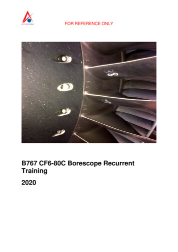
Transcription
CF6-80C2 Airbus Service Bulletins (SBs)SB 72-1577 R01 ENGINE - Fuel Manifold and Drains (72-65-00) - HMU/MEC Idler AdapterInspectionCF6-80C2 SERVICE BULLETIN - 72-1577 R01SB 72-1577 R01 ENGINE - FUEL MANIFOLD AND DRAINS(72-65-00) - HMU/MEC IDLER ADAPTER INSPECTIONRevised:08/16/2019Issued:10/31/2018GE Designated: -CONFIDENTIAL-The information contained in this document is GE proprietaryinformation and is disclosed in confidence. It is the property of GEand shall not be used, disclosed to others or reproduced without theexpress written consent of GE, including, but without limitation, it isnot to be used in the creation, manufacture, development, or derivationof any repairs, modifications, spare parts, designs, or configurationchanges or to obtain FAA or any other government or regulatory approvalto do so. If consent is given for reproduction in whole or in part,this notice and the notice set forth on each page of this documentshall appear in any such reproduction in whole or part.This technical data is considered subject to the Export AdministrationRegulations (EAR) pursuant to 15 CFR Parts 730-774. Transfer of thisdata by any means to a Non-U.S. Person, whether in the United States orabroad, without the proper U.S. Government authorization (e.g.,License, exemption, NLR, etc.), is strictly prohibited.Copyright (2019) General Electric Company, U.S.A.TRANSMITTAL INFORMATIONREVISION 1 TO SERVICE BULLETIN 72-1577Revision 1 is issued to update paragraphs 1., PLANNING INFORMATION, 2.,MATERIAL INFORMATION, and 3., ACCOMPLISHMENT INSTRUCTIONS.The original was issued October 31, 2018. Revision bars in the leftmargin identify changes.1. PLANNING INFORMATIONA. Effectivity* * * CF6-80C2A1/A2/A3/A5/A8/B1/B2/B4/B6* * * is Service Bulletin is not applicable to these CF6-80C2engines:* CF6-80C2 engines, serial numbers 707-417 and up are not affected by thisService Bulletin.* CF6-80C2 engines, which have not had a shop visit prior to November 1, 2018.These serial numbers are the best available data.The accessory gearbox (AGB) adapters [hydromechanical unit(HMU)/main engine control (MEC) idler adapters] P/N 9395M78G01,P/N 9395M78G02, P/N 9395M78G04, P/N 9395M78G05, P/N 9395M78G08,and P/N 9395M78G10 are affected by this Service Bulletin.GE PROPRIETARY INFORMATION - Not to be used, disclosed toDate Printed: others or reproduced without the express written consent ofGE. Technical data is considered ITAR and/or EAR controlled;2019/09/18transfer of this data to a Non-US Person, without USGauthorization, is strictly prohibited.Page1 of 13
CF6-80C2 Airbus Service Bulletins (SBs)SB 72-1577 R01 ENGINE - Fuel Manifold and Drains (72-65-00) - HMU/MEC Idler AdapterInspectionThis Service Bulletin is applicable only for AGB adapters withTap-Lok inserts.B. DescriptionThis Service Bulletin provides instructions to do an inspectionof the inserts on the HMU/MEC idler adapter and a pull check.C. ComplianceCategory 2GE recommends that you do this Service Bulletin as soon aspossible without effect on revenue service but no later than1,200 flight hours from Service Bulletin issuance date withrepeat inspections not to exceed 1,200 flight hours betweeninspections. Terminating action to be completed no later thannext shop visit.Impact BThis recommendation is to address a condition that may result inan Increased Rate of In-Flight Shutdowns (IFSD), Take-Off Aborts(TOA), Air Turn Backs (ATB) or Diversions (DIV).NOTE: This Service Bulletin can be done on wing or in shop.This Service Bulletin is offered to improve the reliability orperformance of your GE product, or to help prevent the occurrenceof the event or condition described in this Service Bulletin. Ifthe operator elects not to participate in the bulletin, thatdecision will be taken into consideration by GE in evaluatingfuture product performance issues that may arise in theoperator's fleet.D. Concurrent RequirementsNone.E. Reason(1) Objective:To improve reliability and reduce significant events.To prevent a fuel leak and possible undercowl fire events in the CF6-80C2engines.(2) Condition:A threaded insert in the HMU/MEC idler adapter flange pulled-out, causing afuel leak.(3) Cause:The repair of the insert was done incorrectly.(4) Inspection:The inspection will detect if the inserts are installed correctly.(5) Substantiation:Substantiation is by comparative analysis and fleet experience.F. ApprovalThis Service Bulletin contains no modification information thatrevises the approved configuration and therefore does not requireFAA or regulatory approval.G. ManpowerAfter you get access to the AGB assembly, you will need 1man-hour to do the shim check. If the assembly passes the shimcheck, no additional manpower is required. If the assembly failsthe shim check, 4 additional man-hours will be needed to do theprotrusion and pull-out test of the inserts.H. Weight and BalanceWeight and balance are not changed.GE PROPRIETARY INFORMATION - Not to be used, disclosed toDate Printed: others or reproduced without the express written consent ofGE. Technical data is considered ITAR and/or EAR controlled;2019/09/18transfer of this data to a Non-US Person, without USGauthorization, is strictly prohibited.Page2 of 13
CF6-80C2 Airbus Service Bulletins (SBs)SB 72-1577 R01 ENGINE - Fuel Manifold and Drains (72-65-00) - HMU/MEC Idler AdapterInspectionI. References (Use the latest version of these documents)Airbus A300-600 Aircraft Maintenance Manual (AMM)Airbus A310 Aircraft Maintenance Manual (AMM)Boeing 747-200/300 Aircraft Maintenance Manual (AMM)Boeing 747-400 Aircraft Maintenance Manual (AMM)Boeing 767 Aircraft Maintenance Manual (AMM)McDonnell Douglas MD-11 Aircraft Maintenance Manual (AMM)GEK 9250, Commercial Engine Standard Practices Manual (SPM)GEK 92451, CF6-80C2 Engine Manual (EM)GEK 92452-1, CF6-80C2A (PMC) Illustrated Parts Catalog (IPC)GEK 92452-2, CF6-80C2B (PMC) Illustrated Parts Catalog (IPC)GEK 92452-3, CF6-80C2D (FADEC) Illustrated Parts Catalog (IPC)GEK 92452-4, CF6-80C2B (FADEC) Illustrated Parts Catalog (IPC)GEK 92452-5, CF6-80C2A (FADEC) Illustrated Parts Catalog (IPC)J. Publications AffectedNone.K. InterchangeabilityNot applicable.L. Software Accomplishment SummaryNot applicable.2. MATERIAL INFORMATIONA. Material - Price and Availability(1) Parts necessary to do this Service Bulletin:None.(2) Other Spare Parts:Qty/Part NumberEngPart NameUnit ( )PricePkgQtyLead TimeDays1453M60P04(AR)Gasket, Seal28.00(10)59117M58P07(AR)Insert, Oversize50.25Screw P08(AR)Insert, Oversize72.50(10)5Screw (ThirdOversize)Thread-Self-TappingNOTE: Prices are provided for planning purposes and are subject to change.(3) Consumables:Code NumberDescriptionC03-001Primer, Zinc ChromateC04-035Solvent, General (isopropyl alcohol)C10-067Tape, Platers (tape) (or equivalent)C10-182Cloth, Cleaning for Aircraft Structural (clean cloth)B. Industry Support InformationNone.C. Configuration ChartNone.D. Parts DispositionRemove and replace inserts if a failure of the pull-out testoccurs.GE PROPRIETARY INFORMATION - Not to be used, disclosed toDate Printed: others or reproduced without the express written consent ofGE. Technical data is considered ITAR and/or EAR controlled;2019/09/18transfer of this data to a Non-US Person, without USGauthorization, is strictly prohibited.Page3 of 13
CF6-80C2 Airbus Service Bulletins (SBs)SB 72-1577 R01 ENGINE - Fuel Manifold and Drains (72-65-00) - HMU/MEC Idler AdapterInspectionE. Tooling - Price and AvailabilityDescriptionRefer ToLocally Manufactured Pull-OutTest ToolFigure 2Tool NumberDescription--Screw Extractor [for use in a 0.250 inch (6.35 mm)hole]--High Speed Hand Drill--Appropriate Size Uncoated, Straight Flute or TwistDrill Bit with a Point Angle of 115 to 140 Degrees--1/4-28 Tap-Lok Insertion Driver Tool3. ACCOMPLISHMENT INSTRUCTIONSA. GeneralNOTE: This Service Bulletin contains two options.(1) Option 1 - repetitive shim check, to be performed within 1,200 flight hourswith repeat inspections not to exceed 1,200 flight hours betweeninspections. Refer to paragraph 3.B., Option 1 - Containment Action.(2) Option 2 - one-time pull check of the installed inserts on the HMU/MECidler adapter to be performed no later than next engine shop visit. Referto paragraph 3.C., Option 2 - Terminating Action.B. Option 1 - Containment Action(1) Do a shim check at the eight bolt locations as follows:NOTE: Removal of the bracket is optional. The shim check can be done with andwithout the bracket installed.(a) Optional Procedure. Remove the bracket. Refer to Figure 1, Item 3(Bolt) and Item 4 (Bracket).1Remove the three bolts that attach the bracket.2Remove the bracket.3Install the bolts again and torque the bolts to 110 to 140 lb in.(12.4 to 15.8 Nm).(b) Do the shim check with a shim stock of 0.004 inch (0.10 mm) on theadapter flange-gasket interface. Refer to Figure 1 and do as follows:1Insert a shim of 0.004 inch (0.10 mm) between the gasket and theHMU/MEC idler adapter flange at each of the eight bolt locations andas follows:aIf you cannot insert the shim of 0.004 inch (0.10 mm) betweenthe gasket and the flange for each of the eight bolt locations,this is considered a PASS.1) Install the bracket back if you removed it. The installationof the bracket, as specified in step 3.B.(1)(b)1b, isnecessary to complete this inspection.bInstall the bracket again. Refer to Figure 1, Item 3 (Bolt) andItem 4 (Bracket) and do as follows:1) Remove the three bolts at the bracket location.2) Install the bracket with the three bolts.3) Torque the three bolts to 110 to 140 lb in. (12.4 to 15.8Nm).cIf you can insert the shim of 0.004 inch (0.10 mm) between thegasket and the flange at any of the eight bolt locations morethan 0.100 inch (2.54 mm) in depth, this is considered a FAIL.Complete the shim check at each of the remaining bolt locations.Note locations which fail and continue with step 3.B.(1)(c).(c) If the shim check fails, torque the bolt again to 110 to 140 lb in.(12.4 to 15.8 Nm) at each bolt locations that failed the shim check. Dothe shim check again with a shim of 0.004 inch (0.10 mm) on the adapterflange-gasket interface.(d) If the shim check fails once more after you torque the bolt again, doGE PROPRIETARY INFORMATION - Not to be used, disclosed toDate Printed: others or reproduced without the express written consent ofGE. Technical data is considered ITAR and/or EAR controlled;2019/09/18transfer of this data to a Non-US Person, without USGauthorization, is strictly prohibited.Page4 of 13
CF6-80C2 Airbus Service Bulletins (SBs)SB 72-1577 R01 ENGINE - Fuel Manifold and Drains (72-65-00) - HMU/MEC Idler AdapterInspectionparagraph 3.C., Option 2 - Terminating Action.C. Option 2 - Terminating Action(1) Remove the fuel pump tube and fuel tube. Refer to Figure 1, Item 1 (FuelPump Tube) and Item 2 (Fuel Tube) and Table 1 for applicable AMM removalinstructions.NOTE: The rigid fuel pump tube and fuel tube that are installed in the HMU/MECidler adapter pads are connected to the fuel pump (bypass and discharge).The fuel pump tube and fuel tube must be removed from the two sides toget access to the AGB pads.Table 1. Fuel Pump Tube, Fuel Tube Removal, and Installation ReferenceTableAMMProcedureReferenceBoeing747-400 AMM(FADEC)1. Remove the bypass tube form thehydromechanical unit (HMU) adapter on theAGB and remove the discharge tube from theHMU adapter on the AGB.Refer to the Boeing 747-400AMM, 73-11-01, 00,paragraphs (2)(b) and(2)(c).2. Install the bypass tube in the HMUadapter on the AGB and install thedischarge tube in the HMU adapter on theAGB.Refer to the Boeing 747-400AMM, 73-11-01, J00,73-11-01-224-041-J00, . Remove the bypass tube from the mainRefer to the Boeingengine control (MEC) adapter on the AGB and 747-200/300 AMM, 73-11-01,remove the discharge tube from the MECparagraphs 4.C.(3) and (4).adapter on the AGB.2. Install the bypass tube in the MECadapter on the AGB and install thedischarge tube in the MEC adapter on theAGB.Boeing 767AMM(PMC)1. Remove the bypass tube from the MECRefer to the Boeing 767 AMM,adapter on the AGB and remove the discharge 73-11-01, TASKtube from the MEC adapter on the 00,paragraphs (2)(b) and(2)(c).2. Install the bypass tube in the MECadapter on the AGB and install thedischarge tube in the MEC adapter on theAGB.Boeing 767AMM(FADEC)Refer to the Boeing747-200/300 AMM, 73-11-01,paragraphs J.(1), (2), and(3).Refer to the Boeing 767 AMM,73-11-01, H00,73-11-01-224-028-H00, and73-11-01-434-029-H00.1. Remove the bypass tube from the HMURefer to the Boeing 767 AMM,adapter on the AGB and remove the discharge 73-11-01, TASKtube from the HMU adapter on the 03,paragraphs (2)(c) and(2)(d).2. Install the bypass tube in the HMUadapter on the AGB and install thedischarge tube in the HMU adapter on theAGB.Refer to the Boeing 767 AMM,73-11-01, TASK73-11-01-404-018-H03,SubtasksGE PROPRIETARY INFORMATION - Not to be used, disclosed toDate Printed: others or reproduced without the express written consent ofGE. Technical data is considered ITAR and/or EAR controlled;2019/09/18transfer of this data to a Non-US Person, without USGauthorization, is strictly prohibited.Page5 of 13
CF6-80C2 Airbus Service Bulletins (SBs)SB 72-1577 R01 ENGINE - Fuel Manifold and Drains (72-65-00) - HMU/MEC Idler -029-H03, and73-11-01-434-032-H03.McDonnellDouglasMD-11 AMM(FADEC)AirbusA300-600(FADEC)1. Remove the return fuel tube and thecontrol fuel tube from the fuel pump andthe AGB.Refer to the McDonnellDouglas MD-11 AMM, 73-12-01,TASK 73-12-01-000-801,Subtask 73-12-01-030-001.2. Install the return fuel t
GE recommends that you do this Service Bulletin as soon as possible without effect on revenue service but no later than 1,200 flight hours from Service Bulletin issuance date with repeat inspections not to exceed 1,200 flight hours between inspections. Terminating action to be completed no later than next shop visit. Impact B This recommendation is to address a condition that may result in an .