Transcription
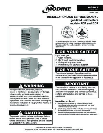
6-580.45H78213A Rev. EOctober, 2008installation and service manualgas-fired unit heatersmodels PDP and BDPAll models approved for use in California by the CEC (whenequipped with IPI), in New York by the MEA division, and inMassachusetts. Unit heater is certified for non-residentialapplications.FOR YOUR SAFETYIf you smell gas:1. Open windows.2. Don’t touch electrical switches.3. Extinguish any open flame.4. Immediately call your gas supplier.FOR YOUR SAFETYThe use and storage of gasoline or otherflammable vapors and liquids in open containersin the vicinity of this appliance is hazardous.WARNINGImproper installation, adjustment, alteration,service or maintenance can cause property damage,injury or death, and could cause exposure tosubstances which have been determined by variousstate agencies to cause cancer, birth defects or otherreproductive harm. Read the installation, operating andmaintenance instructions thoroughly before installing orservicing this equipment.IMPORTANTThe use of this manual is specifically intendedfor a qualified installation and service agency.A qualified installation and service agency mustperform all installation and service of theseappliances.Inspection on Arrival1.2.CAUTION3.Inspect unit upon arrival. In case of damage, reportimmediately to transportation company and your localModine sales representative.Check rating plate on unit to verify that power supply meetsavailable electric power at the point of installation.Inspect unit received for conformance with description ofproduct ordered (including specifications where applicable).To prevent premature heat exchanger failuredo not locate ANY gas-fired units in areaswhere chlorinated, halogenated, or acid vaporsare present in the atmosphere.THIS MANUAL IS THE PROPERTY OF THE OWNER.PLEASE BE SURE TO LEAVE IT WITH the owner WHEN YOU LEAVE THE JOB.
special precautions / table of contentsSpecial PrecautionsTHE INSTALLATION AND MAINTENANCE INSTRUCTIONSIN THIS MANUAL MUST BE FOLLOWED TO PROVIDESAFE, EFFICIENT AND TROUBLE-FREE OPERATION.iN ADDITION, PARTICULAR CARE MUST BE EXERCISEDREGARDING THE SPECIAL PRECAUTIONS LISTED BELOW.FAILURE TO PROPERLY ADDRESS THESE CRITICALAREAS COULD RESULT IN PROPERTY DAMAGE OR LOSS,PERSONAL INJURY, OR DEATH. THESE INSTRUCTIONSARE SUBJECT TO ANY MORE RESTRICTIVE LOCAL ORNATIONAL CODES.caution1. Purging of air from gas supply line should be performedas described in ANSI Z223.1 - latest edition “National FuelGas Code”, or in Canada in CAN/CGA-B149 codes.2. Do not attempt to reuse any mechanical or electronicignition controllers which has been wet. Replace defectivecontroller.3. Ensure that the supply voltage to the appliance, asindicated on the serial plate, is not 5% less than the ratedvoltage.HAZARD INTENSITY LEVELSimportant1. DANGER: Indicates an imminently hazardous situationwhich, if not avoided, WILL result in death or serious injury.2. WARNING: Indicates a potentially hazardous situation which,if not avoided, COULD result in death or serious injury.3. CAUTION: Indicates a potentially hazardous situation which,if not avoided, MAY result in minor or moderate injury.4. Important: Indicates a situation which, if not avoided,MAY result in a potential safety concern.dangerAppliances must not be installed where they may be exposedto a potentially explosive or flammable atmosphere.warning1. Gas fired heating equipment must be vented - do notoperate unvented.2. A built-in power exhauster is provided - additional externalpower exhausters are not required or permitted.3. All field gas piping must be pressure/leak tested prior tooperation. Never use an open flame. Use a soap solution orequivalent for testing.4. Gas pressure to appliance controls must never exceed 14"W.C. (1/2 psi).5. Disconnect power supply before making wiring connectionsto prevent electrical shock and equipment damage.6. All appliances must be wired strictly in accordance withwiring diagram furnished with the appliance. Any wiringdifferent from the wiring diagram could result in a hazardto persons and property.7. Any original factory wiring that requires replacementmust be replaced with wiring material having atemperature rating of at least 105 C.8. When servicing or repairing this equipment, use onlyfactory-approved service replacement parts. A completereplacement parts list may be obtained by contactingModine Manufacturing Company. Refer to the ratingplate on the appliance for complete appliance modelnumber, serial number, and company address. Anysubstitution of parts or controls not approved by thefactory will be at the owners risk.9. To reduce the opportunity for condensation, the minimumsea level input to the appliance, as indicated on theserial plate, must not be less than 5% below the ratedinput, or 5% below the minimum rated input of dual ratedunits.10. Ensure that the supply voltage to the appliance, asindicated on the serial plate, is not 5% greater than therated voltage. 1. To prevent premature heat exchanger failure, do notlocate ANY gas-fired appliances in areas where corrosivevapors (i.e. chlorinated, halogenated or acid) are presentin the atmosphere.2. Do not attempt to attach ductwork of any kind to propellermodels.3. To prevent premature heat exchanger failure, observeheat exchanger tubes. If the bottom of the tubes becomered while blower and furnace are in operation, checkto be sure the blower has been set to the proper rpmfor the application. Refer to page 9 for Blower Adjustments.4. Start-up and adjustment procedures should be performedby a qualified service agency.5. To check most of the Possible Remedies in the trouble shooting guide listed in Table 25.1, refer to the applicablesections of the manual.6. To prevent premature heat exchanger failure, the input tothe appliance, as indicated on the serial plate, must notexceed the rated input by more than 5%.Table of ContentsInspection on Arrival . . . . . . . . . . . . . . . . . . . . . . . . . . . . . . . . . 1Special Precautions . . . . . . . . . . . . . . . . . . . . . . . . . . . . . . . . . . 2SI (Metric) Conversion Factors . . . . . . . . . . . . . . . . . . . . . . . . . 3Unit Location . . . . . . . . . . . . . . . . . . . . . . . . . . . . . . . . . . . . . . . 3Combustible Material and Service Clearances . . . . . . . . . 3Combustion Air Requirements . . . . . . . . . . . . . . . . . . . . . . 3Unit Lifting and Unit Mounting . . . . . . . . . . . . . . . . . . . . . . 4Installation . . . . . . . . . . . . . . . . . . . . . . . . . . . . . . . . . . . . . . . . . 4Venting . . . . . . . . . . . . . . . . . . . . . . . . . . . . . . . . . . . . . . . . 4Gas Connections . . . . . . . . . . . . . . . . . . . . . . . . . . . . . . . 7Electrical Connections . . . . . . . . . . . . . . . . . . . . . . . . . . . 8Duct Installation . . . . . . . . . . . . . . . . . . . . . . . . . . . . . . . . . 8Blower Installation . . . . . . . . . . . . . . . . . . . . . . . . . . . . . . 8Blower Adjustment . . . . . . . . . . . . . . . . . . . . . . . . . . . . . . . 9Start-Up Procedure . . . . . . . . . . . . . . . . . . . . . . . . . . . . . . . . 10Pilot Burner Adjustment . . . . . . . . . . . . . . . . . . . . . . . . . 10Main Burner Adjustment . . . . . . . . . . . . . . . . . . . . . . . . . . 10Control Operating Sequence . . . . . . . . . . . . . . . . . . . . . 12Options . . . . . . . . . . . . . . . . . . . . . . . . . . . . . . . . . . . . . . . . . 13General Performance Data . . . . . . . . . . . . . . . . . . . . . . . . . . 15Performance Data Nozzles/Hoods . . . . . . . . . . . . . . . . . . . . 19Dimensions Unit . . . . . . . . . . . . . . . . . . . . . . . . . . . . . . . . . . 22Maintenance . . . . . . . . . . . . . . . . . . . . . . . . . . . . . . . . . . . . . 24Service & Troubleshooting . . . . . . . . . . . . . . . . . . . . . . . . . . 25Model Nomenclature/Serial Plate . . . . . . . . . . . . . . . . . . . . . . 27Commercial Warranty . . . . . . . . . . . . . . . . . . . . . . . Back Page6-580.4
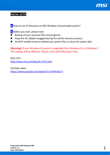
si (metric) conversion factors / unit locationTable 3.1 - SI (Metric) Conversion FactorsTo Convert Multiply By To Obtain"W.C.0.24kPapsig6.893kPa F( F-32) x 0.555 Cinches25.4mmfeet0.305metersCFM0.028m3/minTo Convert Multiply By To 11. In aircraft hangars, keep the bottom of the unit at least 10feet from the highest surface of the wings or engineenclosure of the highest aircraft housed in the hangarand in accordance with the requirements of the enforcingauthority and/or NFPA No. 409 - Latest Edition.Figure 3.1 - Combustible Material and Service ClearancesCUnit LocationdangerAppliances must not be installed where they may be exposedto a potentially explosive or flammable atmosphere.importantTo prevent premature heat exchanger failure, do not locateANY gas-fired appliances in areas where corrosive vapors (i.e.chlorinated, halogenated or acid) are present in the atmosphere.AccessSideBADLocation RecommendationsTable 3.2 - Combustible Material Clearances ➀1. When locating the furnace, consider general space andheating requirements, availability of gas and electricalsupply, and proximity to vent locations.Access Non-Access Top of PowerModel Side Side Top Bottom ExhausterSize(A)(B)(C)(D)(Not shown)150-1751141222. Avoid installing units in extremely drafty locations. Draftscan cause burner flames to impinge on heat exchangers200-400115123which shortens life. Maintain separation between units so➀ Provide sufficient room around the heater to allow for properdischarge from one unit will not be directed into the inletcombustion and operation of fan. Free area around the heater mustof another.not be less than 1-1/2 times the discharge area of the unit.3. Be sure the structural support at the unit location site isadequate to support the weight of the unit. For properTable 3.3 - Recommended Service Clearancesoperation the unit must be installed in a level horizontalposition.Access Non-Access Top of Power4. Do not install units in locations where the flue products canModel Side Side Top Bottom ExhausterSize(A)(B)(C)(D)(Not shown)be drawn into the adjacent building openings such aswindows, fresh air intakes, etc.150-175181862215. Be sure that the minimum clearances to combustible200-40018186251materials and recommended service clearances aremaintained. Units are designed for installation on non-Combustion Air Requirementscombustible surfaces with the minimum clearances shownUnits installed in tightly sealed buildings or confined spacesin Figure 3.1 and Tables 3.2 and 3.3.must be provided with two permanent openings, one near the6. Units exposed to inlet air temperatures of 40 F or less,top of the confined space and one near the bottom. Eachmay experience condensation, therefore, provisions shouldopening should have a free area of not less than one squarebe made for disposal of condensate.inch per 1,000 BTU per hour of the total input rating off all units7. When locating units, it is important to consider that thein the enclosure, freely communicating with interior areasexhaust vent piping must be connected to the outsidehaving, in turn adequate infiltration from the outside.atmosphere.For further details on supplying combustion air to a confined8. In garages or other sections of aircraft hangars such as(tightly sealed) space or unconfined space, see the Nationaloffices and shops that communicate with areas used forFuel Gas Code ANSI Z223.1 of CAN/CGA B149.1 or .2servicing or storage, keep the bottom of the unit at leastInstallation Code, latest edition.7 feet above the floor unless the unit is properly guardedto provide user protection from moving parts. In parkingSound and Vibration Levelsgarages, the unit must be installed in accordance with theAll standard mechanical equipment generates some sound andstandard for parking structures ANSI/NFPA 88A, and invibration that may require attenuation. Libraries, private officesrepair garages the standard for repair garages NFPA #88B.and hospital facilities will require more attenuation, and in suchIn Canada, installation of heaters in airplane hangars mustcases, an acoustical consultant may be retained to assist in thebe in accordance with the requirements of the enforcingapplication. Locating the equipment away from the critical areaauthority, and in public garages in accordance with theis desirable within ducting limitations. Generally, a unit shouldcurrent CAN/CGA-B149 codes.be located within 15 feet of a primary support beam. Smaller9. Do not install units in locations where gas ignition systemdeflections typically result in reduced vibration and noiseis exposed to water spray, rain, or dripping water.transmission.10. Do not install units below 7 feet, measured from the bottomof the unit to the floor, unless properly guarded to provideprotection from moving parts. 6-580.4
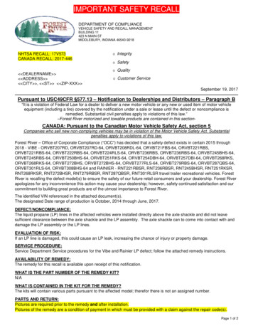
INSTALLATIONUnit liftingFigure 4.1 - Adjustable Mounting Brackets - To Adjust:All units are shipped fully boxed. Larger units are also suppliedwith skid supports on the bottom of the box. The larger unitsmay be lifted from the bottom by means of a fork lift or otherlifting device only if the shipping support skids are left in placeand the forks support the whole depth of the unit. If the unitmust be lifted from the bottom for final installation without thecarton in place, be sure to properly support the unit over itsentire length and width to prevent damage. When lifting units,make sure the load is balanced.1. Remove outer side panels.2. “Set screws” - loosen andposition bracket where needed– then tighten set screws.3. Re-attach outer side panels.Unit suspensionBe sure the method of unit suspension is adequate to supportthe weight of the unit (see Weights for base unit and factoryinstalled option weights). For proper operation, the unit must beinstalled in a level horizontal position. Combustible material andservice clearances as specified in Figure 3.1 and Tables 3.2and 3.3 must be strictly maintained. To assure that flames aredirected into the center of the heat exchanger tubes, the unitmust be level in a horizontal position. Use a spirit level toensure that the unit is suspended correctly.The most common method of suspending Modine gas unitheaters is to utilize 3/8” threaded rod. On each piece ofthreaded rod used, screw a nut a distance of about one inchonto the end of the threaded rods that will be screwed into theunit heater. Then place a washer over the end of the threadedrod and screw the threaded rod into the unit heater weld nutson the top of the heater at least 5 turns, and no more than 10turns. Tighten the nut first installed onto the threaded rod toprevent the rod from turning. Drill holes into a steel channel orangle iron at the same centerline dimensions as the heater thatis being installed. The steel channels or angle iron pieces needto span and be fastened to appropriate structural members. Cutthe threaded rods to the preferred length, place them throughthe holes in the steel channel or angle iron and secure withwashers and lock nuts or lock washers and nuts. A double nutarrangement can be used here instead of at the unit heater (adouble nut can be used both places but is not necessary). Donot install standard unit heaters above the maximum mountingheight shown in Tables 15.1 or 15.3.On all propeller units, except sizes 350 and 400, two tappedholes (3/8-16) are located in the top of the unit to receivethreaded rods.Propeller sizes 150 through 300 units without deflector hoodsthat do not hang level after being installed, can be corrected inplace. Simply remove both outer side panels (screws to removeare on back flange of side panel) and you will see the(adjustable) mounting brackets (Fig. 4.1). Loosen the setscrews holding the mounting brackets in place and using arubber mallet or similar, tap the heater into a position where theunit hangs level. Re-tighten set screws and replace the outerside panels. Figure 4.2 - Suspension MethodsVentingWARNING1. Gas fired heating equipment must be vented - do notoperate unvented.Units with two point suspension, sizes 150 through 300,incorporate a level hanging feature. Depending on what optionsand accessories are being used, the heater may not hang levelas received from the factory. Do not hang heaters with deflectorhoods until referring to the “installation manual for deflectorhoods” and making the recommended preliminary adjustmentson the heater. These preliminary adjustments need to be madewith the heater resting on the floor.Propeller sizes 350 and 400 have four mounting holes. Onall blower units, except the 350 and 400, two tapped holesare provided in the top of the unit and two holes in the blowersupport bracket. The 350 and 400 have four tapped holes inthe top of the unit and two in the blower support bracket formounting.A pipe hanger adapter kit, shown in Figure 4.2 is available asan accessory. One kit consists of two drilled 3/4” IPS pipe capsand two 3/8 - 13 x 1-3/4” capscrews to facilitate threaded pipesuspension.2. A built-in power exhauster is provided - additionalexternal power exhausters are not required or permitted.NOTE: A vent is the vertical passageway used to conveyflue gases from the unit or the vent connector to the outsideatmosphere. A vent connector is the pipe which connects theunit to a vent or chimney. Vent connectors serving CategoryI appliances shall not be connected into any portion ofmechanical draft systems operating under positive pressure.General Venting Air Instructions1. Installation of venting must conform with local buildingcodes, or in the absence of local codes, with the NationalFuel Gas Code, ANSI Z223.1 (NFPA 54) - Latest Edition.In Canada, installation must be in accordance with CAN/CGA-B149.1 for natural gas units and CAN/CGA-B149.2 forpropane units.2. All vertically vented units are Category I. All horizontallyvented units are category III. The installation must conformto the requirements from Table 5.1 in addition to those listedbelow.3. From Table 22.1 or 23.1, select the size of vent pipe that fitsthe flue outlet for the unit. Do not use a vent pipe smallerthan the size of the outlet or vent transition of the appliance.The pipe should be suitable corrosion resistant material.Follow the National Fuel Gas Code for minimum thicknessand composition of vent material. The minimum thickness forconnectors varies depending on the pipe diameter.6-580.4
installation4. For Category I vent systems limit length of horizontal runs to75% of vertical height. Install with a minimum upward slopefrom unit of 1/4 inch per foot and suspend securely fromoverhead structure at points no greater than 3 feet apart.For best venting, put vertical vent as close to the unit aspossible. A minimum of 12' straight pipe is recommendedfrom the power exhauster outlet before turns in the ventsystem. Fasten individual lengths of vent together with atleast three corrosion-resistant sheet-metal screws.5. It is recommended that vent pipes be fitted with a tee witha drip leg and a clean out cap to prevent any moisture in thevent pipe from entering the unit. The drip leg should beinspected and cleaned out periodically during the heatingseason.6. The National Fuel Gas Code requires a minimum clearanceof 6 inches from combustible materials for single wall ventpipe. The minimum distance from combustible materials isbased on the combustible material surface not exceeding160 F. Clearance from the vent pipe (or the top of the unit)may be required to be greater than 6 inches if heat damageother than fire (such as material distortion or discoloration)could result.13. For instructions on common venting refer to the NationalFuel Gas Code.14. The vent must terminate no less than 5' above the ventconnector for category I vent systems.15. A unit located within an unoccupied attic or concealed spaceshall not be vented with single wall vent pipe.16. Single wall vent pipe must not pass through
Massachusetts. Unit heater is certified for non-residential applications. inspection on arrival. 1. Inspect unit upon arrival. In case of damage, report immediately to transportation company and your local Modine sales representative. 2. Check rating plate on unit to verify that power su