Transcription
403 Poyntz Avenue, Suite BManhattan, KS 66502USA 1.785.770.8511www.thunderheadeng.comTMVOC Buckley-Leverett FlowPetraSim 2016.1
Table of Contents1. Buckley-Leverett Flow .1Description . 1Create a New Model . 1Default Units . 1Save the Model . 2Specify the Solution Mesh . 2Global Properties . 2Edit VOC Data . 2Change CHEMP.6 Data . 3Change CHEMP.7 Data . 3Change CHEMP.8 Data . 3Change CHEMP.9 Data . 4Add to Active VOC List . 4Material Properties . 4Define Additional Material Data . 5Initial Conditions . 5Edit Mesh . 5Solution Controls. 7Output Controls . 8Save and Run. 8View Results . 8View Cell Time History Plots . 9ii
DisclaimerThunderhead Engineering makes no warranty, expressed or implied, to users of PetraSim, and acceptsno responsibility for its use. Users of PetraSim assume sole responsibility under Federal law fordetermining the appropriateness of its use in any particular application; for any conclusions drawn fromthe results of its use; and for any actions taken or not taken as a result of analyses performed usingthese tools.Users are warned that PetraSim is intended for use only by those competent in the field of multi-phase,multi-component fluid flow in porous and fractured media. PetraSim is intended only to supplement theinformed judgment of the qualified user. The software package is a computer model that may or maynot have predictive capability when applied to a specific set of factual circumstances. Lack of accuratepredictions by the model could lead to erroneous conclusions. All results should be evaluated by aninformed user.Throughout this document, the mention of computer hardware or commercial software does notconstitute endorsement by Thunderhead Engineering, nor does it indicate that the products arenecessarily those best suited for the intended purpose.iii
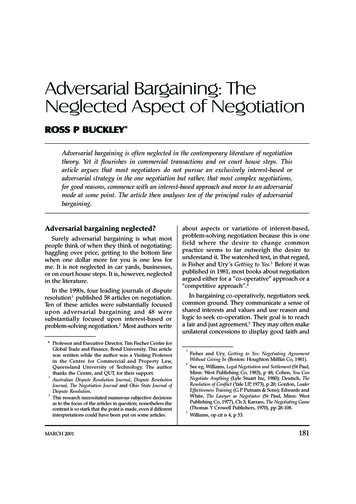
1. Buckley-Leverett FlowDescriptionThis example is Problem No. 2 (*rblm*) - "1-D Buckley-Leverett Flow" - as described in "TMVOC, ANumerical Simulator for Three-Phase Non-Isothermal Flows of Multicomponent Hydrocarbon Mixturesin Saturated-Unsaturated Heterogeneous Media", Pruess and Battistelli, LBNL-49375, 2002.The geometry of the problem is given below. A horizontal column, 304.8 m long is divided into 40elements. The column is filled with an initial mixture of NAPL and water. Water is injected at one endand, at the other end, a single cell is used to define a constant boundary condition.Figure 1.1: Problem geometryCreate a New Model1.2.3.4.On the File menu, click New.For both the Simulator Mode and EOS choose TMVOC.For the Model Bounds enter the coordinates as shown in Table 1.1.Click OK.Table 1.1: Model boundsAxisXYZMin (m)0.00.0-1.0Max (m)304.81.00.0Default UnitsBy default, PetraSim uses the TOUGH2 metric unit system (for example, the TOUGH2 system specifiespermeability in units of m2). We will use the default system. To change the default units:1. On the View menu, click Unit System.2. Select the units you wish to use for each parameter.1
Note that even if using the default TOUGH2 system, you can enter values in any of the optional unitssupported by PetraSim. For example, you can type 10 years for time or 5 mD for permeability. PetraSimwill convert to the units being used in the model.Save the ModelIt is good practice to save the model initially. Some of the files created by TOUGH have the same namefor every simulation, so it is good practice to create a separate folder for simulation.To save your model:1. On the File menu, click Save.2. Create a new folder named TMVOC Prob 2 and in the File Name box, type TMVOC prob2.3. Click Save.Specify the Solution MeshFor this simulation, we only want one cell in the (Z) direction. This is the default value, so we do notneed to edit this value in the layers. However, we do need to define the mesh in the X and Y directions:1.2.3.4.On the Model menu, click Create Mesh.In the X Cells box, type 40.In the Y Cells box, type 1.Click OK to create the mesh.Global Properties1.2.3.4.5.6.7.On the Properties menu, click Global Properties.In the Name box, type TMVOC Problem 2.Click the EOS TAB.Select the Isothermal Mode check box.Click the Edit Options button to edit thermophysical options.In the Air Solubility Correlation list, select KH 1010(Pa) Independent of Temperature.Click OK to close the Thermophysical Properties dialog.Edit VOC DataThe VOC (NAPL) used in this example is not chemically active, so it is necessary to create a new VOC withsome modifications. Note: When you create a new VOC, the data is saved to the voc.dat file usuallylocated in the C:\ProgramData\PetraSim folder.To create a new VOC:1.2.3.4.Click the Edit VOC Data button.Click New.In the Name box, type Chlorobenzene Modified.In the Based On list, select Chlorobenzene (STD).2
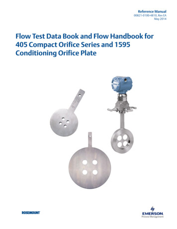
5. Click OK. If you receive a message that the name Chlorobenzene Modified is already being used,then do not create a new VOC. Instead, cancel and open the existing Chlorobenzene Modifiedto edit the input data.Change CHEMP.6 Data1.2.3.4.5.6.Click the CHEMP.6 tab near the top of the Edit VOC Data dialog.In the Reference Density for NAPL box, type 998.3.In the Reference Temperature for NAPL box, type 292.15.In the Reference Binary Diffusivity of VOC in Air box, type 8.0E-6.In the Reference Temperature for Gas Diffusivity box, type 273.15.In the Chemical Diffusivity Exponent box, type 1.0.Figure 1.2: Edit CHEMP.6 DataChange CHEMP.7 Data1.2.3.4.5.Click the CHEMP.7 tab.In the VLOA box, type 0.0.In the VLOB box, type 0.0.In the VLOC box, type 1.0.In the VLOD box, type 292.15.Change CHEMP.8 Data1. Click the CHEMP.8 tab.2. In the SOLA box, type 1.06E-7.3
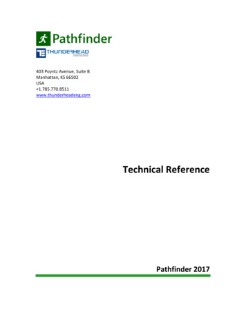
Change CHEMP.9 Data1.2.3.4.Click the CHEMP.9 tab.In the Chemical Organic Carbon Partition Coef. Box, type 0.0.In the Default Fraction of Organic Compound in Soil box, type 0.0.Click OK to close the Edit VOC Data dialog.Add to Active VOC List1. Select Chlorobenzene Modified in the VOC Library list.2. Click the right arrow (-- ) to move the selection to the Active Simulation VOCs list.3. Click OK to close the Global Properties dialog.Figure 1.3: Global PropertiesMaterial Properties1.2.3.4.5.On the Properties menu, click Edit Materials.In the Name box, type DIRT1.In the Porosity box, type 0.2.In the X, Y, Z Permeability boxes, type 2.96E-13.In the Wet Heat Conductivity box, type 3.1.4
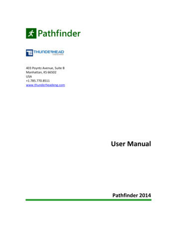
Define Additional Material Data1.2.3.4.5.6.Click the Additional Material Data button.In the Relative Permeability box, select Faust (1985). The default properties are correct.Click the Misc tab.In the Pore Compressibility box, type 1.0E-8.Click OK to close the Additional Material Data dialog.Click OK to close the Material Data dialog.Initial Conditions1.2.3.4.5.6.7.On the Properties menu, click Initial Conditions.In the Phase list, select 6 - Water and NAPL.In the Pressure box, type 6.895E5.In the Temperature box, type 19.0.In the Water Saturation box, type 0.159.In the Mole Fraction box for Chlorobenzene Modified, type 1.0.Click OK.Figure 1.4: Initial ConditionsEdit MeshTo make it easier to work with this 1D problem, you can scale the Y or Z axes. To scale the Y axis:1. On the View menu, click Scale Axes.2. In the Y Factor box, type 10.5
3. Click OK.At X 0, water is injected at a constant rate of 150.6E-6 kg/s. To name this cell, specify the waterinjection, and mark the cell for additional time history output:1.2.3.4.5.6.7.8.9.10.11.Click to select the left-most cell (or search for cell 1 in the Find box).On the Edit menu, click Properties.In the Cell Name box, type Injection.Click the Sources/Sinks tab.In the Available Components list, select Water/Steam.Select the Component is a Source check box.In the Rate box, type 1.506E-04.In the Enthalpy box, type 8.0E4.Click the Print Options tab.Select the Print Time Dependent Flow and Generation (BC) Data check box.Click OK to exit out of the Edit Cell Data dialog.Figure 1.5: Edit Cell Data dialogAt X 304.8, a fixed state is defined.1. Click to select the right-most cell (or search for cell 40 in the Find box).6
2.3.4.5.6.7.On the Edit menu, select Properties.In the Cell Name box, type Fixed.In the Type box, select Fixed State.Click the Print Options tab.Select the Print Time Dependent Flow and Generation (BC) Data check box.Click OK to exit out of the Edit Cell Data dialog.To generate additional time history output at the center cell:1.2.3.4.5.6.Click to select a cell near the center (or search for cell 19 in the Find box).On the Edit menu, click Properties.In the Cell Name box, type Center.Click the Print Options tab.Select the Print Time Dependent Flow and Generation (BC) Data check box.Click OK to exit out of the Edit Cell Data dialog.Solution Controls1.2.3.4.5.On the Analysis menu, click Solution Controls.In the End Time box, type 1500 days.In the Max Time Step dropbox, select User Defined.In the Max Time Step box, type 10 days.Click OK.7
Figure 1.6: Solution ControlsOutput Controls1.2.3.4.On the Analysis menu, click Output Controls.In the Print and Plot Every # Steps box, type 20.Click the Relative Permeability, Viscosity, and Enthalpies check box.Click OK.Save and Run1. On the File menu, click Save.2. On the Analysis menu, click Run TOUGH2.View ResultsYou can view 3D results using the 3D Results dialog. To view 3D results, on the Results menu, click 3DResults. To scale the Z-axis for better visualization:1.2.3.4.On the Results menu, click 3D Results.On the View menu, click Scale Axes.In the Y Factor box, type 50.0.Click OK.To show slice planes for oil saturation:8
1.2.3.4.5.6.In the left-hand navigation pane, click Slice Planes.In the Axis list, select Z.In the Coord box, type -0.5.Click Close.In the Time list, select the last entry (1.296E08).In the Scalar list, select SO.Figure 1.7: 3D ResultsWhen finished, you can close the 3D Results dialog.View Cell Time History PlotsTo view 2D time history plots for oil saturation:1. On the Results menu, select Cell History Plots.2. In the Variable list, select Soil.3. In the Cell Name list, select Center (19).9
Figure 1.8: Time history plot of oil saturation in center cellWhen finished, you can close the Cell Time History dialog.10
Print Time Dependent Flow and Generation (BC) Data. check box. 11. Click . OK. to exit out of the . Edit Cell Data. dialog. Figure 1.5: Edit Cell Data dialog . At X 304.8, a fixed state is defined. 1. Click to select the