Transcription
2
Donaldson Company, Inc.Process owners/operators have important responsibilities relating to combustible hazards.Process owners/operators must determine whether their process creates combustible dust,fume, or mist. If combustible dust, fume, or mist is generated, process owners/operators should at aminimum: Comply with all applicable codes and standards. Among other considerations, current NFPA standardsrequire owners/operators whose processes involve potentially combustible materials to have a currentHazard Analysis, which can serve as the foundation for their process hazard mitigation strategies. Prevent all ignition sources from entering any dust collection equipment. Design, select, and implement fire and explosion mitigation, suppression, and isolation strategies thatare appropriate for the risks associated with their application. Develop and implement maintenance work practices to maintain a safe operating environment, ensuringthat combustible dust, fume, or mist does not accumulate within the plant.Donaldson recommends process owners/operators consult with experts to insure each of theseresponsibilities are met.As a manufacturer and supplier of Industrial Filtration Products, Donaldson can assist process owners/operators in the selection of filtration technologies. However, process owners/operators retain allresponsibility for the suitability of fire and explosion hazard mitigation, suppression, and isolation strategies.Donaldson assumes no responsibility or liability for the suitability of any fire and/or explosion mitigationstrategy, or any items incorporated into a collector as part of an owner/operators hazard mitigation strategy.Improper operation of a dust control system may contribute to conditions in the work area or facility thatcould result in severe personal injury and product or property damage. Check that all collection equipment isproperly selected and sized for the intended use.DO NOT operate this equipment until you have read and understand the instruction warnings in theInstallation and Operations Manual. For a replacement manual, contact Donaldson Torit.This manual contains specific precautionary statements relative to worker safety. Read thoroughly and complyas directed. Discuss the use and application of this equipment with a Donaldson Torit representative. Instruct allpersonnel on safe use and maintenance procedures.Data SheetModel Number Serial NumberShip Date Installation DateCustomer NameAddressFilter TypeAccessoriesOther
Donaldson Company, Inc.DescriptionPurpose and Intended UseThe Downflo Oval dust collector is a continuousduty, modular collector with cartridge-style filters.The downward airflow design delivers high filtrationefficiency while using less energy. Continuous-dutymeans no downtime. The filters are pulse-cleaned insequence, one set at a time, without turning the unit off.The modular design allows flexibility in system designand adapts easily to limited space areas. Each standardmodule is two or three filter rows wide by two, three, orfour rows high by two filters deep.Downflo Oval collectors are widely used on nuisancedust where the load to the collector is less than fivegrains per cubic foot. Some typical applications includeabrasive blasting, grinding, pharmaceuticals, powderpaint applications, sand handling, and welding. Eachapplication is different and selecting the correct filtercartridge for the application and type of dust collected isimportant.Designed to increase the versatility of the unit, standardoptions include abrasion-resistant inlets, extended dirtyair plenums, and air management modules. For all ambient, extremely fine, and non-fibrous dust,use Ultra Web filter cartridges which offer highefficiency and performance on fine particulate. For fibrous dust, use a cartridge with an open-pleatdesign, such as Fibra-Web . Operations involving high temperature and highhumidity may require special attention. Temperature,moisture content, and chemistry issues may requirecustom collector design. Appropriate cartridgeoptions are available from Donaldson Torit. Hygroscopic dust such as fertilizer, salt, and sugarshould be handled under a controlled, low humidityenvironment. Contact Donaldson Torit for filtercartridge selection. Flammable or explosive dust may require customcollector design options and special cartridges.Contact Donaldson Torit for design assistance. Applications with high hydrocarbon or high oilcontent may require special treatment or filter media.Combustible materials such as buffing lint, paper, wood, metal dusts, weld fume, or flammablecoolants or solvents represent potential fire and/or explosion hazards. Use special care whenselecting, installing, and operating all dust, fume, or mist collection equipment when such combustiblematerials may be present in order to protect workers and property from serious injury or damage due to afire and/or explosion.Consult and comply with all National and Local Codes related to fire and/or explosion properties ofcombustible materials when determining the location and operation of all dust, fume, or mist collectionequipment.Standard Donaldson Torit equipment is not equipped with fire extinguishing or explosion protection systems.1
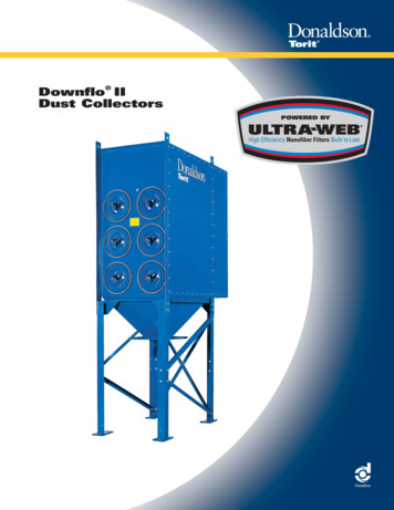
Donaldson Company, Inc.OperationDuring normal operation, dust-laden air enters the unitthrough the dirty-air inlet. Airflow is directed downwardthrough the collector and heavier particulate fallsdirectly into the hopper. The cartridges remove fineparticulate and clean, filtered air passes through thecartridge to the clean-air plenum and discharges throughthe clean-air outlet.Filter cleaning is completed using pulse-jet technology.A solenoid and diaphragm valve aligned to each rowof filters provides the pulse cleaning. The cleaningsequence starts at the top filter row and continues downthrough each module. Remove, inspect, or change thecartridges from outside the unit by removing the filteraccess cover and sliding the filters out.dirty-air routletcompressed-airsupplyExtraLife"filter cleaningsystemfilter cartridgeshopperNormal OperationFilter Cleaning OperationUnit Operation3
Downflo Oval, DFO 2-8 to 4-128Inspection on ArrivalInstallation1. Inspect unit on delivery.Site suitability must accountfor wind, seismic zone, andother live-load conditions when selecting thelocation for all units.2. Report any damage to the delivery carrier.3. Request a written inspection report from the ClaimsInspector to substantiate any damage claim.Codes may regulate acceptable locations forinstalling dust collectors. Consult with theappropriate authorities having jurisdiction toensure compliance with all national and localcodes regarding dust collector installation.4. File claims with the delivery carrier.5. Compare unit received with description of productordered.6. Report incomplete shipments to the delivery carrierand your Donaldson Torit representative.7. Remove crates and shipping straps. Remove loosecomponents and accessory packages before liftingunit from truck.8. Check for hardware that may have loosened duringshipping.9. Use caution removing temporary covers.Installation Codes and ProceduresCodes may regulate recirculatingfiltered air in your facility.Consult with the appropriate authoritieshaving jurisdiction to ensure compliancewith all national and local codes regardingrecirculating filtered air.Safe and efficient operation of the unit depends onproper installation.Authorities with jurisdiction should be consultedbefore installing to verify local codes and installationprocedures. In the absence of such codes, install unitaccording to the National Electric Code, NFPA No.70-latest edition and NFPA 91 (NFPA 654 if combustibledust is present).A qualified installation and service agent must completeinstallation and service of this equipment.All shipping materials, including shipping covers, must beremoved from the unit prior to, or during unit installation.Failure to remove shippingmaterials from the unit willcompromise unit performance.NOTICEInspect unit to ensure all hardware is properly installedand tight prior to operating collector.Site Selection, Grade-Mounted Units1. The unit can be located on a reinforced concretefoundation or rooftop.2. Provide clearance from heat sources andinterference with utilities when selecting the locationfor suspended units.3. Portable units require no special installationaccommodations.Note:Units with explosion vents are not availablein portable configurations.When outdoor locations are selected, always mountmotors with drain holes pointed down for properdrainage of moisture.Unit LocationDonaldson Torit equipment is notdesigned to support site-installedducts, interconnecting piping, or electricalservices. All ducts, piping, or electricalservices supplied by others must be adequatelysupported to prevent severe personal injuryand/or property damage.When hazardous conditions or materials arepresent, consult with local authorities for theproper location of the collectorFoundation must be capable of supporting the entireweight of the unit, plus the weight of the collectedmaterial, piping, and ductwork.Prepare the foundation in the selected location. Installanchor bolts to extend a minimum of 1 3/4-inches abovefoundation.Locate the collector to ensure easy access toelectrical and compressed-air connections and routinemaintenance.4
Donaldson Company, Inc.Electrical WiringIf explosion protection devices are part of the system,locate the collector in accordance with local coderequirements (Example: NFPA 654). These codes mayrequire units handling combustible dust be located eitheroutside or against an exterior wall.Rigging InstructionsSuggested Tools & EquipmentClevis Pins and ClampsLifting SlingsCrane or ForkliftPipe SealantDrift PinsPipe WrenchesDrill and Drill BitsScrewdriversEnd WrenchesSocket WrenchesAdjustable WrenchSpreader BarsTorque Wrench (inch/lbs, 9/16-in Socket)Hoisting InformationFailure to lift the collectorcorrectly can result in severepersonal injury or property damage.Use appropriate lifting equipment and adoptall safety precautions needed for moving andhandling the equipment.A crane or forklift is recommended forunloading, assembly, and installation of thecollector.Location must be clear of all obstructions, suchas utility lines or roof overhang.Use all lifting points provided.Use clevis connectors, not hooks, on lifting slings.Use spreader bars to prevent damage to unit’s casing.Check the Specification Control drawing for weightand dimensions of the unit and components to ensureadequate crane capacity.Allow only qualified crane operators to lift the equipment.Refer to applicable OSHA regulations and local codeswhen using cranes, forklifts, and other lifting equipment.Lift unit and accessories separately and assemble afterunit is in place.Use drift pins to align holes in section flanges duringassembly.5Electrical work must beperformed by a qualifiedelectrician and comply with all applicablenational and local codes.Turn power off and lock out electricalpower sources before performing service ormaintenance work.Do not install in classified hazardousatmospheres without an enclosure rated forthe application.All electrical wiring and connections, including electricalgrounding, should be made in accordance with theNational Electric Code (NFPA No. 70-latest edition).Check local ordinances for additional requirements thatapply.The appropriate wiring schematic and electrical ratingmust be used. See unit’s rating plate for required voltage.If the unit is not furnished with a factory-mounteddisconnect, an electric disconnect switch havingadequate amp capacity shall be installed in accordancewith Part IX, Article 430 of the National Electrical Code(NFPA No. 70-latest edition). Check unit’s rating plate forvoltage and amperage ratings.Refer to the wiring diagram for the number of wiresrequired for main power wiring and remote wiring.
Downflo Oval, DFO 2-8 to 4-128Typical Installation1. Place hopper discharge-side upon ground or other level surface andattach legs to hopper.2. Assemble leg cross braces.3. Turn hopper and leg assembly overand lift into position over anchor bolts.4. Level hopper.5. Tighten all fasteners securely.6. Apply rope sealant to hopper flange.7. Lift unit over leg and hopper assemblyand lower slowly.8. Secure with bolts, washers,and nuts supplied.9. Remove crane.10. Apply sealant to hopper/cabinet seam.angle not toexceed 30 from vertical(min 60 from horizontal)Do Not lift withthis orientationApply sealantafter marriageof hopperto cabinet3/8-16 x 1 1/4-in bolt3/8-in flat washersealantmodule flangemodule flange3/8-in flat washer3/8-in lock washer3/8-16 hex nutTypical Installation6
Donaldson Company, Inc.Standard EquipmentStandard equipment consists of modules, hoppers, andlegs. The legs and hopper are assembled first and theunit is placed using a crane. Collectors with up to sevenmodules require one crane for installation and unitscontaining eight or more modules require two cranes.Field AssemblyLeg sets are designed for standard height collectorsand are rated as shown in the Rating and SpecificationInformation. Reference the drawing shown below andthe leg assembly drawing shipped with the leg set forproper location and assembly.1. Stand the hopper on the discharge end.Field assembly of modules may be required due totruck capacity, crane capacity, or specific customerrequirements. A detailed instruction drawing, shippedwith each module, provides specific assembly and liftinginstructions.If unit has been shipped with fully-assembled modules,skip to Hopper Installation.Leg and Hopper Installation2. Use drift pins to align holes.3. Reference the Leg Positioning and Leg and CrossBrace Assembly drawings. Attach the legs to thehopper gussets using the hardware supplied.4. Join multiple hoppers together at hopper gussetsusing the hardware supplied. Do not tightenhardware at this time.There are five hopper styles offered for the DownfloOval. A single-module wide that spans two portholes, asingle-module wide that spans three portholes, a doublemodule wide spanning four portholes, a tall steeper,single-module wide module which spans two portholes,and a single-module screw conveyor spanning twoportholes. All styles except the screw conveyor transitionto a single 10-in square discharge. The screw conveyorhopper transitions to a single 18-in square discharge.flat washerhex bolthex boltflat washerlegflat washerlock washerhex nuthex nutflat washerlock washerlegcross braceLeg and Cross Brace Assembly7
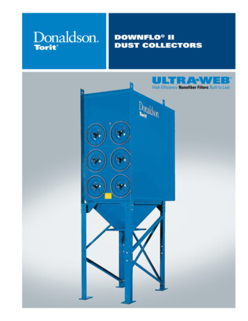
Downflo Oval, DFO 2-8 to 4-1285. Turn leg and hopper assembly over and position overanchor bolts. Secure each leg pad to the foundationanchor bolts with customer-supplied flat washers,lock washers, and nuts. Do not tighten hardware atthis time.single moduleDFO 2-8, 3-12and 4-16DFO 3-185-moduleDFO 3-60 and 4-808-moduleDFO 4-128dual moduleDFO 3-24DFO 2-16and 4-32and 2-246. Level hopper.7. Tighten all hardware securing legs, cross braces,hopper gussets, and foundation anchor bolts.Tighten all hardware beforeremoving crane.NOTICE3-moduleDFO 3-36and 4-486-moduleDFO 3-72 and 4-96DFO 2-364-moduleDFO 3-48 and 4-647-moduleDFO 4-1129-modulefor larger units supplied with extended dirty-airplenum and air management module10-modulefor larger units supplied with extendeddirty-air plenum and air management module11-modulefor larger units supplied with extendeddirty-air plenum and air management moduleLeg Positioning8
Donaldson Company, Inc.Module AssemblyNOTICETwo cranes are required to liftand assemble modules.1. Remove the protective cover from the end of eachmodule.2. Remove one column of access covers, filters,venturis, yokes, and deflector panels from the jointside of each module. See Detail A.4. Apply a generous amount of sealant to one module tocreate an airtight seal between the clean- and dirtyair plenums as shown in Detail B.5. Lift both modules into position using two cranes.6. Use drift pins to align the bolt holes in the matingflanges.3. Remove outlet cover from the bottom of the clean-airplenum and set aside.inlet deflector platesee Detail Eyoke, see Detail Fclean-airplenumfilter access coversee Detail Aoutlet coversee Detail Hdirty-airplenumModule Assembly9
Downflo Oval, DFO 2-8 to 4-1287. Bolt the modules together using 1/2-13 and 3/8-16 x 11/4-in bolts, washers, and nuts as shown Details B, C,and D. Do not tighten hardware at this time.8. Check that all joints and flanges are flush and tightenhardware starting with the joint between the cleanand dirty-air plenums. Remove excess sealant.1/2-13 x 1 1/4-in boltyoke, see Detail F1/2-in flat washersealantfiltercartridge1/2-in flat washer1/2-in lock washeraccesscovercoverhandle1/2-13 hex nutDetail CDetail A3/8-16 x 1 1/4-in boltclean-airplenumdirty-airplenumsealant3/8-in flat washersealantmodule flangemodule flangeDD CCCC3/8-in flat washer3/8-in lock washer3/8-16 hex nutDetail DDetail B10
Donaldson Company, Inc.Deflector Plate, Yoke, Venturi, and FilterInstallationNOTICEInstalling yokes requires twopeople.1. Attach deflector plates to the support angles using3/8-16 x 1 1/4-in bolts, washers, and nuts as shown inDetail E.2. From the clean air plenum (to access, remove theoutlet cover, see Detail H), thread a thin jam nut tothe shoulder of each of the two yoke rod ends. SeeDetail G and H.3. Start at the top access port and work downward.Position the yoke as shown in Detail F. From thefilter section, have one person hold the yoke inposition while another person installs the venturi andhardware from the clean-air plenum. See Detail H.Do not tighten hardware at this time.inlet deflector panel3/8 x 1 1/4-in bolt3/8 x 1 1/4-in bolt3/8-in flat washer3/8-in flat washer3/8-in flat washer3/8-in hex nutDetail E4. Adjust jam nut against the filter cartridge panel. Haveone person hold the yoke in position as shown inDetail F while another person tightens the three hexnuts from the clean-air plenum (see Detail H). Repeatto install all yokes.5. Slide the filter cartridge on the yoke gasket-end first.Replace access cover and tighten securely by hand.Repeat for all filter cartridges.yoke6. Replace the outlet cover on the bottom of the cleanair plenum. See Detail H.Detail F11
Downflo Oval, DFO 2-8 to 4-128venturi3/8-in hex nut3/8-in flat washer3/8-in lock washerfilter cartridge panel3/8-in hex jam nutyoke shoulderDetail G3/8-inflat washer3/8 x 1-inthread-formingscrewoutlet coverclean-air plenumDetail H12
Donaldson Company, Inc.Compressed Air InstallationTurn compressed-air supplyOFF and bleed lines beforeperforming service ormaintenance work.1. Remove the plastic pipe plug from the unit’s airmanifold and connect the compressed-air supplyline. Use thread-sealing tape or pipe sealant on allcompressed-air connections.A safety exhaust valve should be used toisolate the compressed air supply. The safetyexhaust valve should completely exhaustdownstream pressure when closed and includeprovisions to allow closed-position locking.2. Install a customer-supplied shut-off valve, bleedtype regulator with gauge, filter, and automaticcondensate valve in the compressed-air supply lineDo not set compressed-airpressure above 100-psig.Component damage can occur.NOTICEAll compressed air components must be sizedto meet the maximum system requirements of90-psig supply pressure.The compressed-air supply must be oiland moisture free. Contamination in thecompressed air used to clean filters will resultin poor cleaning, cleaning valve failure, or poorcollector performance.Purge compressed-air lines to remove debrisbefore connecting to the unit’s compressed-airmanifold.13
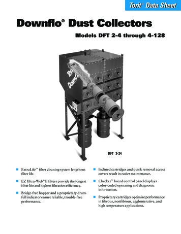
Downflo Oval, DFO 2-8 to 4-128dirty-air inlet duct*clean-air outletclean-air plenumdiaphragm valveair manifoldsolenoid enclosuresolenoid electricalconnection*air lineto manifolds*4air regulator*32bleed-type air filter*1
For a replacement manual, contact Donaldson Torit. This manual contains speci c precautionary statements relative to worker safety. Read thoroughly and comply as directed. Discuss the use and application of this equipment with a Donaldson Torit representative. Instruct all personnel on safe use and mainten