Transcription
LISA-U200 series3.75G UMTS/HSPA Wireless ModuleData SheetVersion : 2.12012.09.25Page 1 of 53
Revision HistoryRevisionDateDescriptionV1.02012.06.20First releasedV1.12012.07.10Modify some dataV2.02012.09.10Modify some dataV2.12012.09.25Modify pin definePage 2 of 53
ContentsContents 31 Functional description . 41.11.2Overview 4Product features . 41.31.41.51.6Block diagram . 5Product description . 6AT Command support . 7AssustNow clients and GPS integration (LISA-U200 only) .1.71.81.97In-Band modem . . 7Smart temperature supervision . 8TCP/IP and UDP/IP . 81.101.111.12FTP and FTPS . 9HTTP and HTTPS 9Jamming Detection . 91.13Hybrid positioning and CellLocate . 92 Mechanical Specifications . 112.12.22.3Dimensions and interfaces . 11Antenna connector . 14Dimensions of the Mini PCI Express Connector . 153 System description . 163.13.23.3Pin assignment . 16Operating modes . 17Module supply (VCC) 183.43.53.6Real Time Clock supply input/output (V BCKP) . 20System functions 22USB interface . 263.73.83.94.0Serial communication 27(U)SIM interface . 33Audio Interface . 35Network status indication . 384 Electrical specifications . 394.1 Maximum ESD 394.2 Operating conditions . 39Page 3 of 53
1 Functional description1.1 OverviewThe LISA-U200 HSPA series product is a combination of U-blox LISA-U200 and GPS MAX-6module. The LISA-U200 HSPA series mini PCIE module with an integrated SIM holder is idealfor consumer and industrial applications requiring high-speed data transmission rates, andmachine-to-machine applications. They are the perfect choice for mobile Internet terminals,tablets, in-car infotainment, connected navigation systems, security and surveillance system,eCall, fleet management, metering, anti-theft systems, and other automotive applications.The LISA-U200 HSPA series modules with 6-band WCDMA(UMTS) and quad-bandGSM/GPRS/EDGE are suited for networks worldwide. Featuring 7.2 Mb/s HSDPA downlink and5.76 Mb/s HSUPA uplink speeds, a rich set of Internet protocols, and very low powerconsumption and extended operating temperature range. LISA-U200 module provide fullyintegrated access to u-blox GPS receivers. Wire-less and GPS are controlled through a singleserial port from any host processor.1.2 Product features1Page 4 of 53FW update via serial1AssistNow software1SSL1FTP , HTTP800/850/900/1700/1900/2100Embedded TCP/UDP7.2Network indicationLISA-U202 5.76Integrated SIM holder1FunctionGPS / A-GPS2Digital Audio (4-wire I2C)1GPRS/EDGE quad-band1UMTS/HSPA [MHz]800/850/900/1700/1900/2100HSDPA [Mb/s]7.2HSUPA [Mb/s]LISA-U200 5.76Analog AudioAudioUICC/SIM card interfaceInterfaceU.FL-R-SMT 50Ω antenna connectorBandsUSBTechnologyUARTModule
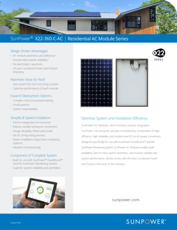
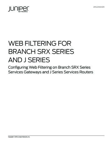
1.3 Block diagramSIM slotUSIMUARTV BCKP(RTC)ExternalResetUSBPCI express mini cardDigitalAudio2(I S)USB DET 5.0VVCC 4.2VGPIOVCC3.8VLISA-U200I2C(DCC)GPIOVCC 5VFor VUSB-DETDC/DC converterVCC 3.3VVCC 1.8VVCC 1.8VMAX-6GMAX-6GNote: LISA-U202 model does not include MAX-6G GPS block.Page 5 of 53
1.4 Product descriptionLISA-U200 series wireless modules integrate full-feature 3G UMTS/HSxPA and 2GGSM/GPRS/EDGE protocol stack with Assisted GPS support. These modules withintegrated SIM holder and compatible Mini PCIE spec. standard interface revision 1.0 & 1.2 .3G UMTS/HSDPA/HSUPA Characteristics12G GSM/GPRS/EDGE Characteristics2Class A User EquipmentUMTS Terrestrial Radio Access (UTRA) Frequency DivisionDuplex (FDD) operating modeClass B Mobile StationSix-band support: Band I (2100 MHz), Band II (1900 MHz),Band IV (1700 MHz), Band V (850 MHz),Band VI (800 MHz), Band VIII (900 MHz)Quad-band supportGSM 850 MHz, E-GSM 900 MHz,DCS 1800 MHz, PCS 1900 MHzWCDMA/HSDPA/HSUPA Power Class Power Class 3 (24 dBm) for WCDMA/HSDPA/HSUPA modeGSM/GPRS Power Class 4 (33 dBm) for GSM/E-GSM bands Power Class 1 (30 dBm) for DCS/PCS bandsEDGE Power Class Power Class E2 (27 dBm) for GSM/E-GSM bands Power Class E2 (26 dBm) for DCS/PCS bandsPS (Packet Switched) Data Rate HSUPA category 6, up to 7.2 Mb/s DL, 5.76 Mb/s UL HSDPA category 8, up to 7.2 Mb/s DL, 384 kb/s UL WCDMA PS data up to 384 kb/s DL/ULPS (Packet Switched) Data Rate3 GPRS multislot class 33 , coding scheme CS1-CS4,up to 107kb/s DL, 85.6kb/s UL3 EDGE multislot class 33 , coding scheme MCS1MCS9, up to 296kb/s DL, 236.8 kb/s ULCS (Circuit Switched) Data Rate WCDMA CS data up to 64 kb/s DL/ULCS (Circuit Switched) Data Rate GSM CS data up to 9.6kb/s DL/UL supported intransparent/non transparent modeTable 1: LISA-U200 series module UMTS/HSDPA/HSUPA and GSM/GPRS/EDGE characteristicsOperation modes I to III are supported on GSM/GPRS network, with user-defined preferredservice selectable from GSM to GPRS. Paging messages for GSM calls can be optionallymonitored during GPRS data transfer in not-coordinating NOM II-III.The network automatically configures the number of timeslots used for reception ortransmission (voice calls take precedence over GPRS traffic) and channel encoding (CS1 toMCS9). The maximum (E)GPRS bit rate of the mobile station depends on the coding schemeand number of time slots. Direct Link mode is supported for TCP and UDP sockets.1 Device can work simultaneously in Packet Switch and Circuit Switch mode: voice calls are possible while the dataconnection is active without any interruption in service.2 Device can be attached to both GPRS and GSM services (i.e. Packet Switch and Circuit Switch mode) using one service ata time. If for example during data transmission an incoming call occurs, the data connection is suspended to allow the voicecommunication. Once the voice call has terminated, the data service is resumed.3 GPRS/EDGE multislot class 12 implies a maximum of 5 slots in DL (reception) and 4 slots in UL (transmission) with 6 slots intotal. GPRS class determines the number of timeslots available for upload and download and thus the speed at which data canbe transmitted and received, with higher classes typically allowing faster data transfer rates.Page 6 of 53
4Basic featuresDisplay of Called NumberIndication of Call Progress SignalsCountry/PLMN IndicationInternational Access FunctionService IndicatorDual Tone Multi Frequency (DTMF)Subscription Identity ManagementService Provider IndicationAbbreviated DialingSIM ToolkitSupplementary servicesCall Hold/Resume (CH)Call Waiting (CW)Short Message Service (SMS)SMS Classes 1, 2, 3Mobile-Originating SMS (MO SMS)Multi-Party (MTPY)Call Forwarding (CF)Call DivertExplicit Call Transfer (ECT)Call Barring (CB)Call Completion to Busy Subscriber(CCBS)Advice of Charge Charging (AOCC)Calling Line Identification Presentation(CLIP)Calling Line Identification Restriction(CLIR)Connected Line IdentificationPresentation (COLP)Connected Line Identification Restriction(COLR)Unstructured Supplementary ServicesData (USSD)Network Identify and Time Zone (NITZ)Mobile-Terminating SMS (MT SMS)SMS Cell Broadcast (SMS CB)Text and PDU mode supportedSMS during circuit-switched callsSMS over PSD or CSDSMS storage on SIM and memorymodule4Table 2: Basic Features , Supplementary Services, and Short Message Service (SMS)1.5 AT Command supportThe module supports AT commands according to 3GPP standards: TS 27.007 [1], 27.005 [2],27.010 [3], and the u-blox AT command extension.For the complete list of the supported AT commands and their syntax see the u-bloxAT Commands Manual [5].4These functionalities are supported via AT commands (for more details see the u-blox AT Commands Manual [5]).1.6 AssustNow clients and GPS integration (LISA-U200 only)LISA-U200 module feature embedded AssistNow Online and AssistNow Offline clients.AssistNow A-GPS provides better GPS performance and faster Time-To-First-Fix. The clientscan be enabled / disabled with an AT command.The wireless modules act as a stand-alone AssistNow client, making AssistNow available withno additional requirements for resources or software integration on an external host microcontroller.This means that GSM/WCDMA and GPS can be controlled through a single serial port from anyhost processor.Page 7 of 53
1.7 In-Band modemLISA-U200 supports In-Band modem for eCall, according to the 3GPP TS 26.267 specification[8]. According to the eCall (Pan-European automatic in-vehicle emergency call system)specification, an eCall must be generated automatically or manually following a car accident,using GSM cellular service “112”. When activated, the in-vehicle eCall system (IVS) creates anemergency call carrying both voice and data (e.g. vehicle GPS position) directly to the nearest112 Public Safety Answering Point (PSAP) to quickly decide upon detaching rescue services tothe known position.In-Band modem diagram flowIn-band modem allows the fast and reliable transmission of vehicle Minimum Set of Data (MSD 140 bytes) and the establishment of a voice emergency call using the same physical channel(voice channel) without any modifications of the existing cellular network architecture.In-Band modem is a mandatory feature to meet the eCall requirements and to develop invehicle devices fully supporting eCall.1.8 Smart temperature supervisionAn internal sensor is used to constantly monitor the board temperature of LISA-U200 seriesmodules. The measured value is compared with the internally predefined thresholds and itaccordingly proceeds.A shutdown is notified and automatically forced by the module when the temperature value isoutside the specified range (i.e. the module is in a dangerous working condition). For securityreasons the shutdown is suspended in case of emergency call in progress: in this case thedevice will switch off at call termination.The Smart Temperature Supervisor feature can be enabled or disabled via an AT command (formore details please to u-blox AT commands manual [5], USTS AT command). If the feature isdisabled there is no embedded protection against not allowed temperature working conditions.The sensor measures the board temperature inside the shields, which can differ fromambient temperature.Page 8 of 53
1.9 TCP/IP and UDP/IPVia AT commands it is possible to access the TCP/IP and UDP/IP functionalities over thePacket Switched Data (PSD) connection. For more details about AT commands see the u-bloxAT Commands Manual [5].Direct Link mode for TCP and UDP sockets is supported. Sockets can be set in Direct Linkmode to establish a transparent end to end communication with an already connected TCP orUDP socket via serial interface.1.10 FTP and FTPSLISA-U200 series modules support the File Transfer Protocol as well as Secure File TransferProtocol functionalities via AT commands. Files are read and stored in the local file system ofthe module. For more details about AT commands see u-blox AT Commands Manual [5].1.11 HTTP and HTTPSHTTP and HTTPS client are implemented in LISA-U200 series modules. HEAD, GET, POST,DELETE and PUT operations are available. The file size to be uploaded or downloadeddepends on the free space available in the local file system (FFS) at the moment of theoperation. Up to 4 client contexts can be simultaneously used.For more details about AT commands see the u-blox AT Commands Manual [5].1.12 Jamming DetectionIn real network situations, modules can experience various out-of-coverage conditions: limitedservice conditions when roaming to networks not supporting the specific SIM, limited service incells which are not suitable or barred due to operators’ choices, no cell conditions when movingto poorly served or highly interfered areas. In the latter case, interference can be artificiallyinjected in the environment by a noise generator covering a given spectrum, thus obscuring theoperator’s carriers entitled to give access to the GSM/UMTS service.The Jamming Detection Feature detects such “artificial” interference and reports the start andstop of such conditions to the client, which can react appropriately by e.g. switching off the radiotransceiver in order to reduce power consumption and monitoring the environment at constantperiods.The jamming detection feature can be enabled and configured by the UCD AT command (formore details refer to the u-blox AT Commands Manual [5]).1.13 Hybrid positioning and CellLocateAlthough GPS is a widespread technology, its reliance on the visibility of extremely weak GPSsatellite signals means that positioning is not always possible. Especially difficult environmentsfor GPS are indoors, in enclosed or underground parking garages, as well as in urban canyonsPage 9 of 53
where GPS signals are blocked or jammed by multipath interference. The situation can beimproved by augmenting GPS receiver data with cellular network information to providepositioning information even when GPS reception is degraded or absent. This additionalinformation can benefit numerous applications.1.13.1 Positioning through cellular information: CellLocateu-blox CellLocate enables the estimation of device position based on the parameters of themobile network cells visible to the specific device. To estimate its position the u-blox wirelessmodule sends the CellLocate server the parameters of network cells visible to it using a UDPconnection. In return the server provides the estimated position based on the CellLocatedatabase. The u-blox wireless module can either send the parameters of the visible homenetwork cells only (normal scan) or the parameters of all surrounding cells of all mobileoperators (deep scan).CellLocate is implemented using a set of two AT commands that allow configuration of theCellLocate service (AT ULOCCELL) and requesting position according to the userconfiguration (AT ULOC). The answer is provided in the form of an unsolicited AT commandincluding latitude, longitude and estimated accuracy.Normal scan is only possible in 2G mode.1.13.2 Hybrid positioningWith u-blox Hybrid positioning technology, u-blox wireless devices can be triggered to providetheir current position using either a u-blox GPS receiver or the estimated position fromCellLocate. The choice depends on which positioning method provides the best and fastestsolution according to the user configuration, exploiting the benefit of having multiple andcomplementary positioning methods.Hybrid positioning is implemented through a set of three AT commands that allow configurationof the GPS receiver (AT ULOCGNSS), configuration of the CellLocate service(AT ULOCCELL), and requesting the position according to the user configuration (AT ULOC).The answer is provided in the form of an unsolicited AT command including latitude, longitudeand estimated accuracy (if the position has been estimated by CellLocate), and additionalparameters if the position has been computed by the GPS receiver.u-blox is extremely mindful of user privacy. When a position is sent to the CellLocateserver u-blox is unable to track the SIM used or the specific device.Page 10 of 53
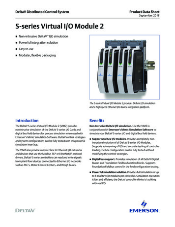
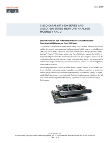
2 Mechanical Specifications2.1 Dimensions and interfacesThe dimension of LISA-U200 module is 50.85mm(length) x 29.9mm(width) x 6.7mm(height),Figure 2-1-1 shows the dimensions of LISA-U200 module in details.Figure 2-1-1 Dimensions of LISA-U200 modulePage 11 of 53
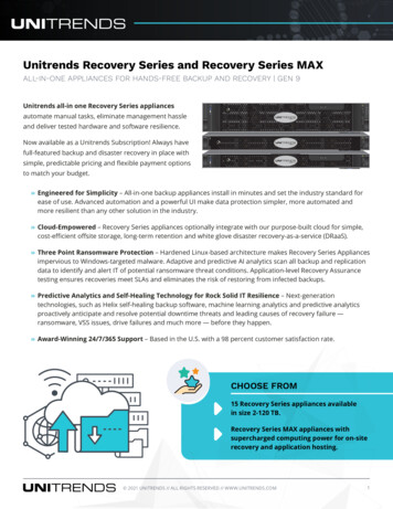
The dimension of LISA-U202 module is 50.85mm(length) x 29.9mm(width) x 6.2mm(height),Figure 2-1-2 shows the dimensions of LISA-U202 module in details.Figure 2-1-2 Dimensions of LISA-U202 modulePage 12 of 53
Figure 2-1-3 Appearance of the interfaces on LISA-U200 series module2PIN 511Top SizePIN 1PIN 234PIN 52Bottom Size1.2.3.4.Mini PCI Express connector – It’s used to connect LISA-U200 series module to theWWAN Mini PCI Express interface of the PC.RF main antenna connector.GPS antenna connector.SIM holder.2.1.1 RF Antenna guidelinesAntenna characteristics are essential for good functionality of the module. Antenna radiatingperformance has direct impact on the reliability of connections over the Air Interface. A badtermination of the ANT pin (main RF input/output) can result in poor performance of themodule.The following parameters should be checked:ItemRecommendationsImpedance50 Ω nominal characteristic impedancePage 13 of 53
Frequency Range 824.960 MHz (GSM 850, GSM 900, UMTS B5, UMTS B6, UMTS B8) 1710.2170 MHz (GSM 1800, GSM 1900, UMTS B1, UMTS B2, UMTS B4)Input Power 2 W peakV.S.W.R 2:1 recommended, 3:1 acceptableReturn LossS11 -10 dB recommended, S11 -6 dB acceptableGain 3 dBiTable 2-1-1 : General recommendation for GSM/UMTS antenna2.1.2 GPS Antenna guidelinesThe modules are designed for use with Active antennas.ParameterSpecificationAntenna TypeActive antennaActive AntennaRecommendationsMinimum gainMaximum gainMaximum noise figure15 dB (to compensate signal loss in RF cable)50 dB1.5 dBTable 2-1-2 : Antenna Specifications for GPS antennaWe recommend to use the online GA002-03 GPS active antenna, For more information youcan refer to the Company web: http://ontech-corp.com/2.2 Antenna connectorThe antenna connector type used is a U.FL microwave coaxial connector. It is also can be usedfor testing purpose.Page 14 of 53
2.3 Dimensions of the Mini PCI Express ConnectorLISA-U200 series modules adopts a standard mini PCIE connector that has 52 pins andcomplies with the PCIE mini card electromechanical specification revision 1.2.Figure 2-3-1 show a 52-pin Mini PCI Express connector for LISA-U200 series module use.(take the ChiTek AKP-3B0A-052-3 as an example).Figure 2-3-1 Dimensions of the Mini PCI Express connectorPage 15 of 53
Page 16 of 53
3 System description3.1 Pin assignmentPIN No.NameDescribePIN No.NameDescribe1NC2VCC3RI4GND5NC6NC7NC8UIM PWRO , SIM supply output 1.8/3.0V9GND10UIM DATAI/O ,SIM data11NC12UIM CLKO , SIM clock13NC14UIM RESETO , SIM reset15GND16NC17V BCKPI/O , Real time clock supplyinpot/output18GND19UART CTSO , UART clear to send20NC21GND22RESET NI , External reset input23UART RXDO , UART received data24VCCI , Module supply input25UART RTSI , UART ready to send26GND27GND28NC29GND30NC31UART TXDI , UART transmitted data32NC33UARD DCDO , UART data carrier detect34GND35GND36USB D-I/O , USB data line D-37GND38USB D USB , USB data line D 39VCCI , Module supply input40GND41VCCI , Module supply input42LED WAN#O , Network status indication43GND44UART DTRI , UART data terminal ready45I2S CLKO , I2S clock46UART DSRO , UART data set ready47I2S TXDO , I2S transmit data48NC49I2S RXDI , I2S receive data50GND51I2S WAO , I2S word alignment52VCCI , Module supply inputI , Module supply inputPage 17 of 53
3.2 Operating modesLISA-U200 series modules have several operating modes. Table 3-2-1 summarizes the variousoperating modes and provides general guidelines for operation.Table 3-2-1 : Module operating modes summaryPage 18 of 53
Transition between the different modes is described in Figure 3-2-2.Figure 3-2-2 : Operating modes transition3.3 Module supply (VCC)The LISA-U200 series modules must be supplied through the VCC pins by a DC power supply.Voltages must be stable: during operation, the current drawn from VCC can vary by someorders of magnitude, especially due to surging consumption profile of the GSM system It isimportant that the system.NameVCCDescriptionModule power supply inputRemarksVCC pins are internally connected, but all theavailable pads must be connected to the externalsupply in order to
The LISA-U200 HSPA series product is a combination of U-blox LISA-U200 and GPS MAX-6 module. The LISA-U200 HSPA series mini PCIE module with an integrated SIM holder is ideal for consumer and industrial app