Transcription
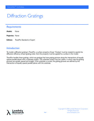
TRACEPROTUTORIALDiffraction GratingsRequirementsModels:NoneProperties: NoneEditions:TracePro Standard or ExpertIntroductionTo model a diffraction grating in TracePro, a surface property of type “Grating” must be created to specify thediffraction efficiency of each grating order, then the property must be applied to a surface in the model.TracePro handles linear gratings, which are gratings that have grating grooves along the intersections of equallyspaced parallel planes with a substrate surface. The substrate surface may be a plane, in which case the gratinggrooves are equally spaced and straight. If the substrate is curved, the grating grooves are defined by theintersection of equally spaced parallel planes with the substrate.Page 1Copyright 2008 Lambda Research Corporation.All Rights Reserved.www.lambdares.com
TRACEPROTUTORIALDiffraction GratingsCreating a Grating-Type Surface Property1. Select Define/Edit Property Data/Surface Properties to open the Surface Property Editor.2. Select an existing catalog or create a new catalog (Add Catalog) for this new property3. Select “Add Property”, give the property a name, and select the Scatter Model as ABg4. In the Surface Property Ediitor, select the property type to be “Grating”Page 2www.lambdares.com
TRACEPROTUTORIALDiffraction GratingsAdd Grating Orders to the PropertyAdd Grating Orders to the Surface Property by clicking Add in the Data Points section. Add the orders -1, 0, 1, 2 by typing eachnew order in the Add dialog box and clicking Apply after each one as shown below.Page 3www.lambdares.com
TRACEPROTUTORIALDiffraction GratingsEntering Data in the Grating Surface PropertyThe efficiency is the fraction of the incident flux that is diffracted into that order. TracePro computes the sum of all the reflectionefficiencies and puts that value in the Total row on the on the bottom of the input for the current data subset, and likewise for thetransmission efficiencies. For a Grating surface property, then, the specular reflectance and transmittance cannot be entered directlyas in other Surface Properties. However, the absorptance, BRDF, and BTDF are entered in the usual way, and you may solve forthe absorptance, BRDF, or BTDF. You may also enter as many angles of incidence as you wish, the same as for a Table type surfaceproperty. Finally, a value must be entered for the grating spacing. This is the distance between the parallel planes used to form thegrating.For this example grating surface property, with just one angle of incidence, enter the Grating Apacing as 1, the efficiency for each ofthe 4 grating orders as .1, .4, .2, .1, define the BRDF with A 0.002, B 0.001, and g 2, then solve for Absorptance.This surface property is a reflection grating, and we have added a BRDF as well. When you specify a BRDF, the Integrated BRDF orTotal Scatter (TS) will be split up between the diffracted orders, in proportion to the efficiency.Page 4www.lambdares.com
TRACEPROTUTORIALDiffraction GratingsApplying the Grating Surface Property1.2.3.4.Select File/New to open a new TracePro Model,and select Insert/Primitive Solids/Block to createan object for the Grating Surface Property to beapplied to.Select Surface 4 in the System Tree and selectDefine Apply Properties Surfaceto to open theApply Properties dialog. When you select thegrating property from the Surface Property dropdown list, a field appears for an Up Direction to beentered.The Up Direction is a unit vector that isperpendicular to the grating planes, and points inthe direction of positive diffracted orders. Thediagram to the right shows a Rectangular substratewith grating formation planes. In this example, thegrating Up Direction could be along the x or -xaxis.For our model, enter (1,0,0) for the Up Vector,and click Apply.Page 5www.lambdares.com
TRACEPROTUTORIALDiffraction GratingsRaytracing a Grating Surface PropertyWhen a ray intersects a surface with a Grating Surface Property applied, TracePro will interpolate the efficiency data for the givenangle of incidence. If the direction of incidence is such that one or more orders cannot exist, the flux from those orders will be givento the remaining orders, in proportion to their efficiencies.To trace rays in our model, select Define/Grid Source, enter the values shown below, then click “Trace This”In our grating property, the grating has reflected orders only, and a BRDF is defined. The scattered rays have flux below the defaultflux threshold of 0.05, so they are not traced.Page 6www.lambdares.com
TRACEPROTUTORIALDiffraction Gratings2nd Raytrace with lower Flux ThresholdSelect Analysis/raytrace options/Thresholds and decrease the flux threshold to 0.001, then repeat the raytrace. Now the lower-fluxscattered rays are traced, and there is one scattered ray for each diffracted order.Page 7www.lambdares.com
grating. For this example grating surface property, with just one angle of incidence, enter the Grating Apacing as 1, the efficiency for each of the 4 grating orders as .1, .4, .2, .1, define the BRDF with A 0.002, B 0.001, and g 2, then solve for Absorptance. This surface property is a reflection grating, and we have added a BRDF as well.