Transcription
Open Journal of Fluid Dynamics, 2018, 8, 286-307http://www.scirp.org/journal/ojfdISSN Online: 2165-3860ISSN Print: 2165-3852Comparison of RANS and LES in the Predictionof Airflow Field over Steep Complex TerrainTakanori Uchida1*, Graham Li2Research Institute for Applied Mechanics (RIAM), Kyushu University, Fukuoka, JapanTsubasa Windfarm Design, Tokyo, Japan12How to cite this paper: Uchida, T. and Li,G. (2018) Comparison of RANS and LES inthe Prediction of Airflow Field over SteepComplex Terrain. Open Journal of FluidDynamics, 8, eived: November 13, 2017Accepted: August 31, 2018Published: September 3, 2018Copyright 2018 by authors andScientific Research Publishing Inc.This work is licensed under the CreativeCommons Attribution InternationalLicense (CC BY en AccessAbstractThe present study compared the prediction accuracy of the three CFD software packages for simulating airflow around a three-dimensional, isolated hillwith a steep slope: 1) WindSim (turbulence model: RNG k-ε RANS), 2) Meteodyn WT (turbulence model: k-L RANS), which are the leading commercially available CFD software packages in the wind power industry and 3)RIAM-COMPACT (turbulence model: standard Smagorinsky LES), whichhas been developed by the lead author of the present paper. Distinct differences in the airflow patterns were identified in the vicinity of the isolated hill(especially downstream of the hill) between the RANS results and the LESresults. No reverse flow region (vortex region) characterized by negative windvelocities was identified downstream of the isolated hill in the result from thesimulation with WindSim (RNG k-ε RANS) and Meteodyn WT (k-L RANS).In the case of the simulation with RIAM-COMPACT natural terrain version(standard Smagorinsky LES), a reverse flow region (vortex region) characterized by negative wind velocities clearly forms. Next, an example of wind risk(terrain-induced turbulence) diagnostics was presented for a large-scale windfarm in China. The vertical profiles of the streamwise (x) wind velocity do notfollow the so-called power law wind profile; a large velocity deficit can beseen between the hub center and the lower end of the swept area in the case ofthe LES calculation (RIAM-COMPACT).KeywordsRANS, LES, Isolated Hill, Large-Scale Wind Farm1. IntroductionWe have developed an unsteady and non-linear wind synopsis simulator calledRIAM-COMPACT (Research Institute for Applied Mechanics, Kyushu UniverDOI: 10.4236/ojfd.2018.83018 Sep. 3, 2018286Open Journal of Fluid Dynamics
T. Uchida, G. Lisity, Computational Prediction of Airflow over Complex Terrain) in order tosimulate the airflow on a microscale, i.e., a few tens of km or less [1]-[13]. InRIAM-COMPACT, a large-eddy simulation (LES) has been adopted for turbulence modeling. LES is a technique in which the structures of relatively large eddies are directly simulated and smaller eddies are modeled using a sub-grid scalemodel. Efforts have been made to promote RIAM-COMPACT, mainly in thewind power industry (e.g., private wind power providers, local governments, andwind turbine manufacturers) in Japan. Computation time had been an issue ofconcern for the RIAM-COMPACT software, which focuses on unsteady turbulence simulations (LES). The present fluid simulation solver is compatible withmulti-core CPUs such as the Intel Core i9 and also with GPGPU, which hasdrastically reduced the computation time, leaving no appreciable problems interms of the practical use of the RIAM-COMPACT software.On another front, commercially available CFD software such as STAR-CCM [14] and ANSYS (CFD, Fluent, CFX) [15] has developed mainly as an engineering tool primarily in the automobile and aviation industries until the presenttime. Recently, some of the above-mentioned general purpose thermal fluidanalysis software has started being adopted in the wind power industry. In theprevious study [16] [17] [18], the simulation results obtained from theRIAM-COMPACT software were compared to those from STAR-CCM , one ofthe leading commercially available CFD software packages. The results of thecomparison are discussed. In addition, open-source CFD software packages aremore widely used than in the past. One of the most widely used software packages is OpenFOAM (OpenField Operation And Manipulation) [19]. OpenFOAM is an open-source CFD toolbox which has been released and distributedunder the GNU GPL (General Public License) [20] by the OpenFOAM Foundation, a non-profit organization. In the previous study [21], the simulation resultsobtained from the RIAM-COMPACT software were also compared to thosefrom OpenFOAM, and the results of the comparison are discussed.The wind power industry has on its own developed and distributed CFDsoftware designed for selecting sites appropriate for the installation of wind turbine generators. One such leading software package is Meteodyn WT [22],which has been developed by Meteodyn in France. Meteodyn WT is a CFDsoftware package which incorporates a RANS turbulence equation with aone-equation closure scheme (k-L turbulence model; here, k and L refer to turbulence energy and the turbulence length scale, respectively). On October 12,2017, “WT6.0”, the latest version of the software, was released. Another one ofthe most widely used software packages is WindSim [23] by Norway-basedWindSim AS. WindSim is a CFD software package which uses a RANS turbulence model and has been designed specifically for wind resource assessment. InDecember 2016, the latest version of the company’s software package, WindSim8.0, was released. These two CFD software packages are specialized for windpower resource assessment as well as the RIAM-COMPACT CFD software package.DOI: 10.4236/ojfd.2018.83018287Open Journal of Fluid Dynamics
T. Uchida, G. LiIn the present study, numerical simulations are performed for airflow overand around a three-dimensional, isolated hill with a steep slope angle using thethree CFD software packages (WindSim, Meteodyn WT and RIAM-COMPACT).The results of the comparison are discussed. Next, the numerical simulations forairflow over a large-scale wind farm in China [21] are performed withRIAM-COMPACT, which is based on an LES turbulence model, and MeteodynWT, which is based on a RANS turbulence model.2. Overview of the Software Packages (RIAM-COMPACT andWindSim) and Numerical Simulation Set-Up in the Case ofa Three-Dimensional, Isolated Hill with a Steep SlopeAngleThe numerical wind simulations in the present study are conducted for highReynolds number airflow over and around a three-dimensional, isolated hillwith a steep slope angle and a large-scale wind farm in China. Table 1 shows thesimulation set-ups adopted in the two software packages which are used inTable 1. Comparison of numerical simulation methods, parameters, and settings betweenthe two software packages.CFD modelRIAM-COMPACTWindSimTurbulence modelStandard Smagorinsky LESRNG k-ε RANSAtmospheric stratification(Atmospheric stability)Neutral atmosphereCoriolis forceNot consideredSurface roughnessNot considered(Smooth surface)Roughness length: 0.001Ground surfaceboundary conditionNon-slip condition(Three wind velocity componentsat the ground surface are zero.)Wall functionShape function ofthe isolated hill z (r)0.5h {1 cos(πr/a)}, r (x2 y2)1/2, a 2hHeight of the isolated hill hReynolds number Re ( Uinh/ν)Time step ΔtComputational domain sizeNumber ofcomputational grid pointsStreamwise (x) grid spacing (Δx)Spanwise (y) grid spacing (Δy)Vertical (z) grid spacing (Δz)DOI: 10.4236/ojfd.2018.83018288100 (m)5 10 and 1 1045 104 and 1 107710 3 h/Uin (s) for Re 5 10410 7 h/Uin (s) for Re 1 10713h (i) 9h (j) 8h (k)for Re 5 10419h (i) 18h (j) 8h (k)for Re 1 107325 (i) 226 (j) 37 (k)(Approx. 2.7 million points)for Re 5 104436 (i) 325 (j) 101 (k)(Approx. 14.3 million points)for Re 1 107-13h (i) 9h (j) 8h (k)325 (i) 226 (j) 37 (k)(Approx. 2.7 million points)0.04 h for Re 5 104(0.035 - 0.5) h for Re 1 1070.04 h(0.05 - 0.40) h for Re 5 104(0.000004 - 0.6) h for Re 1 107(0.05 - 0.40) hOpen Journal of Fluid Dynamics
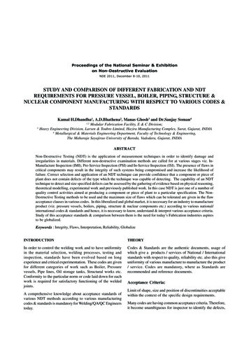
T. Uchida, G. Lithe present study: RIAM-COMPACT natural terrain version (turbulence model:LES) and WindSim (turbulence model: RANS). Figure 1 and Figure 2 illustratethe full computational grid used for WindSim and an enlarged view of the gridin the vicinity of the isolated hill, respectively. Figure 3 shows the inflow profileused for all of the simulations in the present study. Figure 4 shows the characteristic wind velocity and length scales which are employed for the simulationswith RIAM-COMPACT.In RIAM-COMPACT, a collocated grid in a general curvilinear coordinatesystem is used in order to numerically predict local wind flow over complex terrain with high accuracy while avoiding numerical instability. For the numericalsimulation method, a FDM is adopted, and an LES model is used for the turbulence model. For the computational algorithm, a method similar to a FS method[24] is used, and a time marching method based on the Euler explicit method isadopted. The Poisson’s equation for pressure is solved by the SOR method.Figure 1. Computational grid used in the simulations with WindSim, Re 5 104 and 5 107.Figure 2. Enlarged view of the computational grid used in the simulations with WindSim,Re 5 104 and 5 107.DOI: 10.4236/ojfd.2018.83018289Open Journal of Fluid Dynamics
T. Uchida, G. LiFigure 3. Inflow wind velocity profile used in the present study.Figure 4. Characteristic wind velocity and length scales used in the simulation withRIAM-COMPACT.For discretization of all the spatial terms in the governing equations except forthe convective term in the Navier-Stokes equation, a second-order central difference scheme is applied. For the convective term, a third-order upwind difference scheme is used. An interpolation technique based on four-point differencing and four-point interpolation by Kajishima [25] is used for the fourth-ordercentral differencing that appears in the discretized form of the convective term.For the weighting of the numerical diffusion term in the convective term discretized by third-order upwind differencing, α 3.0 is commonly applied in theKawamura-Kuwahara scheme [26]. However, α 0.5 is used in the present studyto minimize the influence of numerical diffusion. For the LES subgrid-scalemodeling, the standard Smagorinsky model [27] is adopted with a model coefficient of 0.1 in conjunction with a wall-damping function. For further details ofthe numerical simulation techniques, refer to Uchida [1]-[13].Regarding the boundary conditions adopted for the simulations withRIAM-COMPACT, the same inflow profile as used for the simulations withWindSim (Figure 3) is given at the inflow boundary. At the side and upperboundaries, free-slip conditions are applied, and convective outflow conditionsDOI: 10.4236/ojfd.2018.83018290Open Journal of Fluid Dynamics
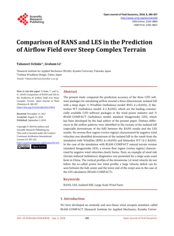
T. Uchida, G. Liare applied at the outflow boundary. On the ground surface, a non-slip boundary condition is imposed. For the simulation at Re ( Uinh/ν) 107, the numberof grid points is changed to 101 in the vertical direction, and the minimum vertical grid spacing in is set to Δzmin/h 4 10 7 according to the equation below(see Table 1):0.1 zmin h Re(1)In contrast to RIAM-COMPACT, WindSim uses RANS models. In thepresent study, the RNG k-ε RANS model is selected for the simulations. Refer to[23] for the numerical simulation methods used in WindSim and other detailsabout this software.3. Comparison of the Simulation Results from the Two CFDSoftware Packages (RIAM-COMPACT and WindSim) in theCase of a Three-Dimensional, Isolated Hill with a SteepSlope AngleFigure 5 shows the ensemble-averaged flow fields from the simulations withWindSim (turbulence model: RNG k-ε RANS). In neither of these simulations(a)(b)Figure 5. Wind velocity vectors and contour of streamwise (x) wind velocity(non-dimensional) on the x-z cross-section at the center of the span (y 0), ensemble-averaged flow field, WindSim (turbulence model: RNG k-ε RANS). (a) Re 5 104;(b) Re 5 107.DOI: 10.4236/ojfd.2018.83018291Open Journal of Fluid Dynamics
T. Uchida, G. Li(Re 5 104 and 5 107) did a reverse flow region (vortex region), in which thevalues of the streamwise wind velocity are negative, form downstream of theisolated hill. Instead, a potential-flow-like pattern formed in both simulations.Figure 6 shows instantaneous flow fields from the simulations withRIAM-COMPACT (turbulence model: standard Smagorinsky LES) (Re 5 104and 1 107). An examination of these simulation results reveals the clear presence of a reverse flow region (vortex region), in which the values of the streamwise wind velocity are negative, downstream of the isolated hill.(a)(b)Figure 6. Wind velocity vectors and contour of streamwise (x) wind velocity(non-dimensional) on the x-z cross-section at the center of the span (y 0), instantaneous flow field, RIAM-COMPACT (turbulence model: standard Smagorinsky LES). (a) Re 5 104, non-dimensional time 5.0; (b) Re 1 107, non-dimensional time 7.0.4. Overview of the Software Packages (RIAM-COMPACT andMeteodyn WT) and Numerical Simulation Set-Up in theCase of a Three-Dimensional, Isolated Hill with a SteepSlope AngleFor the present study, numerical simulations are conducted for high Reynoldsnumber flow around a three-dimensional, isolated hill with a steep slope angleusing RIAM-COMPACT, which is based on an LES turbulence model, andDOI: 10.4236/ojfd.2018.83018292Open Journal of Fluid Dynamics
T. Uchida, G. LiMeteodyn WT, which is based on a RANS turbulence model (see Table 2). Figure 7 shows the computational domain and grid used for the simulation withMeteodyn WT. An enlarged view of the computational grid in the vicinity of theisolated hill from the simulation with Meteodyn WT is shown in Figure 8. Figure 9 shows the method used to set the inflow profile in Meteodyn WT and theinflow profile generated for the present study.Figure 7. Computational domain and grid used for the simulation with Meteodyn WT,Re 107.Table 2. Comparison of numerical simulation methods, parameters, and settings betweenthe two software packages.CFD modelRIAM-COMPACTMeteodyn WTTurbulence modelStandardSmagorinsky LESk-L RANS(A single equation model)Atmospheric stratification(Atmospheric stability)Neutral atmosphereCoriolis forceNot consideredSurface roughnessNot considered(Smooth surface)Ground surfaceboundary conditionNon-slip condition(Three wind velocity componentsat the ground surface are zero.)Shape function of the isolated hill z (r)0.5h {1 cos(πr/a)} r (x2 y2)1/2, a 2hHeight of the isolated hill h100 (m)Reynolds number Re ( Uinh/ν)106Time step Δt10 h/Uin (s)107- 5Computational domain size19h (i) 18h (j) 8h (k)Number of computational grid points436 (i) 325 (j) 101 (k)436 (i) 325 (j) 37 (k)(Approx. 14.3 million points) (Approx. 5.2 million points)Streamwise (x) grid spacing (Δx)Spanwise (y) grid spacing (Δy)Vertical (z) grid spacing (Δz)DOI: 10.4236/ojfd.2018.83018Roughness length: 0.05(For the ground surface noton the isolated hill: 0.001)293(0.035 - 0.5) h(0.0001 - 0.6) h(0.005 - 1.2) hOpen Journal of Fluid Dynamics
T. Uchida, G. LiFigure 8. Enlarged view of the computational grid used in the simulations with MeteodynWT, Re 107.Figure 9. Method adopted in Meteodyn WT for setting the inflow profile and the inflowprofile generated for the present study.Since simulations for a flow with Re ( Uinh/ν) 107 were not feasible with theRIAM-COMPACT natural terrain version software because of the time step, anumerical wind simulation is performed at Re 106, which is an order of magnitude smaller than the flow simulated with Meteodyn WT. For this simulation,the number of grid points in the vertical direction is set to 101 (37 for the simulation with Meteodyn WT), and the minimum vertical spacing is set to Δzmin/h 10 4 based on the Equation (1) (Δzmin/h 5.0 10 3 for the simulation with Meteodyn WT, see Table 2). At the inflow boundary, an inflow profile which is almost identical to the inflow profile used for the simulation with Meteodyn(Figure 9) is used. Free-slip conditions are applied at the side and upper boundaries, and convective outflow conditions are applied at the outflow boundary.At the surfaces of the ground and the isolated hill, non-slip conditions are imposed. The time step is set to Δt 10 5 h/Uin (refer to Table 2).DOI: 10.4236/ojfd.2018.83018294Open Journal of Fluid Dynamics
T. Uchida, G. Li5. Comparison of the Simulation Results from the Two CFDSoftware Packages (RIAM-COMPACT and Meteodyn WT)in the Case of a Three-Dimensional, Isolated Hill with aSteep Slope AngleFigures 10-12 show results from the simulation with the Meteodyn WT software package (turbulence model: k-L RANS). These results (for a flow at Re 107) indicate that a reverse flow region (vortex region) characterized by negativevalues of wind velocity does not form downstream of the isolated hill, and a pattern resembling potential flow is present there. Figure 13 shows the results fromthe simulation with the RIAM-COMPACT natural terrain version softwarepackage (turbulence model: the standard Smagorinsky LES). Examinations ofthe results reveal that a reverse flow region (vortex region) characterized by negative values of wind velocities clearly exists downstream of the isolated hill in thesimulated flow at Re ( Uinh/ν) 106.Figure 10. Streamwise (x) wind velocity distribution at the center of the span (y 0), Meteodyn WT, k-LRANS, Re 107.Figure 11. Streamwise (x) turbulence intensity distribution at the center of the span (y 0), Meteodyn WT,k-L RANS, Re 107.DOI: 10.4236/ojfd.2018.83018295Open Journal of Fluid Dynamics
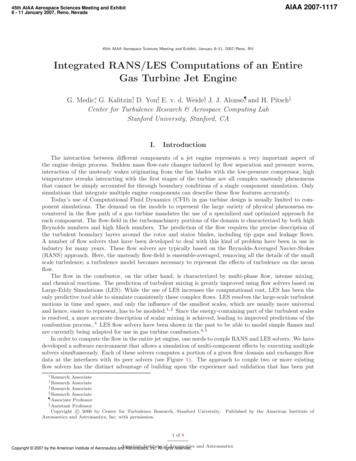
T. Uchida, G. LiFigure 12. Velocity vectors at the center of the span (y 0) in the vicinity of the isolatedhill, Meteodyn WT, k-L RANS model, Re 107.Figure 13. Streamwise (x) wind velocity distribution at the center of the span (y 0) inthe vicinity of the isolated hill, RIAM-COMPACT, standard Smagorinsky LES, Re 106.(a) Instantaneous flow field; (b) Time-averaged flow field.6. Comparison of the Simulation Results from the Two CFDSoftware Packages (RIAM-COMPACT and Meteodyn WT)in the Case of a Large-Scale Wind Farm in ChinaDougu wind farm is located in the city of Mengzi, Honghe prefecture, Yunnanprovince, China (see Figure 14). The wind farm started operation in 2012 and itconsists of 33 Mingyang wind turbines of rated capacity 1.5 MW. The turbineshave a hub height of 65 m with rotor diameter of 82.6 m. The turbines are located on top of a cliff and aligned in a north-south direction with elevationDOI: 10.4236/ojfd.2018.83018296Open Journal of Fluid Dynamics
T. Uchida, G. Li(a)(b)Figure 14. Large-scale wind farm investigated in the present study (Duogu Wind Farm).(a) Overall view; (b) Enlarged view. A group of 33 wind turbines are located above a steepescarpment.ranges from around 1850 to 2200 meters. The cliff has a height of around 900 mwith slopes exceeding 60 degrees in places. Aerial photos from Google Earth indicate vegetation is abundant at the bottom of the cliff but scarce along the cliffand in the vicinity of turbines. Since the start of operations, one of the wind turbines, turbine No.12 (T12) has experienced vibration problems. Wind farm operator Yunnan Huadian Dougu Wind Power Corporation (YUDWPC) suspected the vibration issue is related to wind conditions. In the present study, thesimulations are performed with RIAM-COMPACT, which is based on an LESturbulence model, and WindSim, which is based on a RANS turbulence model.The results from the simulations are compared.The vibration problem of turbine T12 was investigated by the operatorDOI: 10.4236/ojfd.2018.83018297Open J
analysis software has started being adopted in the wind power industry. In the previous study [16] [17] [18], the simulation results obtained from the RIAM-COMPACT software were compared to those from STAR-CCM , one of the leading commercially available CFD software packages. The


![FLOW TEMP. CONTROLLER [MASTER] (Cased) - mitsubishi-les.info](/img/6/im-ib-bh79d499h02-pac-if061-62-63b-e.jpg)