![FLOW TEMP. CONTROLLER [MASTER] (Cased) - Mitsubishi-les.info](/img/6/im-ib-bh79d499h02-pac-if061-62-63b-e.jpg)
Transcription
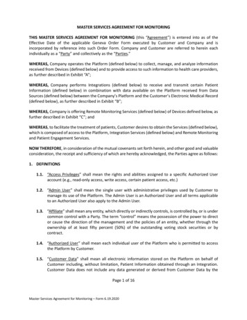
FLOW TEMP. CONTROLLER [MASTER] (Cased)PAC-IF061B-EPAC-IF062B-EPAC-IF063B-EFLOW TEMP. CONTROLLER [SLAVE] (Cased)PAC-SIF051B-EINSTALLATION MANUALFOR INSTALLERFor safe and correct use, read this manual thoroughly before installing the FTC unit.OPERATION MANUALFOR USERFor safe and correct use, please read this operation manual thoroughly before operating the FTC unit.English
Contents1.2.3.4.5.6.Safety precautions.2Installing the FTC unit.3System.5Electrical work.12Dip switch setting.27Before test run.327. Main remote controller operation. 338. Troubleshooting .499. Multiple outdoor units control.5410. Supplementary information .66Local application factors.67“FTC (Master)” is the abbreviation of “Flow Temperature Controller [Master]”, which is described as “FTC (Master)” in this manual.“FTC (Slave)” is the abbreviation of “Flow Temperature Controller [Slave]”, which is described as “FTC (Slave)” in this manual.In this manual, “FTC” that is not followed by “(Master)” or “(Slave)” means “FTC (Master and Slave)”.Mitsubishi Electric is not responsible for the failure of locally supplied parts.1. Safety precautionsFOR INSTALLERBefore installing the FTC unit, make sure you read all the “Safety precautions”.Please report to your supply authority or obtain their consent beforeconnecting this equipment to the power supply system.Warning:Precautions that must be observed to prevent injuries or death.Caution:Precautions that must be observed to prevent damage to the unit.Warning: The unit must not be installed by the user. Ask an installer or anauthorized technician to install the unit. If the unit is installed improperly,electric shock, or fire may be caused. For installation work, follow the instructions in the Installation Manual anduse tools and pipe components specifically made for use with refrigerantspecified in the outdoor unit installation manual. The unit must be installed according to the instructions in order to minimize the risk of damage by earthquakes, typhoons, or strong winds.Improperly installed units may fall down and cause damage or injuries. The unit must be securely installed on a structure that can sustain itsweight. If the unit is mounted on an unstable structure, it may fall downand cause damage or injuries. All electric work must be performed by a qualified technician according tolocal regulations and the instructions given in this manual. The unit mustbe powered by dedicated power lines and the correct voltage and circuitbreakers must be used. Power lines with insufficient capacity or incorrectelectrical work may result in electric shock or fire.After installation, perform the test run to ensure normal operation. Then explainto your customer the “Safety Precautions” *1, use, and maintenance of the unitbased on the information in this manual. This manual must be given to the user.This manual must always be kept by the actual users.*1 “Safety Precautions” for user is indicated on page 33.: This indicates a part which must be grounded.Warning:Carefully read the labels attached to the unit. O nly the specified cables can be used for wiring. Connections must bemade securely without tension on the terminals. If cables are connectedor installed improperly, it may result in overheating or fire. Terminal block cover panel of the unit must be firmly fixed. If the coverpanel is mounted improperly, dust and moisture may enter the unit, and itmay cause electric shock or fire. Make sure to use accessories authorized by Mitsubishi Electric and askan installer or an authorized technician to install them. If accessories areimproperly installed, it may cause electric shock, or fire. Do not remodel the unit. Consult an installer for repairs. If alterations orrepairs are not performed correctly, it may cause electric shock or fire. The user should never attempt to repair the unit or transfer it to anotherlocation. If the unit is installed improperly, it may cause electric shock orfire. If the FTC unit needs to be repaired or moved, ask an installer or anauthorized technician. During installing a heat pump system, keep water from splashing on theFTC unit. When installing sensors and parts, do not expose the terminals.1.1 Before installation (Environment)Caution: Do not install the FTC unit in outdoor location as it is designed for indoorinstallation only. Otherwise electric shock or breakdown may be causedby water, wind or dust. Do not use the unit in an unusual environment. If the FTC unit is installedor exposed to steam, volatile oil (including machine oil), or sulfuric gas, orexposed to briny air, the internal parts can be damaged. Do not install the unit where combustible gases may leak, be produced,flow, or accumulate. If combustible gas accumulates around the unit, itmay cause fire or explosion. When installing the unit in a hospital or in a building where communications equipment are installed, you may need to take measures to preventnoise and electronic interference. Inverters, home appliances, highfrequency medical equipment, and radio communications equipment cancause the FTC unit to malfunction or to breakdown. At the same time, thenoise and electric interference from the FTC unit may disturb the properoperation of nearby medical equipment, and communications equipment.1.2 Before installation or relocationCaution: Be very careful when moving the units. Do not hold the packaging bands.Wear protective gloves to unpack and to move the units, in order to avoidinjury to your hands. Be sure to safely dispose of the packaging materials. Packaging materials, such as nails and other metal or wooden parts may cause injuries. Do not wash the FTC unit. You may receive an electric shock.1.3 Before electric workCaution: B e sure to install a circuit breaker. If it is not installed, there may be arisk to get an electric shock. For the power lines, use standard cables of sufficient capacity. Otherwise, it may cause a short circuit, overheating, or fire. When installing the power lines, do not apply tension to the cables. Thecables may be cut or overheated resulting in a fire.2 M ake sure to ground the unit. Do not connect the ground wire to gas orwater pipes, lightning rods, or telephone grounding lines. If the unit isnot properly grounded, there may be a risk to get an electric shock. Make sure to use circuit breakers (ground fault interrupter, isolatingswitch ( B fuse), and molded case circuit breaker) with the specified capacity. If the circuit breaker capacity is larger than the specified capacity,breakdown or fire may result.
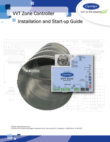
1. Safety precautions1.4 Before starting the test runCaution: T urn on the main power switch of the outdoor unit more than 12 hoursbefore starting operation. Starting operation immediately after turning onthe power switch can severely damage the internal parts. Keep the mainpower switch turned on during the operation period. In heating mode, to avoid the heat emitters being damaged by excessively hot water, set the target flow temperature to a minimum of 2ºC belowthe maximum allowable temperature of all the heat emitters. For Zone2,set the target flow temperature to a minimum of 5ºC below the maximumallowable flow temperature of all the heat emitters in Zone2 circuit. B efore starting operation, check that all protective parts are correctly installed. Make sure not to get injured by touching high voltage parts. Do not touch any switch with wet hands. There may be a risk to get anelectric shock. After stopping operation, make sure to wait at least 5 minutes beforeturning off the main power. Otherwise, it may cause breakdown.1.5 Electric booster and immersion heatersWarning: F TC has signal outputs for heaters however it can not isolate power tothem in the event of overheating. All electrical heaters used on the watercircuit must have.a) A thermostat to prevent overheating.b) A non-self resetting thermal mechanism to prevent overheating.Abbreviations and glossaryAbbreviations/WordDescriptionAmbient temperatureFreeze stat. functionASHP/HPCOPCylinder unitHydroboxDeltaTDHW modeFlow temperatureFTC (Master)FTC (Slave)Compensation curve modeHeating modeCooling modeLegionellaLP modePackaged modelSplit modelTRVThe outdoor temperatureHeating to prevent water pipes freezingAir source heat pumpCoefficient of performance the efficiency of the heat pumpIndoor unvented DHW tank and component plumbing partsIndoor unit housing the component plumbing parts (NO DHW tank)Difference in temperature between two system locations.Domestic hot water heating mode for showers, sinks, etcTemperature at which water is delivered to the primary circuitFlow temperature controller, the circuit board in charge of controlling the system, master board for multiple outdoor units controlSlave board for multiple outdoor units controlSpace heating incorporating outdoor temperature compensationSpace heating through radiators or under floor heatingSpace cooling through radiators or under floor coolingBacteria potentially found in plumbing, showers and water tanks that may cause Legionnaires diseaseLegionella prevention mode – a function on systems with tanks to prevent the growth of legionella bacteriumPlate heat exchanger (Refrigerant - Water) in the outdoor heat pump unitPlate heat exchanger (Refrigerant - Water) in the indoor unitThermostatic radiator valve – a valve on the entrance or exit of the radiator panel controlling the heat output2. Installing the FTC unit12.1. Check the parts (Fig. 2.1.1)The FTC unit should be supplied with the following parts.MasterSlavePart name122,3,45345676FTC (master) unit/FTC (slave) unitQ’tyWiringdiagram PAC- PAC- PAC- PACsymbol IF061 IF062 IF063 SIF0511111Liquid refrigerant temp. thermistorTH21 1(Lead wire: 5m/Red, Connector: 3p/Yellow)Flow water temp. and Return watertemp. thermistor1111(Lead wire: Gray (Flow water temp.),THW1/2(1.1m/(5m/5m) (5m/5m)(5m/5m)Black(Return water temp.),1.2m)Connector: 4p/Red)Tank temp. thermistorTHW5 1 (Lead wire: 1.8m/Gray, connector: 2p/white)Main remote controller cable (10 m)1111Main remote controller111 SD memory card11117 Fig. 2.1.1 3
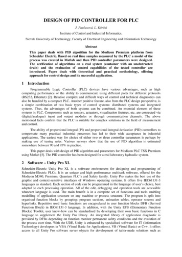
2. Installing the FTC unit2.2. Choosing the FTC unit installation locationD Do not install the FTC units outdoors as it is designed for indoor installationonly. (The FTC circuit board and casing are not waterproof.) Avoid locations where the unit is exposed to direct sunlight or other sources ofheat. Select a location where easy wiring access to the power source is available. Avoid locations where combustible gases may leak, be produced, flow, or accumulate. Select a level location that can bear the weight and vibration of the unit. Avoid locations where the unit is exposed to oil, steam, or sulfuric gas. Do not install in location that is hot or humid for long periods of time.BA Fig. 2.3.1 2.3. Installing the FTC unit (Fig. 2.3.1, 2.3.2, 2.3.3, 2.3.4)1. R emove 2 screws (A Screw) from FTC unit and remove the cover. (See Fig.2.3.4)2. Install the 4 screws (locally supplied) in the 4 holes (C Hole).w To prevent the unit from falling off the wall, select the appropriate screws (locally supplied) and secure the base horizontally to the appropriate wall location.(See Fig. 2.3.2)Top30 mm or moreA ScrewC Hole for installationCoverNote: Do not remove the screws D as the screws are the component parts of thecover and are not used for the installation of cover.WallBaseB CoverD wable ambient temperatureAllowable ambient humidityWeightOptional extras Wireless Remote Controller Wireless Receiver Remote sensor Fig. 2.3.2 4.0 kg4.4 kg1.9 kg0 to 35 C80% RH or lessPAR-WT50R-EPAR-WR51R-EPAC-SE41TS-EService 1CC72.4C22(12.5)Ø5207288.839336842212.5C Unit: mm FTC (Slave) unit 10 FTC (Master) unit CC2-ELECT WIRE INLETWhen installed on a wall: Lower side5-ELECT WIRE INLETWhen installed on a wall: Lower sideRemove the 2 screws A(control box cover screws).BottomPull the cover to thefront and remove it.Slide the control box coveruntil the bottom of the covercomes into contact with thebottom of the control box.CoverTop14Base Fig. 2.3.3 BottomFrontTop2 Fig. 2.3.4 BottomTop3
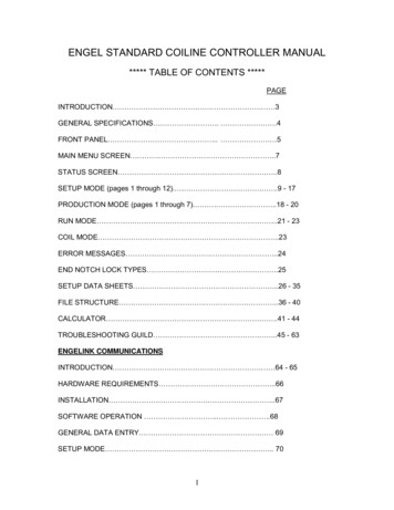
3. SystemThe FTC (Master) is designed for use with a number of heat pump systems. Please refer to the following table to find the relevant installation information for your system.For multiple outdoor units control with FTC (Slave), see section 9.3.1 First step (Electrical work)Power suppliesReferencesectionSystem diagramFTC (Master) powered via outdoor unit4.14.2Wireless receiver(Option)FTC (Master)Outdoor unitWireless Remote controller(Option)Main remote controllerFTC (Master) powered by independentsource4.14.2Wireless receiver(Option)FTC (Master)Outdoor unitWireless Remote controller(Option)Main remote controller3.2 Second step (Outdoor unit type)Outdoor unit typeSystem diagramSplitReferencesectionThermistorTH2: Liquid refrigerant temp.4.45.2—4.45.2Heat exchangerOutdoor unitTH2PackagedHeat exchangerOutdoor unit* PAC-IF062/063B-E is not available for Split-type s
Choose that with a maximum allowable temperature of 55ºC. (3) When the SD memory card is a miniSD, miniSDHC, microSD, or micro SDHC memory card, use an SD memory card converter adapter. (4) Before writing to the SD memory card, release the write-protect switch.