Transcription
Proceedings of the National Seminar & Exhibitionon Non-Destructive EvaluationNDE 2011, December 8-10, 2011STUDY AND COMPARISON OF DIFFERENT FABRICATION AND NDTREQUIREMENTS FOR PRESSURE VESSEL, BOILER, PIPING, STRUCTURE &NUCLEAR COMPONENT MANUFACTURING WITH RESPECT TO VARIOUS CODES &STANDARDSKamal H.Dhandha1, A.D.Bhathena2, Manas Ghosh3 and Dr.Sanjay Soman431,2Modular Fabrication Facility, E & C Division;Heavy Engineering Division, Larsen & Toubro Limited, Hazira Manufacturing Complex, Surat, Gujarat, INDIA4Metallurgical & Materials Engineering Department, Faculty of Technology & Engineering,The Maharaja Sayajirao University of Baroda, Vadodara, Gujarat, INDIAABSTRACTNon-Destructive Testing (NDT) is the application of measurement techniques in order to identify damage andirregularities in materials. Different non-destructive examination methods are called for at various stages viz. InManufacture Inspection (IMI), Pre-Service Inspection (PSI) and In-Service Inspection (ISI). The presence of flaws incritical components may result in the integrity of such systems being compromised and increase the likelihood offailure. Correct selection and application of an NDT technique can provide confidence that a component or piece ofplant does not contain defects of the type which the technique was capable of detecting. The capability of an NDTtechnique to detect and size specified defects can be assessed by the gathering of evidence based on physical reasoning,theoretical modelling, experimental work and previously published work. In this case NDT is just one of a number ofquality control activities aimed at producing a component or piece of plant to a particular specification. The NonDestructive Testing methods to be used and the maximum size of flaws which can be tolerated are given in the flawacceptance clauses in various codes. In this liberalized and global market, it is necessary for an industry to manufactureproduct (viz. pressure vessels, boilers, piping, structure & nuclear components etc.) according to various national/international codes & standards and hence, it is necessary to know, understand & interpret various acceptance criteria.Study of this acceptance standards & comparison between them is the need for today’s Fabrication industries aspiresto be globalized.Keywords : Integrity, Flaws, Interpretation, Reliability, GlobalizeINTRODUCTIONTHEORYIn order to control the welding work and to have uniformityin the material selection, welding processes, testing andinspection, standards have been evolved based on longexperience and critical experimentation. These codes are givenfor different categories of work such as Boiler, Pressurevessels, Pipe lines, Oil storage tanks, Structural works etc.Conformity to the particular norm or code laid down for eachwork is required for satisfactory functioning of the weldedjoints.Codes & Standards are the authentic documents, usage ofwhich give a products / services of National / Internationalstandards with respect to quality, reliability etc. also this giveuniformity of various manufacture to manufacture the product/ service. Codes are mandatory, where as Standards arerecommended and reference documents.A comprehensive knowledge about acceptance standards ofvarious NDT methods according to various manufacturingcodes & standards is mandatory for Welding/QA/QC Engineerstoday.Acceptance Criteria:Limit of shape, size and position of discontinuities acceptablewithin the context of the specific design requirements.Many codes are having common acceptance criteria. Therefore,it become unambiguous for inspector to identify the defects,
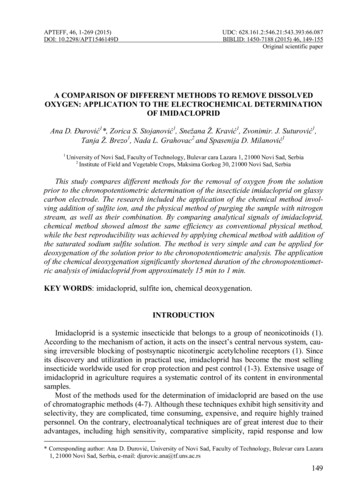
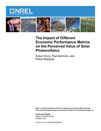
388Kamal H.Dhandha et.al : Proceedings of the National Seminar & Exhibition on Non-Destructive Evaluationwhich exceeds acceptance criteria irrespective of availabilityof acceptance codes if abstract of it has been kept tip of thetongue. In some codes additional requirements are specifiedbased on severity of application.ACCEPTANCE CRITERIA FOR MAJOR NDEMETHODSAcceptance criteria for Ultrasonic ExaminationAs per ASME Sec.VIII Div.1, Div.2, Sec.I, Sec.III NB, ASMEB31.1, ASME B31.3 ((b) only), are(a) Indications characterized as cracks, lack of fusion, orincomplete penetration are unacceptable regardless oflength.(b) Other imperfections are unacceptable if the indicationsexceed the reference level amplitude and have lengthswhich exceed:(1) 1D 4 in. (6 mm) for t up to 3D4 in. (19 mm);(2) 1D3t for t from 3D4 in. to 2¼ in. (19 mm to 57 mm);(3) 3D4 in. (19 mm) for t over 2¼ in. (57 mm).(a)&(b) Same as Ultrasonic Examination(c) any group of aligned indications that have an aggregatelength greater than t in a length of 12t, except when thedistance between the successive imperfections exceeds6L where L is the length of the longest imperfection inthe group;(d) rounded indications in excess of that specified by theacceptance standards given in as below.Rounded indicationsRelevant IndicationsOnly those rounded indications which exceed the followingdimensions shall be considered relevant.(1)1D10t for t less than 1D8 in. (3 mm)(2)1D64 in. for t from 1D8 in. to 1D4 in. (3 mm to 6mm), incl.(3)1D32 in. for t greater than 1D4 in. to 2 in. (6 mmto 50 mm), incl.(4) 1D16 in. for t greater than 2 in. (50 mm)Acceptance criteria for Radiographic ExaminationAs per ASME Sec.VIII Div.1, Div.2, Sec.I, Sec.III NB, ASMEB31.1, API620 & API650 areMaximum Size of Rounded Indication.The maximum permissible size of any indication shall be 1D4t, or 5D32 in. (4 mm), whichever is smaller; except that anCOMPARISON BETWEEN ACCEPTANCE CRITERIA FOR VISUAL EXAMINATION OF WIDELY USED CODESTable 1 : Comparison between Acceptance standard for AWS D1.1, ASME Sec.VIII Div.1 & ASME B31.3
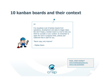
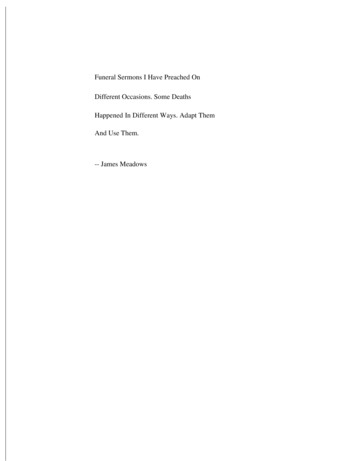
Table 2 : Comparison between Acceptance standard for ISO 5817, ASME Sec.VIII Div.1 & AWS D1.1NDE 2011, December 8-10, 2011389
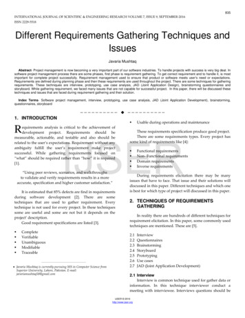
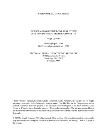
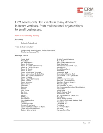
COMPARISON BETWEEN ACCEPTANCE CRITERIA FOR RADIOGRAPHIC EXAMINATION OF WIDELY USED CODES390Kamal H.Dhandha et.al : Proceedings of the National Seminar & Exhibition on Non-Destructive Evaluation
NDE 2011, December 8-10, 2011391isolated indication separated from an adjacent indication by 1in. (25 mm) or more may be 1D3t, or 1D4 in. (6 mm),whichever is less. For t greater than 2 in. (50 mm) the maximumpermissible size of an isolated indication shall be increased to3D8 in. (10 mm).REFERENCESAligned Rounded Indications. Aligned rounded indicationsare acceptable when the summation of the diameters of theindications is less than t in a length of 12t.2.ASME Sec. VIII Boiler & Pressure Vessel Code:2010Div.1 Rules for Construction of Pressure Vessels, Div.2Alternative Rules Rules For Construction Of PressureVesselsAWS D1.1/D1.1M:2010 Structural Welding Code—Steel3.4.ASME B31.1-2004 Power PipingASME B31.3-2006 Process PipingClustered Indications. The illustrations for clusteredindications show up to four times as many indications in alocal area, as that shown in the illustrations for randomindications. The length of an acceptable cluster shall not exceedthe lesser of 1 in. (25 mm) or 2t. Where more than one clusteris present, the sum of the lengths of the clusters shall not exceed1 in. (25 mm) in a 6 in. (150 mm) length weld.5.ASME B31.4-2002 Pipeline Transportation Systems forLiquid Hydrocarbons and Other LiquidsASME B31.8-2007 Gas Transportation and DistributionPiping SystemsRounded Indication Charts – relevant rounded indicationscharacterized as imperfections shall not exceed those shownin Figures, which illustrate various types of assorted, randomlydispersed and clustered rounded indications for different weldthicknesses greater than 3 mm (1/8 in).Acceptance criteria for Liquid Penetrant ExaminationAs per ASME Sec.VIII Div.1 (a) only), Div.2 (a) &b) only),Sec.I (a) only) API 620 & API 650 (a) only), Sec.III NB, ASMEB31.1, are(a)Only indications with major dimensions greater than1D16 in. (1.5 mm) (2 mm in ASME B31.1) shall beconsidered relevant.All surfaces to be examined shall be free of:(1) relevant linear indications;(2) relevant rounded indications greater than 3D16 in.(5mm);(3) four or more relevant rounded indications in a lineseparated by 1D16 in. (1.5 mm) (2 mm in ASMEB31.1) or less (edge to edge).(b) Crack like indications detected, irrespective of surfaceconditions, are unacceptable.(c) ten or more rounded indications in any 6 sq. in. (3870mm2) of surface with the major dimension of this areanot to exceed 6 in. (150 mm) with the area taken in themost unfavorable location relative to the indications beingevaluated.Acceptance criteria for Magnetic ParticleExaminationAs per ASME Sec.VIII Div.1(a) only, Div.2 (a) &b) only),Sec.I (a) only) API 620 & API 650 (a) only), Sec.III NB, ASMEB31.1 (a) only), are same as for Liquid Penetrant Examination1.6.7.8.API 1104 Welding of Pipelines and Related Facilities,20th Edition, Nov 2005ASME Sec.III Division 1 – Subsection NB:2007 Rulesfor Construction of Nuclear Facility Components, Class1 Components9.ASME Sec.I:2010 Rules for Construction of PowerBoilers10. API Specification 2B Specification for the Fabricationof Structural Steel Pipe, 6th Edition, July 200111. API Specification 5L Specification for Line Pipe, 43rdEdition, March 200412. API Recommended Practice 2A-WSD RecommendedPractice for Planning, Designing and Constructing FixedOffshore Platforms-Working Stress Design, 21st Edition,December 200013. API Recommended Practice 2X Recommended Practicefor Ultrasonic and Magnetic Examination of OffshoreStructural Fabrication and Guidelines for Qualificationof Technicians, 200414. ASME Sec.II Part A:2010 Materials - Ferrous MaterialSpecifications15. NBIC National Board Inspection Code : 200716. API 650 Welded Steel Tanks for Oil Storage, TenthEdition, November 199817. API 620 Design and Construction of Large, Welded,Low-pressure Storage Tanks, Tenth Edition, February200218. ISO 3834:2005 Quality requirements for fusion weldingof metallic materials, Benefits and ImplementationRevision 1 – 1 August 2008, WTIA19. ISO 5817-2003 Welding-fusion welded joints in Steel,Nickel, Titanium and their alloys (beam weldingexcluded) – Quality Levels for Imperfections20. ISO 6520-1:2007 Welding and allied processes Classification of geometric imperfections in metallicmaterials - Part 1: Fusion welding21. EN ISO 13920 General tolerances for weldedconstructions, Tolerances for lengths, angles, shape andposition
392Kamal H.Dhandha et.al : Proceedings of the National Seminar & Exhibition on Non-Destructive Evaluation22. BS EN 12517-1:2006 Non-destructive testing of weldsPart 1: Evaluation of welded joints in steel, nickel,titanium and their alloys by radiography – Acceptancelevels23. PD 5500:2009 Specification for Unfired fusion weldedpressure vessels24. AD 2000-Merkblatt HP 5/3 Manufacture and testing ofjoints, Non-destructive testing of welded joints, January2002 edition25. BS 5289:1976 (1983) Code of Practice. Visual inspectionof fusion welded joints26. BS 970:1997 Non-destructive examination of fusionwelds – Visual examination27. BS 5950-2:2001 Structural use of steel work in building– Part 2:Specification for materials, fabrication anderection – Rolled and welded sections28. IS 2825:1969 Code for Unfired Pressure vessels, BIS,New Delhi29. IS 7215:1974 Tolerances for Fabrication of SteelStructures, BIS, New Delhi30. IS 803-1976 Code of Practice for Design, Fabricationand Erection of Vertical Mild Steel Cylindrical WeldedOil Storage Tanks, BIS, New Delhi31. NORSOK Standard M-101, Structural Steel Fabrication,Rev.4, Dec.200032. PFI Standard ES-3,2000 Fabricating Tolerances, PipeFabrication Institute
thicknesses greater than 3 mm (1/8 in). Acceptance criteria for Liquid Penetrant Examination As per ASME Sec.VIII Div.1 (a) only), Div.2 (a) &b) only), Sec.I (a) only) API 620 & API 650 (a) only), Sec.III NB, ASME B31.1, are (a) Only indications with major dimensions greater than 1D16 in. (1.5 mm) (2 mm in ASME B31.1) shall be considered relevant.