Transcription
Setup Manual and Programming ReferenceRGA Ethernet AdapterStanford Research SystemsRevision 1.05 (11/2010)
CertificationStanford Research Systems certifies that this product met its published specifications at the timeof shipment.WarrantyThis Stanford Research Systems product is warranted against defects in materials andworkmanship for a period of one (1) year from the date of shipment.ServiceFor warranty service or repair, this product must be returned to a Stanford Research Systemsauthorized service facility. Contact Stanford Research Systems or an authorized representativebefore returning this product for repair.Information in this document is subject to change without notice.Copyright Stanford Research Systems, Inc., 2010. All rights reserved.Stanford Research Systems, Inc.1290-C Reamwood AvenueSunnyvale, California 94089www.thinksrs.comPrinted in U.S.A.RGA Ethernet Adapter
3ContentsContents 3Unpacking 4Checklist 4Package Contents 4Specifications 5Chapter 1 Getting Started 7Chapter 2 Configuration 9REA Configuration Methods 9Software Installation and Quick Cable Check 10Chapter 3 REA Setup Utility 13Configuration using the REASetupUtility 14Manual Static IP Setup 14Automatic IP Setup Using DHCP 15Troubleshooting 16Login Parameter Modification 16Configuration Test 18Connecting to the RGA Through Ethernet 19Connection from ‘REASetupUtility’ 19Connection from within the RGA Software 19Chapter 4 Remote Programming and Errors 21Introduction to Remote Commands 21Communication via Ethernet 21Communication via USB 21Command Format 21Command Syntax 22Query Commands 23Error Query Commands 23Parameter Setting Commands 23Error Codes 25Chapter 5 Configuration via USB 27USB Driver Installation 27Manual IP Configuration over USB 27RGA Ethernet Adapter
4UnpackingChecklist Open the box and inspect all components of the RGA Ethernet Adapter (REA).Report any damage to Stanford Research Systems immediately.Compare the contents of the shipping boxes against your original order and thechecklist below. Report any discrepancies to Stanford Research Systemsimmediately.Package Contents RGA Ethernet Adapter5V Power supply & 6’ USB cable (type A male to type B male)3’ RS232 cable14’ straight-through Ethernet cable (CAT5e or comparable)1 CD (RGA software & REA setup software, USB driver, electronic Manuals)REA manualCover for RGA (Optional)RGA Ethernet Adapter
5SpecificationsInterface :Ethernet interface10/100 BASE-T (RJ-45) female connectorUSB interfaceUSB type B female connectorUSB 2.0 compliant full-speed deviceEnumeration to communication device class (USB CDC)Internet Protocols supportedProtocolsARP, IP, ICMP, UDP, TCP, Telnet, DHCP, FTP,SICP (SRS Internet Configuration Protocol)GeneralPower requirement5 Vdc , 0.5 Amp through USB type B female connectorDimensions10.7 cm H x 11.2 cm W x 3.0 cm D(4.2 in H x 4.4 in W x 1.2 in D)Weight0.2 kg (0.1 lb. )RGA Ethernet Adapter
6RGA Ethernet Adapter
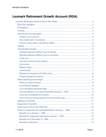
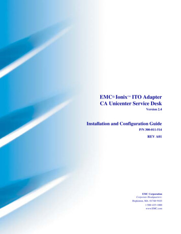
7Chapter 1Getting StartedThe RGA Ethernet Adapter (REA) allows a host PC to communicate with an SRS RGAover Ethernet. The adapter converts between the RS232 port of the SRS RGA (baud rateof 28.8k) and Ethernet 10/100 Base-T.As shown in the figure below, the REA has 3 connectors: Serial DB9 male to SRS RGA,an RJ45 to your network (with link speed and activity indicators), and a USB/B for power(and optional setup). The serial number and MAC address of the REA can be found onthe back of the REA. A push button labeled IP SET on the back of the REA must bedepressed when power is applied to put the REA into setup mode.Figure 1-1 Front and back panelsFive LED indicators on the top cover of the REA indicate activity and status.LED indicatorsActivityPOWER (Red)ON power on, OFF power offETHERNET (Green)ON in “Ready for IP setup” stateOFF no data activityFast Blinking data activity1 Hz blinking DHCP running4 Hz blinking DHCP failedUSB (Green)Blinking data activity, OFF no activityRGA Tx (Yellow)Blinking data from RGA, OFF no activityRGA Rx (Yellow)Blinking data to RGA, OFF no activityTable 1-1 LED indicatorsRGA Ethernet Adapter
8Getting StartedRGA Ethernet AdapterChapter 1
9Chapter 2ConfigurationREA Configuration MethodsThe network configuration can be performed in three ways: Automatically using yournetwork’s Dynamic Host Configuration Protocol (DHCP) server, manually for a static IPover Ethernet, or manually over USB. Each method will be described in detail. The RGAsoftware works equally well with the REA in static or dynamic IP modes.SoftwareManual Static IPover EthernetDHCP overEthernetManual Static IPover l communicationsoftwarePrerequisite Details of IP address, DHCP serverSubnet mask,GatewayDetails of IP address,Subnet mask,GatewayProsEasiestBest for programmersDHCP server maynot be available onyour network.Unforgiving, crypticConsStraight forwardmenus guide youthrough the processTable 2-1 Comparison of configuration methodsMost users will prefer to use the REASetupUtility over Ethernet as it displaysinformation about other REA units that may be present on the network and guides theuser through the setup procedure. These users should:1. perform the Software Installation and Quick Cable Check (instructions follow)2. Use the REASetupUtility to configure the adapter (Chapter 3)Users interested in configuring the REA manually over USB should:1. perform the Software Installation and Quick Cable Check (instructions follow)2. Read Chapter 4 - Remote Programming3. Follow the instructions in Chapter 5 to install the optional USB driver andmanually configure the REARGA Ethernet Adapter
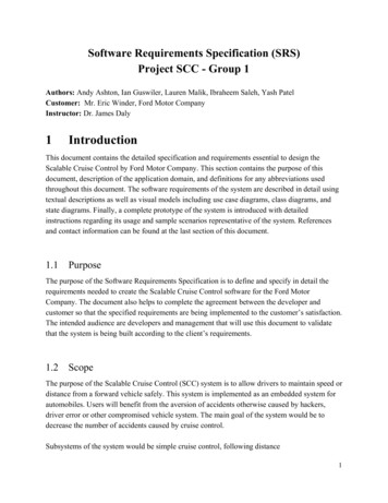
10REA ConfigurationChapter 2Software Installation and Quick Cable CheckSetup of the REA begins with installation of the software and a quick check of thecabling and power:1. Install the RGA Windows softwareInstall the RGA software from the CD. Make sure the “Setup REA Utility” install optionis checked (see screenshot below).You must install the software with administrator account privileges because the RGAprogram needs full "write" privileges.Figure 2-2 Choose ‘Setup REA Utility’ in the RGA installer options2. Apply power to the REAPower up the REA by connecting the REA to the USB power adapter. Initially all theLED’s are on for one second after which only the POWER LED should be on.3. Connect to the networkConnect an Ethernet cable between the RJ45 connector on the REA and your network.The green LED on the RJ45 connector should be on or flashing.RGA Ethernet Adapter
Chapter 2REA Configuration11RJ45 connector frontGreen LEDYellow LEDFigure 2-3 LED indicators on the RJ45 Ethernet portGreen LED for activity (ON Linked, Blinking Active, OFF Disconnected)Yellow LED for speed (ON 100 BASE-T, OFF 10 BASE-T)RGA Ethernet Adapter
12REA ConfigurationRGA Ethernet AdapterChapter 2
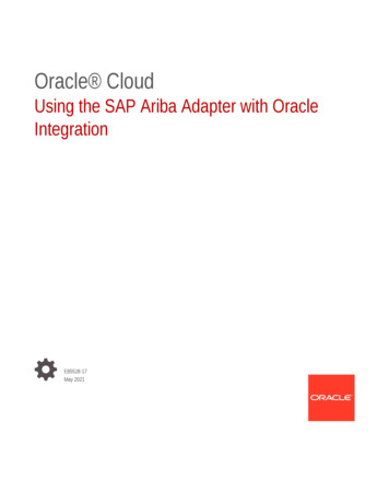
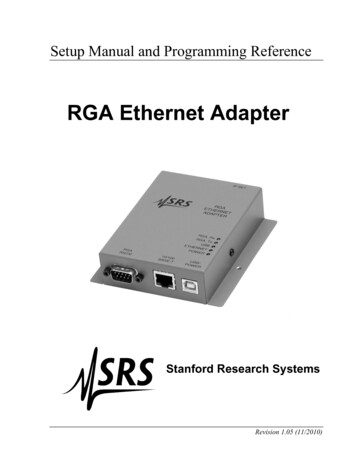
13Chapter 3REA Setup UtilitySRS provides the ‘REASetupUtility’ software for Ethernet configuration of the REA.When the ‘Search’ button is clicked, the software will collect information from all REAunits that are currently connected to your local area network (LAN). If no information isshown after the search, it could be due to firewall software running on your computer. Ifthis is the case, temporarily disable the firewall and try again.Figure 3-1 REASetupUtility window after successful ‘Search'In the window, the Status column indicates the status of each REA on your LAN. Thefollowing table summarizes the possible states of the REA after the ‘Search’ button isclicked.As shown above, all adapters on the same network will be visible and can be setup from asingle computer.RGA Ethernet Adapter
14REA Setup UtilityChapter 3StatusMeaningReady for SetupREA is in IP setup mode and waiting to be configured.AvailableREA is ready to use with the RGA software.Out of SubnetThe IP address and the subnet mask are not on thesame network as your computer. This will prevent theRGA software from connecting to the REA from yourcomputer. If you intend to operate the REA on adifferent network from the one your computer iscurrently on, this may be correct. Otherwise, ask yournetwork administrator to review the network values (IPaddress, subnet, and gateway).IP Change FailedThe last IP setting failed (no change occurs). Try againwith a different IP address.IP ConflictThere is another device using the same IP addressonline when REA is powered on. If this happens, theETHERNET LED will blink very fast (4 times eachsecond) for 3 minutes. Changing the IP address on theREA or the other device is necessary. If the IP addressof the other device is changed, turn REA off and on toget the ‘Available’ status.OccupiedREA is already connected to another host computer.DHCP RunningDHCP is in progress.DHCP FailedThe DHCP negotiation has failed. This is usuallybecause there is no DHCP server active on yournetwork. It might also be due to a network securitymeasure such as MAC filtering. Ask you networkadministrator for help.Table 3-1 REA states after ‘Search’Configuration using the REASetupUtilityAfter choosing the configuration method based on the information in Table 2-1, youshould follow either the manual or the automatic procedure. Do not do both.Manual Static IP Setup1. Fill out the table below with the network values obtained from your networkadministrator:IP addressSubnet maskGateway2. Power up the REA and make sure all the cables are connected.RGA Ethernet Adapter
Chapter 3REA Setup Utility153. Disable any anti-virus software or give permission to the ‘REASetupUtility’software. Then start ‘REASetupUtility’ from Start All Programs SRS RGA.4. Reboot the REA into IP setup mode by following these steps:i. Disconnect the USB power cable from the USB port of the REA.ii. While pushing the IP SET switch, reconnect the USB power cable.5. The green ETHERNET LED on top of the REA should be on. If not, repeat step 4above. The REA will remain in the ‘Ready for Setup’ state for 5 minutes. If setupdoes not occur during this time, the REA will return to its previous state.6. In the ‘REASetupUtility’ software, click the ‘Search button.7. Select the row with the ‘Ready for Setup’ status, then click the ‘Setup’ button (seeFigure 3-1). The following dialog box will appear.Figure 3-2 Network setup dialog box8. In the pop-up dialog, type in the network values from step 1. To avoid confusion,give the REA a descriptive name here. Then click ‘Set’.9. If the setup is successful, the status should now show ‘Available’ in the REASetupwindow and the green ETHERNET LED on top of the REA will be off.10. The REA is now ready to use. See page 16 - Login Parameter Modification to changethe user name and password of the REA.Automatic IP Setup Using DHCPIf there is a DHCP server on your network, the DHCP function in the REASetupUtilityprogram will automatically configure the IP address, subnet, and gateway. After the REAis set by this function, it will automatically use DHCP to obtain its network addresseswhenever it powers on. If DHCP is no longer desired, configure the network valuesRGA Ethernet Adapter
16REA Setup UtilityChapter 3manually (instructions above). After verifying with your network administrator that yournetwork has a DHCP server, follow these steps:1. Skip step 1 of the manual setting procedure above. Follow steps 2 through 7 until youreach the setup dialog box (Figure 3-2) for the selected REA.2. In the setup dialog box, mark ‘Obtain IP automatically by DHCP’. The manual editsection will be dimmed. Click the ‘Set’ button.3. The REA will attempt DHCP negotiation for up to 90 seconds. During this process,the ETHERNET LED on top of the REA will blink at 1 Hz.4. Upon successful completion of the DHCP negotiation, the ETHERNET LED willturn off. Clicking the ‘Search’ button again will display a status of “Available”.5. The REA is now ready to use. To avoid confusion, it is a good idea to give the REA adescriptive name. See below - Login Parameter Modification to change the username, password and device name of the REA.TroubleshootingIf there is a conflict with the IP address (already assigned to another device or computeron your network) during manual IP setup, the “Failed to Change” status will appear afterclicking the ‘Set’ button.“Out of Subnet” status appears when the host computer and the REA do not have thesame network prefix in their IP address according to the subnet mask. (The networkaddress of the host PC is listed in the bottom right of the window.) In order to use theREA on the same LAN, the network prefix portion of the IP address should match thecomputer. If the REA will be used on a different network, it is fine to be out of subnet.If the DHCP setup fails, the ETHERNET LED will blink at 4 Hz. Clicking the ‘Search’button of the REASetupUtility program will confirm the failure by showing “DHCPFailed” in the status column.Login Parameter ModificationAfter the IP setup of the REA completes successfully, it is a good idea to modify the Username and Password.1. Select an REA whose status is ‘Available’.2. Then click the ‘Modify’ button.3. The Modify dialog box will appear as shown below (Figure 3-3).RGA Ethernet Adapter
Chapter 3REA Setup Utility17Figure 3-3 Modify User Name, Password and Device Name dialog box4. Login using the default User name and Password.Default Username: AdminDefault Password: AdminA successful login makes the ‘Edit’ section active.5. Type in a new Username, Password and Device Name.New Username:New Password:6. Click ‘Set’.7. If the modification is successful, close the dialog box by clicking ‘Close’.If the User Name and/or Password settings are lost, they can be reset to the default valuesin the Network Setup dialog box (Figure 3-2). By marking ‘Reset Name and Password’and then clicking ‘Set’, these parameters are reset to the default. This brings up the ‘UserPassword Info’ dialog box (Figure 3-4) to set new values. Type in a new User Name andPassword, then click ‘Apply’ to change.Figure 3-4 Reset Name and Password followed by the User Password Info dialogRGA Ethernet Adapter
18REA Setup UtilityChapter 3Configuration TestWhen an REA with ‘Available’ status is selected in REASetupUtility, the ‘Test’ buttonwill be active. This button tests the Ethernet connection between the PC and the selectedREA and between the PC and the RGA which is connected to the REA.1. Select an REA with ‘Available’ status. The ‘Test’ button will be activated.2. Click ‘Test’. The ‘AskUserPass’ dialog box will appear.Figure 3-5 REA login dialog box3. Type in the proper login parameters; User Name and Password, then click ‘Testconnection’.4. The results of the connection test will appear in the ‘Test results’ dialog box below.There are three steps in this test; login test, REA Ethernet connection test, and RGAconnection test. There is no setup for the connection between the REA and the RGA.Only the physical connection with a DB9 male/female straight cable is needed. The RGAshould be on for this test. Figure 3-6 below shows the successful results of this test.Figure 3-6 Test results boxRGA Ethernet Adapter
Chapter 3REA Setup Utility19Connecting to the RGA Through EthernetConnection from ‘REASetupUtility’After passing the connection test successfully, the ‘Launch RGA’ button in the ‘Testresults’ dialog box is active as seen in Figure 3-6 above. Clicking ‘Launch RGA’ willstart the RGA Windows software (RGA.exe) to connect to the RGA over Ethernet via theREA. Once connected, the RGA software will appear with the connection informationbelow the toolbar. Now you are ready to collect RGA data.Figure 3-7 RGA software screenshot showing connection information below the toolbarConnection from within the RGA SoftwareThis section describes how to establish a connection to an REA/RGA from within theRGA Windows software. This requires an REA with “Available” status (describedpreviously) connected to an RGA with a serial cable. The REA and the PC are connectedvia LAN or cross-over Ethernet cable to each other. For a detailed reference of the RGAsoftware, please refer the RGA manual or ‘Help’ in the RGA software.1. Connect all the cables. REA to RGA with an RS232 DB9 cable REA to LAN or PC with CAT 5e Ethernet cable REA USB to USB power adapter with a USB cableRGA Ethernet Adapter
20REA Setup UtilityChapter 32. Turn on the RGA.3. Run ‘RGA’(Start All Programs SRS RGA).4. Click the Connection Settings button.5. Select the TCP/IP tab and check ‘Enable TCP IP Connections’.6. Click the ‘Add’ button and enter the IP, User and Password into the dialog box. Theport value is 818 for the REA. Click ‘OK’ to add this device.Figure 3-8 Connection Settings and Ethernet dialog box7. Make sure the new TCP/IP Connector is checked and click ‘OK’ again to confirm thesettings.8. Click the Connection buttoninformation. The dialog box below will appear with ConnectorFigure 3-9 Connection Settings and Ethernet dialog box9. Select the proper entry identified by IP address or Device ID.10. Click the ‘Connect’ button and close the dialog box. The main RGA screen shown inFigure 3-7 will appear and the RGA is ready to use.RGA Ethernet Adapter
21Chapter 4Remote Programming and ErrorsIntroduction to Remote CommandsThe REA may be controlled via Ethernet interface or USB interface. Any computersupporting one of these interfaces can control the REA remotely.Communication via EthernetYou may connect the REA either directly to the host computer with a cross-over cable, orto a hub or switch with a straight-through CAT5 cable. To connect the REA to a networkyou will need an IP (Internet Protocol) address, subnet mask, and gateway address. Seeyour network administrator to obtain addresses appropriate for your networkenvironment.Communication via USBThe REA has a USB B type receptacle for USB connection. When the REA is connectedto a host, the host enumerates the REA (and also powers the REA). Refer to Chapter 5 fordetails. Once the enumeration completes, a user communicates with the REA as a serialdevice.Command FormatCommunications with the REA uses ASCII characters. The REA is case insensitive, allcommands may be in either UPPER or lower case. A command starts with the characterfollowing a termination character and ends with the following termination character. TheREA uses carriage return, CR , for a terminator.The REA has two separate sets of commands that are processed differently. One is theREA command set, which is processed by REA, and the other is the RGA command set,which is directed to the attached RGA. The character ‘Z’ is used as a prefix character tomark commands specific to the REA. A command starting with ‘Z’ is handled by theREA and all other commands are handled by the attached RGA.A command in the REA command set consists of a four character command mnemonicwith optional ?, arguments if necessary, and a command terminator. The command,arguments and terminator may be separated by spaces. The terminator must be carriagereturn CR . No command processing occurs until a CR is received.RGA Ethernet Adapter
22Remote Programming and ErrorsChapter 4The present value of a particular parameter may be determined by querying the REA forits value. A query is formed by appending a question mark ’?’ to the command mnemonicand omitting the desired parameter from the command. Values returned by the REA aresent as a string of ASCII characters terminated by a carriage return CR .Command SyntaxThe four letter mnemonic (shown in CAPS) in each command sequence specifies thecommand. The rest of the sequence consists of parameters. Parameters shown in { } arenot always required. Generally, parameters in { } are required to set a value in the REA.The present value of a parameter may be determined by sending a query command. Commands that MAY be queried show a question mark in parentheses (?) after themnemonic. Commands that are ONLY queries have a '?' after the mnemonic, with noparentheses. Commands that MAY NOT be queried have no '?'.
The RGA Ethernet Adapter (REA) allows a host PC to communicate with an SRS RGA over Ethernet. The adapter converts between the RS232 port of the SRS RGA (baud rate of 28.8k) and Ethernet 10/100 Base-T. As shown in the figure below, the REA has 3 connectors: Serial DB9 male to SRS RGA,File Size: 2MB